Develon DL380-7 Wheel Loader Shop Manual (950106-02249_D_EN)
Out on quarries, batch plants, and scrapyards, the DL380-7 lives in dust, mud, and tight loading cycles, so when you tear it down you want a plan, not guesswork. This shop manual helps you trace faults, plan a major teardown, and then reassemble everything so it actually lines back up and works like it did before you touched it. Say you’re swapping a final drive and hub: this is what you’d use to lay out the parts, inspect bearings and seals while it’s apart, follow the torque sequence on reassembly, and verify nothing’s bound up before you send it back into the pile.
Applications & Use Cases
- Strip and rebuild major components—axles, boom linkage, steering—while knowing what to inspect, what to replace, and what you can reasonably reuse.
- Plan your workspace so you route hoses and harnesses cleanly, isolate systems for testing, and don’t lose shims or washers during a busy teardown.
- Follow general torque and tightening sequences so flanges seat right, frames stay aligned, and you don’t crack castings by pulling them down sideways.
- Trace hydraulic issues, bleed circuits properly, and check for internal leakage while components are still on the bench.
- Verify sensor alignment and mechanical stops on reassembly, then test functions methodically instead of chasing mystery faults later.
FAQ
Q: Is this a PDF I can search on my laptop or tablet?
A: Yes, it’s typically a searchable PDF, so you can jump to sections or keywords while you’re at the machine.
Q: Can I print just the pages I need for the jobsite?
A: You usually can; most techs print the key procedures and wiring or hose routing views so they don’t trash a whole manual in the shop.
Safety Note
Always support the loader arms and heavy components with rated stands or mechanical locks before you get underneath or start loosening mounts.
Develon DL380-7 Wheel Loader Index:
- Safety, Specification and Systems Operation
- Wheel Loader Safety
- Safety Instructions
- General
- Transportation
- Operation
- Long Term Storage
- Maintenance
- Environment and Circumstances
- General Specifications
- Safety Instructions
- General
- Component Locations
- Working Range and Dimensions
- Working Capacities
- General Specifications
- Performance Tests
- Preparation for Performance Tests
- Operational Performance Standard Table
- Operational Performance Test
- Approximate Weight of Workload Materials
- Engine Specifications
- Safety Instructions
- Engine Specification
- Engine Performance Curves
- Tightening Torques
- Drivetrain Specifications
- Safety Instructions
- Specification
- Hydraulic Systems Specifications
- Safety Instructions
- Specification
- General Maintenance Instructions
- Safety Instructions
- Welding Precautions and Instructions
- Hydraulic System – General Precautions
- Maintenance Service and Repair Procedure
- Hydraulic System Cleanliness and Oil Leaks
- Cleaning and Inspection
- Hydraulic Pressure Checks
- Standard Torques
- Safety Instructions
- Torque Values for Standard Metric Fasteners
- Torque Values for Standard U.S. Fasteners
- Type 8 Phosphate Coated Hardware
- Torque Values for Hose Clamps
- ORFS Swivel Nut Recommended Torque
- Torque Values for Split Flanges
- Torque Wrench Extension Tools
- Loctite Applications
- Engine
- Safety Instructions
- General Information
- Mechanical System
- Fuel System
- Lubricating System
- Cooling System
- Intake/Exhaust System
- Engine Control System
- After Treatment System
- Transmission
- Safety Instructions
- Transmission and Torque Converter (4WG)
- Transmission and Torque Converter (5WG)
- Axle
- Safety Instructions
- Front Axle
- Rear Axle
- Driveshaft
- Safety Instructions
- General
- Steering
- Safety Instructions
- Power Steering System
- Steering Unit
- Steering Pump
- Flow Amplifier
- Jerk Softener and Accumulator
- Brake
- Safety Instructions
- Service Brake
- Brake and Pilot Supply Valve
- Parking Brake
- Brake Pedal Valve
- Accumulator
- Brake Filter
- Cooling System
- Safety Instructions
- Cooling System
- Fan and Brake Pump
- Fan Motor
- Radiator Assembly
- Hydraulic System
- Safety Instructions
- Main Pump
- Main Control Valve
- Pilot System
- Hydraulic System
- Oil Tank
- Systems Operation and Description
- Safety Instructions
- Power System
- Starting System
- Charging System
- Gauge Panel system
- Parallel Lift
- Electric Steering
- EPOS system
- Air Conditioner System
- Refrigerant System Repairs
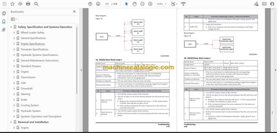
- Troubleshooting
- Removal and Installation
- Engine
- Safety Instructions
- Before Removing and Installing
- Engine and Transmission Assembly
- DEF (adblue®) Quality Sensor
- ECU (Engine Control Unit)
- Alternator
- Starter Motor
- Sensors – After Treatment
- V-Belt
- Hydraulic Systems and Structure
- Safety Instructions
- Before Removing and Installing
- Front Axle
- Rear Axle
- Drive Shaft
- Transmission Assembly
- Fuel Tank
- Joystick Valve (Work Lever)
- Cabin Assembly
- Undercovers
- Electric and Electronic
- Safety Instructions
- Before Removing and Installing
- Gauge Panel
- Battery Assembly
- Cabin Switches
- Cabin Photo Sensor
- DC-DC Controller
- Display Monitor
- EPOS Controller
- TCU Controller
- ACU Controller
- Microphone Controller
- Smart Key Controller
- TMS Controller
- Wiper Motor
- Combination Switch
- Transmission Lever
- Troubleshooting
- Wiring Harness Layout
- Safety Instructions
- Wiring Device
- Error Code
- Safety Instructions
- VCU Error Code
- ECU Error Code
- TCU Error Code
- Electric Steering Error Code
- Schematics
- DL380-7 / DL380-7- AH Hydraulic Schematic
- DL320-7 Electric Schematic
- Main Harness
Develon


