Format: PDF (Printable Document)
File Language: English
File Pages: 65
File Size: 918.83 KB (Speed Download Link)
File Count: 1 PDF file
Brand: Greer
Model: MicroGuard 510
Equipment Type: Load Moment Indicator
Book No: W450189B
Type of Document: Service Manual
Searchable: Yes, text is searchable and copyable
Delivery: Instant download after payment
$ 55
The Greer MicroGuard 510 is a load moment indicator. It monitors crane loading by reading boom angle, extension, pressure and radius, then alarms before the crane reaches its limits. When a sensor drifts or the display reads wrong, the crane sits idle. Fleet mechanics and shop technicians reach for this manual to calibrate the system in-house and get the unit back in service.
What this manual helps you do
Who this is for
A rental fleet mechanic or crane service technician who calibrates and maintains LMI systems in-house. It also suits an independent repair shop that takes in cranes with this system and has no documentation for it.
FAQ
Q: What do I receive and how is it organised?
A: You get 1 PDF file of 65 pages in English, with searchable text so you can jump straight to a command. It runs from pre-calibration requirements through the numbered commands to a glossary.
Q: Which equipment does it fit?
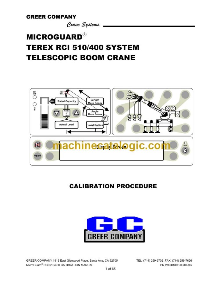
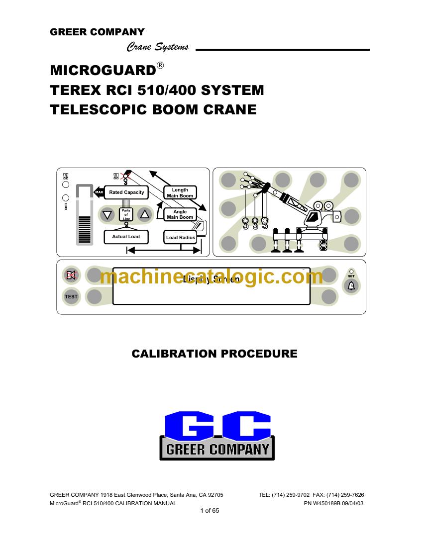
A: It is for the Greer MicroGuard 510 load moment indicator. The title on the manual reads MicroGuard RCI 510/400 Calibration Manual, publication number W450189B.
Q: How does it fit the job I'm doing?
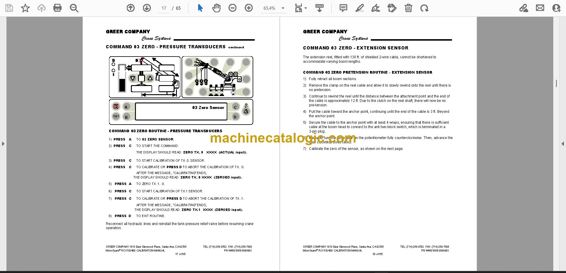
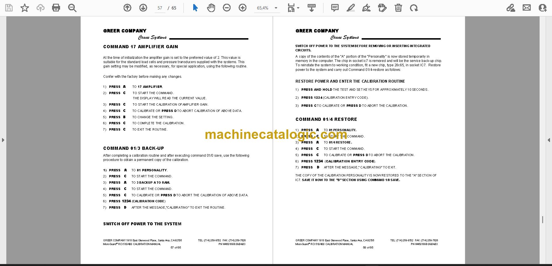
A: If you are calibrating sensors, setting alarm limits or tracing a fault on the unit, the command routines are laid out step by step. You can work through them at the crane with the display keys.
Keep it on your shop computer or tablet, and the next calibration on this LMI is documented and ready to go.
Click here to view the preview (PDF)