Format: PDF (Printable Document)
File Language: English
File Pages: 120
File Size: 7.01 MB (Speed Download Link)
Brand: Kohler
Model: 6EOD, 4.5EFOD, 8-32EOZD, 6.5-28EFOZD Marine
Book No: tp6255
Type of Document: Service Manual
$ 40
These Kohler marine gensets usually sit in tight, hot engine rooms, quietly carrying the electrical load for air conditioning, electronics, and hotel power while you’re underway or on the hook. This service manual is what I’d pull out when I need to trace a no-start, chase an intermittent shutdown, or verify adjustments after a repair. For example, if the unit cranks but won’t pick up and hold voltage, this book walks you through the checks so you can isolate whether you’ve got a fuel, speed-control, or generator-end issue before you start throwing parts at it.
Applications & Use Cases
FAQ
Q: Can I use this manual on a tablet or laptop in the engine room?
A: Yes, it works well digitally; you can zoom diagrams and search text, which speeds up fault tracing.
Q: Is it worth printing sections of this manual?
A: Many techs print the procedures they’re using that day so they can mark notes and keep it next to the set.
Safety Note
Always lock out power sources and allow hot components to cool before opening, testing, or adjusting these generators.
Safety Precautions and Instructions . . . . . . . . . . . . . . . . . . . . . . . . . . . . . . . . . . . . . . . . . . . . . . . . . . . . . . . . . 5
Introduction . . . . . . . . . . . . . . . . . . . . . . . . . . . . . . . . . . . . . . . . . . . . . . . . . . . . . . . . . . . . . . . . . . . . . . . . . . . . . . . 9
Service Assistance . . . . . . . . . . . . . . . . . . . . . . . . . . . . . . . . . . . . . . . . . . . . . . . . . . . . . . . . . . . . . . . . . . . . . . . . . 9
Section 1 Specifications . . . . . . . . . . . . . . . . . . . . . . . . . . . . . . . . . . . . . . . . . . . . . . . . . . . . . . . . . . . . . . . . . . . 11
1.1 General . . . . . . . . . . . . . . . . . . . . . . . . . . . . . . . . . . . . . . . . . . . . . . . . . . . . . . . . . . . . . . 11
1.2 Engine . . . . . . . . . . . . . . . . . . . . . . . . . . . . . . . . . . . . . . . . . . . . . . . . . . . . . . . . . . . . . . . 12
1.3 Generator, 4 Lead . . . . . . . . . . . . . . . . . . . . . . . . . . . . . . . . . . . . . . . . . . . . . . . . . . . . . 17
1.4 Generator, 12 Lead . . . . . . . . . . . . . . . . . . . . . . . . . . . . . . . . . . . . . . . . . . . . . . . . . . . . 18
1.5 Service Views . . . . . . . . . . . . . . . . . . . . . . . . . . . . . . . . . . . . . . . . . . . . . . . . . . . . . . . . . 19
1.6 Torque Specifications . . . . . . . . . . . . . . . . . . . . . . . . . . . . . . . . . . . . . . . . . . . . . . . . . . 20
Section 2 Scheduled Maintenance . . . . . . . . . . . . . . . . . . . . . . . . . . . . . . . . . . . . . . . . . . . . . . . . . . . . . . . . . . 27
2.1 General . . . . . . . . . . . . . . . . . . . . . . . . . . . . . . . . . . . . . . . . . . . . . . . . . . . . . . . . . . . . . . 27
2.2 Lubrication System . . . . . . . . . . . . . . . . . . . . . . . . . . . . . . . . . . . . . . . . . . . . . . . . . . . . 28
Section 3 Intake and Exhaust System . . . . . . . . . . . . . . . . . . . . . . . . . . . . . . . . . . . . . . . . . . . . . . . . . . . . . . . 29
3.1 Air Intake Silencer/Cleaner . . . . . . . . . . . . . . . . . . . . . . . . . . . . . . . . . . . . . . . . . . . . . . 29
3.2 Exhaust System Inspection . . . . . . . . . . . . . . . . . . . . . . . . . . . . . . . . . . . . . . . . . . . . . 30
3.3 Servicing Mixing Elbow . . . . . . . . . . . . . . . . . . . . . . . . . . . . . . . . . . . . . . . . . . . . . . . . . 31
3.4 Turbocharger (Models: 14/15/15.5/23/24EOZD and 11.5/13/20EFOZD) . . . . . . 31
Section 4 Fuel System . . . . . . . . . . . . . . . . . . . . . . . . . . . . . . . . . . . . . . . . . . . . . . . . . . . . . . . . . . . . . . . . . . . . . 33
4.1 General . . . . . . . . . . . . . . . . . . . . . . . . . . . . . . . . . . . . . . . . . . . . . . . . . . . . . . . . . . . . . . 33
4.2 Fuel Filter . . . . . . . . . . . . . . . . . . . . . . . . . . . . . . . . . . . . . . . . . . . . . . . . . . . . . . . . . . . . . 33
4.2.1 Priming the Fuel System . . . . . . . . . . . . . . . . . . . . . . . . . . . . . . . . . . . . . . . . 34
4.3 Fuel Pump (8–32EOZD and 6.5–28EFOZD Models) . . . . . . . . . . . . . . . . . . . . . . . . 36
4.4 Governor . . . . . . . . . . . . . . . . . . . . . . . . . . . . . . . . . . . . . . . . . . . . . . . . . . . . . . . . . . . . . 36
Section 5 Cooling System . . . . . . . . . . . . . . . . . . . . . . . . . . . . . . . . . . . . . . . . . . . . . . . . . . . . . . . . . . . . . . . . . . 37
5.1 General . . . . . . . . . . . . . . . . . . . . . . . . . . . . . . . . . . . . . . . . . . . . . . . . . . . . . . . . . . . . . . 37
5.2 Water-Cooled Exhaust Manifold . . . . . . . . . . . . . . . . . . . . . . . . . . . . . . . . . . . . . . . . . 38
5.3 Closed Heat Exchanger . . . . . . . . . . . . . . . . . . . . . . . . . . . . . . . . . . . . . . . . . . . . . . . . 38
5.4 Check and Fill Coolant . . . . . . . . . . . . . . . . . . . . . . . . . . . . . . . . . . . . . . . . . . . . . . . . . 38
5.5 Flush and Clean Cooling System . . . . . . . . . . . . . . . . . . . . . . . . . . . . . . . . . . . . . . . . 39
5.6 Pressure Cap . . . . . . . . . . . . . . . . . . . . . . . . . . . . . . . . . . . . . . . . . . . . . . . . . . . . . . . . . 39
5.7 Impeller Inspection and Replacement . . . . . . . . . . . . . . . . . . . . . . . . . . . . . . . . . . . . 39
5.8 Belt Tension . . . . . . . . . . . . . . . . . . . . . . . . . . . . . . . . . . . . . . . . . . . . . . . . . . . . . . . . . . . 40
5.8.1 Seawater Pump Belt Tensioning Procedure . . . . . . . . . . . . . . . . . . . . . . . 40
5.8.2 Battery Charging Alternator Belt Tensioning Procedure . . . . . . . . . . . . . 41
5.8.3 Anticorrosion Zinc Anode . . . . . . . . . . . . . . . . . . . . . . . . . . . . . . . . . . . . . . . 41
5.9 Siphon Break . . . . . . . . . . . . . . . . . . . . . . . . . . . . . . . . . . . . . . . . . . . . . . . . . . . . . . . . . 42
Section 6 Troubleshooting . . . . . . . . . . . . . . . . . . . . . . . . . . . . . . . . . . . . . . . . . . . . . . . . . . . . . . . . . . . . . . . . . 43
6.1 Introduction . . . . . . . . . . . . . . . . . . . . . . . . . . . . . . . . . . . . . . . . . . . . . . . . . . . . . . . . . . . 43
6.2 Initial Checks . . . . . . . . . . . . . . . . . . . . . . . . . . . . . . . . . . . . . . . . . . . . . . . . . . . . . . . . . . 43
6.3 General . . . . . . . . . . . . . . . . . . . . . . . . . . . . . . . . . . . . . . . . . . . . . . . . . . . . . . . . . . . . . . 43
6.4 Troubleshooting Chart . . . . . . . . . . . . . . . . . . . . . . . . . . . . . . . . . . . . . . . . . . . . . . . . . . 43
Section 7 Controller . . . . . . . . . . . . . . . . . . . . . . . . . . . . . . . . . . . . . . . . . . . . . . . . . . . . . . . . . . . . . . . . . . . . . . . 49
7.1 Introduction . . . . . . . . . . . . . . . . . . . . . . . . . . . . . . . . . . . . . . . . . . . . . . . . . . . . . . . . . . . 49
7.2 Advanced Digital Control Display and Keypad . . . . . . . . . . . . . . . . . . . . . . . . . . . . . 50
7.3 Sequence of Operation . . . . . . . . . . . . . . . . . . . . . . . . . . . . . . . . . . . . . . . . . . . . . . . . . 51
7.3.1 Starting Sequence, Master Switch Moved to RUN . . . . . . . . . . . . . . . . . . 51
7.3.2 Starting Sequence, Remote Start . . . . . . . . . . . . . . . . . . . . . . . . . . . . . . . . 51
7.3.3 Running Sequence . . . . . . . . . . . . . . . . . . . . . . . . . . . . . . . . . . . . . . . . . . . . 52
7.3.4 Stopping Sequence, Master Switch Moved to OFF/RESET . . . . . . . . . . 52
4 Table of Contents TP-6255 5/15
7.3.5 Stopping Sequence, Remote Stop . . . . . . . . . . . . . . . . . . . . . . . . . . . . . . . 52
7.4 Faults . . . . . . . . . . . . . . . . . . . . . . . . . . . . . . . . . . . . . . . . . . . . . . . . . . . . . . . . . . . . . . . . 52
7.4.1 Fault Shutdowns . . . . . . . . . . . . . . . . . . . . . . . . . . . . . . . . . . . . . . . . . . . . . . . 52
7.4.2 Warnings . . . . . . . . . . . . . . . . . . . . . . . . . . . . . . . . . . . . . . . . . . . . . . . . . . . . . 52
7.5 Controller Configuration and Adjustment . . . . . . . . . . . . . . . . . . . . . . . . . . . . . . . . . . 55
7.5.1 Controller Time Out . . . . . . . . . . . . . . . . . . . . . . . . . . . . . . . . . . . . . . . . . . . . 55
7.5.2 Controller Configuration . . . . . . . . . . . . . . . . . . . . . . . . . . . . . . . . . . . . . . . . 55
7.5.3 Voltage Adjustment . . . . . . . . . . . . . . . . . . . . . . . . . . . . . . . . . . . . . . . . . . . . 55
7.6 Controller Application Program . . . . . . . . . . . . . . . . . . . . . . . . . . . . . . . . . . . . . . . . . . 63
7.7 Silicon Controlled Rectifier (SCR) Module . . . . . . . . . . . . . . . . . . . . . . . . . . . . . . . . . 63
7.8 Continuous Power Mode Jumper, if equipped . . . . . . . . . . . . . . . . . . . . . . . . . . . . . . 65
7.9 Master Switch . . . . . . . . . . . . . . . . . . . . . . . . . . . . . . . . . . . . . . . . . . . . . . . . . . . . . . . . . 66
7.10 Relay Interface Board (RIB) . . . . . . . . . . . . . . . . . . . . . . . . . . . . . . . . . . . . . . . . . . . . . 67
7.11 Controller Replacement . . . . . . . . . . . . . . . . . . . . . . . . . . . . . . . . . . . . . . . . . . . . . . . . 68
Section 8 Component Testing and Adjustment . . . . . . . . . . . . . . . . . . . . . . . . . . . . . . . . . . . . . . . . . . . . . . . 71
8.1 Theory of Operation . . . . . . . . . . . . . . . . . . . . . . . . . . . . . . . . . . . . . . . . . . . . . . . . . . . . 71
8.2 Separate Excitation . . . . . . . . . . . . . . . . . . . . . . . . . . . . . . . . . . . . . . . . . . . . . . . . . . . . 71
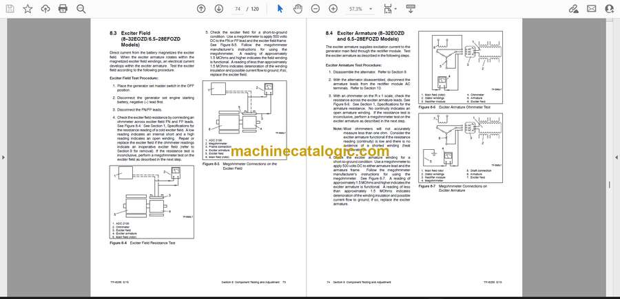
8.3 Exciter Field (8–32EOZD/6.5–28EFOZD Models) . . . . . . . . . . . . . . . . . . . . . . . . . . 73
8.4 Exciter Armature (8–32EOZD and 6.5–28EFOZD Models) . . . . . . . . . . . . . . . . . . 74
8.5 Slip Rings (6EOD/4.5EFOD Models) . . . . . . . . . . . . . . . . . . . . . . . . . . . . . . . . . . . . . 75
8.6 Brushes (6EOD/4.5EFOD Models) . . . . . . . . . . . . . . . . . . . . . . . . . . . . . . . . . . . . . . . 75
8.7 Rectifier Module (8–32EOZD and 6.5–28EFOZD Models) . . . . . . . . . . . . . . . . . . . 76
8.8 Rotor . . . . . . . . . . . . . . . . . . . . . . . . . . . . . . . . . . . . . . . . . . . . . . . . . . . . . . . . . . . . . . . . . 76
8.9 Stator . . . . . . . . . . . . . . . . . . . . . . . . . . . . . . . . . . . . . . . . . . . . . . . . . . . . . . . . . . . . . . . . 77
8.10 Voltage . . . . . . . . . . . . . . . . . . . . . . . . . . . . . . . . . . . . . . . . . . . . . . . . . . . . . . . . . . . . . . . 79
8.10.1 Voltage Regulation . . . . . . . . . . . . . . . . . . . . . . . . . . . . . . . . . . . . . . . . . . . . . 79
8.10.2 Voltage Adjustment . . . . . . . . . . . . . . . . . . . . . . . . . . . . . . . . . . . . . . . . . . . . 79
8.11 Four-Lead Reconnection . . . . . . . . . . . . . . . . . . . . . . . . . . . . . . . . . . . . . . . . . . . . . . . 81
8.11.1 100–120-Volt Configurations . . . . . . . . . . . . . . . . . . . . . . . . . . . . . . . . . . . . 81
8.11.2 100–120/200–240-Volt Configurations . . . . . . . . . . . . . . . . . . . . . . . . . . . . 81
8.11.3 200–240-Volt Configurations . . . . . . . . . . . . . . . . . . . . . . . . . . . . . . . . . . . . 82
8.12 Twelve-Lead Reconnection . . . . . . . . . . . . . . . . . . . . . . . . . . . . . . . . . . . . . . . . . . . . . 82
8.13 Fault Shutdown Tests . . . . . . . . . . . . . . . . . . . . . . . . . . . . . . . . . . . . . . . . . . . . . . . . . . 83
8.13.1 Controller Fault Shutdown Functions . . . . . . . . . . . . . . . . . . . . . . . . . . . . . 83
8.13.2 Fault Shutdown Switches . . . . . . . . . . . . . . . . . . . . . . . . . . . . . . . . . . . . . . . 84
8.14 Fuses . . . . . . . . . . . . . . . . . . . . . . . . . . . . . . . . . . . . . . . . . . . . . . . . . . . . . . . . . . . . . . . . 85
8.15 Continuity Checks . . . . . . . . . . . . . . . . . . . . . . . . . . . . . . . . . . . . . . . . . . . . . . . . . . . . . 85
Section 9 Generator Disassembly/Reassembly . . . . . . . . . . . . . . . . . . . . . . . . . . . . . . . . . . . . . . . . . . . . . . 87
9.1 Disassembly . . . . . . . . . . . . . . . . . . . . . . . . . . . . . . . . . . . . . . . . . . . . . . . . . . . . . . . . . . 87
9.2 Collector Ring and Bearing Replacement (6EOD/4.5EFOD Model) . . . . . . . . . . . 91
9.3 Reassembly . . . . . . . . . . . . . . . . . . . . . . . . . . . . . . . . . . . . . . . . . . . . . . . . . . . . . . . . . . 91
Section 10 Wiring Diagrams . . . . . . . . . . . . . . . . . . . . . . . . . . . . . . . . . . . . . . . . . . . . . . . . . . . . . . . . . . . . . . . . 95
10.1 Wiring Diagram Reference . . . . . . . . . . . . . . . . . . . . . . . . . . . . . . . . . . . . . . . . . . . . . . 95
10.2 Manual Marine (Ship-to-Shore) 2 Wire and 3 Wire Transfer Switches . . . . . . . . . 108
10.3 Manual Marine (Ship-to-Shore) 4 Wire Transfer Switch . . . . . . . . . . . . . . . . . . . . . 109
Appendix A Abbreviations . . . . . . . . . . . . . . . . . . . . . . . . . . . . . . . . . . . . . . . . . . . . . . . . . . . . . . . . . . . . . . . . . . . 111
Appendix B Common Hardware Application Guidelines . . . . . . . . . . . . . . . . . . . . . . . . . . . . . . . . . . . . . . . . . 113
Appendix C General Torque Specifications . . . . . . . . . . . . . . . . . . . . . . . . . . . . . . . . . . . . . . . . . . . . . . . . . . . . 114
Appendix D Common Hardware Identification . . . . . . . . . . . . . . . . . . . . . . . . . . . . . . . . . . . . . . . . . . . . . . . . . . 115
Appendix E Common Hardware List . . . . . . . . . . . . . . . . . . . . . . . . . . . . . . . . . . . . . . . . . . . . . . . . . . . . . . . . . . 116


