Kohler KD36V16, KD45V20 Diesel Engine Service and Repair Manual (33525088301)
These KD-series Kohler diesels usually live in tough spots—generators, compact equipment, pumps—running long hours in dusty, hot, or damp environments. This manual is what I’d keep open on the bench when I’m stripping one down, so I can verify clearances, tightening patterns, and test points instead of guessing. If, for example, the engine starts hunting under load or is hard to restart warm, I’d use this book to trace the fuel system step by step, inspect the governor linkage correctly, and then reassemble everything in the right order.
Applications & Use Cases
- Planning a repair workflow before tearing down the KD36V16 or KD45V20 so no parts or checks are missed.
- Guiding disassembly and reassembly, with proper sequences to avoid warping housings or misaligning rotating parts.
- Tracing hard-start, smoke, or power-loss issues by methodically checking fuel, air, and control components.
- Inspecting wear items—seals, bearings, injectors—so you replace what’s needed while it’s open.
- Verifying adjustments after repairs, like linkage travel or component alignment, to prevent repeat failures.
FAQ
Q: Can I keep this manual on a tablet in the workshop?
A: Yes, it’s practical to use digitally so you can zoom in on diagrams and search quickly while you work.
Q: Is it worth printing certain sections?
A: Many techs print the pages for the job they’re doing, then tape them near the engine to avoid handling devices with dirty hands.
Safety Note
Always follow the manual’s safety instructions and lockout procedures before working on or near a running engine.
📘 Show Index
Kohler KD36V16, KD45V20 Diesel Engine Index:
- Revision history
- 1 Safety
- 1.1 Safety instructions
- 1.2 Target audience
- 1.2.1 International standard classification of occupations
- 1.2.2 Occupational references
- For the Service Level 1 maintenance of power generation engines: Maintenance Technician
- For the Service Level 2 maintenance of power generation engines: Technician
- For the Service Level 3 maintenance of power generation engines: Mechanical Technician
- 1.2.3 Unauthorized personnel
- For the operation of power generation engines: Operator
- 1.3 Intended use
- 1.4 Unauthorized Use
- 1.5 General safety instructions
- 1.6 Preventing personal injuries
- 1.6.1 Bruises
- 1.6.2 Risk of burns
- 1.6.3 Fires and explosions
- 1.6.4 Poisoning
- 1.6.5 Electrical energy
- 1.6.6 Danger due to noise
- 1.7 Personal protective equipment
- 1.8 Operating and maintenance areas
- Safety instructions
- Operating areas
- Maintenance areas
- 1.8.1 Secure the Diesel engine against unexpected starting and recommission
- 1.8.2 Emergency stop
- 1.8.3 Signage
- 1.9 Preventing material damages
- 2 General information
- 2.1 Layout of these instructions
- 2.2 Engine illustrations and engine parts
- View of power unit support side
- View of flywheel side
- Gear train
- 2.3 Signage
- 2.3.1 Safety signs
- Raise the Diesel engine hang tag
- 2.3.2 Notice signs
- Hang tag engine without engine oil
- 2.3.3 General engine data
- Engine type designation KD36V16
- Engine type designation KD45V20
- Emission control information label
- Engine serial number
- Cylinder designation engine KD36V16
- Cylinder designation engine KD45V20
- Con rod number (split con rod)
- Exhaust gas turbocharger nameplate
- Engine control unit nameplates
- Thermostat start of opening
- 2.4 Fuel scheme (engine KD36V16)
- 2.5 Fuel scheme (engine KD45V20)
- 2.6 Lubricant scheme
- 2.7 Coolant scheme
- 2.8 Engine electrics
- 2.8.1 Overview of sensors and actuators (engine KD36V16)
- 2.8.2 Overview of sensors and actuators (engine KD45V20)
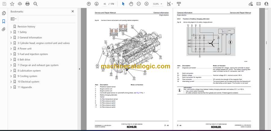
- 2.8.3 Function of battery charging alternator
- Excitation for battery charging alternator
- 2.8.4 Starter function
- Starting the Diesel engine
- 2.8.5 Breakdown of cable names acc. to wiring diagram
- 2.9 Arrangement of channels in the crankcase and cylinder head
- 2.10 Transport stand and fastening pieces
- 2.11 Lifting device and fastening pieces
- 2.11.1 Fitting and removing fastening pieces
- Tightening instructions for lifting device
- 2.12 Transporting the Diesel engine
- 2.12.1 Fastening during transport
- 2.12.2 Steel transport stand
- 2.12.3 Wooden transport stand
- 2.13 Starting the engine
- 3 Cylinder head, engine control unit and valves
- 3.1 Fitting and removing the cylinder head cover
- Tightening instructions for wiring harness at injector
- 3.1.1 Fitting the seal for the cylinder head cover
- 3.2 Checking and setting the valve clearance (engine KD36V16)
- Setting position “TDC”
- Setting position “TDC +180°”
- Setting position “TDC +360°”
- Setting position “TDC +450°”
- 3.3 Checking and setting the valve clearance (engine KD45V20)
- Setting position “TDC”
- Setting position “TDC +180°”
- Setting position “TDC +360°”
- Setting position “TDC +450°”
- 4 Power unit
- 4.1 Fitting and removing the crankshaft add-on parts
- Tightening instructions for the crankshaft add-on parts
- 5 Fuel and injection system
- 5.1 Safety instructions for work on the fuel and injection system
- 5.1.1 Preventing personal injuries
- 5.1.2 Preventing material damages
- 5.2 Fitting and removing fuel lines
- 5.2.1 Low pressure fuel lines (engine KD36V16)
- 5.2.2 Low pressure fuel lines (engine KD45V20)
- 5.2.3 Fuel lines – return and permanent ventilation (engine KD36V16)
- 5.2.4 Fuel lines – return and permanent ventilation (engine KD45V20)
- 5.3 Fitting and removing the injection line (engine KD36V16)
- Tightening instructions for injection lines
- Injection lines – box nut, width A/F 17
- Injection lines – box nut, width A/F 19
- Pipe clip – hex screw M6x16 8.8
- Pipe clip – hex screw M8x16 8.8
- 5.3.1 Removing
- 5.3.2 Fitting
- 5.4 Fitting and removing the injection line (engine KD45V20)
- Tightening instructions for injection lines
- Injection lines – box nut, width A/F 19
- Sealing plugs – box nut, width A/F 19
- Hex screws M8x16 8.8
- 5.4.1 Removing
- 5.4.2 Fitting
- 5.5 Fitting and removing the rail
- Procedure for fitting the rail
- Hex screw M8x40 8.8
- 5.6 Fitting and removing the pressure adapter and injector
- 5.6.1 Removing
- 5.6.2 Fitting
- Tightening instructions for injector and pressure adapter
- 5.7 Fitting and removing the high pressure pumps (engine KD36V16)
- Tightening instructions for the HP pump
- 5.7.1 Removing the HP pumps
- 5.7.2 Fitting the HP pumps
- 5.7.3 Setting the HP pumps
- 5.8 Fitting and removing the HP pump drive (engine KD36V16)
- 5.8.1 Sealant curve HP pump drive
- 5.9 Fitting and removing the HP pump drive (engine KD45V20)
- Assembly instructions HP pump drive
- 5.9.1 Removing the HP pump with HP pump drive
- 5.9.2 Fitting the HP pump drive with HP pump
- 6 Belt drive
- 6.1 Fitting and removing the belt
- 6.1.1 Fitting and removing the fan drive belt
- 6.1.2 Belt tensioning device with automatic belt tensioning
- 7 Charge air and exhaust gas system
- 7.1 Fitting and removing the intake stack before the compressor
- 7.2 Fitting and removing the charge air line
- 7.3 Fitting and removing the charge air control unit (engine KD36V16)
- 7.4 Fitting and removing the charge air control unit (engine KD45V20, only 1800 rpm)
- 7.5 Fitting and removing the air intake pipe
- 7.6 Fitting and removing the exhaust gas stub
- 7.7 Fitting and removing the exhaust gas turbocharger (engine KD36V16)
- Tightening instructions turbocharger and flange on turbocharger
- 7.8 Fitting and removing the exhaust gas turbocharger (engine KD45V20)
- Tightening instructions turbocharger and flange on turbocharger
- 8 Lubrication system
- 8.1 Fitting and removing the crankcase breather piping (engine KD36V16)
- 8.2 Fitting and removing the crankcase breather piping (engine KD45V20)
- 9 Cooling system
- 9.1 Emptying the coolant system
- 9.2 Fitting and removing the vent line
- 9.3 Fitting and removing the thermostat housing
- 9.4 Fitting and removing the coolant pump
- 9.5 Thermostat
- 10 Electrical system
- 10.1 Fitting and removing the battery charging alternator
- Tightening instructions for battery charging alternator
- 10.2 Fitting and removing the starter
- Tightening instructions starter
- 10.3 Fitting and removing the engine control unit including add-on
- 10.3.1 Removal instructions engine control unit
- 10.3.2 Installation instructions engine control unit
- Tightening instructions engine control unit add-on
- 11 Appendix
- 11.1 Standard torques
- 11.1.1 Standard torques for screw connections
- 11.1.2 Standard torques for screw plugs and hollow screws
- 11.1.3 Standard torques for flange joints
- Metric flange joints, series L (light) acc. to Fig. 150
- Metric flange joints, series S (heavy) acc. to Fig. 150
- Imperial flange joints, series L (light) acc. to Fig. 150
- Imperial flange joints, series S (heavy) acc. to Fig. 150
- Metric flange joints, series L (light) for aluminum acc. to Fig. 150
- 11.1.4 Standard torques for cutting ring flange joints
- 11.1.5 Standard torques for Triple Lock flange joints
- 11.1.6 Standard torques for VSTI screw plugs
- 11.2 Detergents, threadlocks and greases
- 11.3 Tools
- 11.3.1 Special tools
- 11.3.2 Special tools with order number
- 11.4 Terms used (glossary)
- 11.5 Abbreviations used
Kohler


