Format: PDF (Printable Document)
File Language: English
File Pages: 170
File Size: 23.54 MB (Speed Download Link)
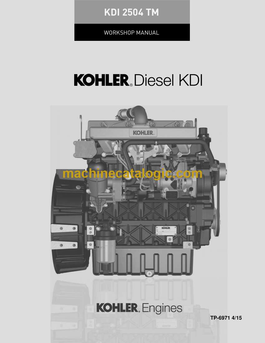
Brand: Kohler
Model: KDI 2504 TM Diesel
Book No: tp6971
Type of Document: Workshop Manual
$ 40
These KDI 2504 TM diesels usually work hard in compact equipment, generators, and industrial machines that sit in dust, mud, and vibration all day. This workshop manual is what I’d pull out when I’m tearing one down on the bench and need to rebuild it once, correctly, then get it back in the frame without surprises. If you’re chasing a hard-start complaint after an overheating incident, for example, this book walks you through a logical strip-down, inspection, and reassembly so you can trace damage, verify clearances, and avoid repeat failures.
Applications & Use Cases
FAQ
Q: Can I keep this manual open on a tablet in the shop?
A: Yes, it’s convenient to use digitally so you can zoom diagrams and search quickly while you’re at the bench.
Q: Is it worth printing sections of this manual?
A: Many techs print only the procedures they’re doing that day, so they can mark notes, tape them to the machine, and avoid getting a tablet filthy.
Safety Note
Always follow the manual’s lockout, lifting, and support instructions before removing or refitting any major engine components.
GENERAL INFORMATION
Useful information
Useful Information -accident prevention – environmental impact
Manufacturer and engine identification
Identification of the man internal of the engine and operating reference (BASE CONFIGURATION)
Identification of the extemal components of the engine (BASE CONFIGURATION)
TECHNICAL INFORMATION
Engine specifications
Engine dimensions (mm)
Performance diagrams
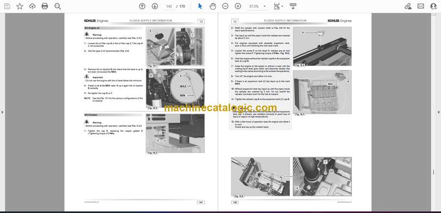
Oil
SAE oil classification
International lubricant specifications
Fuel
Fuel for low temperatures
Biodiesel fuel
Emission-Related Installation Instructions
Coolant
Battery features
Periodic maintenance
Fuel system
Supply system
Fuel return circuit
Injection pump
Injector
Fuel filter
Electric fuel pump (optional)
Guards for fuel injection circuit components
Lubrication circuit
Lubrication circuit diagram
Oil pump
Oil filter and Oil Cooler
Coolant circuit
Coolant circuit diagram
Coolant pump
Thermostatic valve
Radiator (optional)
Intake and exhaust circuit
Air filter (optional)
Turbocharger
Electric system
Engine electrical wiring (opzional)
Connector panel on the engine/machine
Accessories panel connector
Wiring disconnection
Sensors and switches
Fuel filter water detection sensor
Oil pressure switch
Coolant temperature sensor
Air cleaner clogging switch
Electrical components
Alternator
Starter motor
Cold starting device (Heater)
Electric fuel pump (optional)
Cold Start Advance
Electro-Stop
Control panel (optional)
Timing system and tappets
Components identification
Tming system phasing angles
Rocker am pin
Rocker arms
Hydraulic tappets
Hydraulic tappet operation
Difficult operating conditiorz
Balancer device
Components handling
Injection punp
Injector
Turbocharger
Turbocharger
What to do md what not to do
Practical operating rules
Before installing a new turbocharger
Installation instructions
Replacement instructions
SAFETY INFORMATION
Before start-up
Safety precautions
General remaNs
Note for OEM
Nde for end user
SAFETY SIGNAL DESCRIPTION
Adhesive safety plates
Warnings
Safety guards
Information and safety signals
Safety and environmental impact
Location of safety signals on engine
STORAGE INFORMATION
Product preservaton
Engine storage (LD to 6 months)
Engine storage (over 6 rmnths)
Engine starting after storage
Coolant
Engine oil
INFORMATION FOR REPLACING THE FUNCTIONAL UNITS
Injector and injection pump replacement
Injection fuel pipes disassembly(iriection pump”rjectors)
Rocker arms ccwer disassembly
Fuel retum pipes disasserrbty
Injectors disassembl•y
Injection p•L.mp disassenlbly
Injection pump assembly
Injector assembly
Assembly of the injector retum pipes
Assembty Rocker arm cover
Installation of the fuel injector pipes (vnp injector,nectors)
Coolant purrp replacement
Disassembly
Replace the crankshaft pulley
Assembly
Oil pump replacen•ent
Coolant pump disassembly
Engine pulley disassembly
Timing system crankcase disassembly
Oil pump disassembly
Oil pump assembly
Timing system crankcase assembly
Crankshaft puley assembty
Coolant pump assembly
Oil pressure replacement
Disassembly
Assembly
Oil cooler unit and oil filter replacernent
Oil Cooler unit disassembly
Oil filter cartridge replacement
Oil Cooler unit assembly
Fuel filter replacenznt
Disassembly
Assembly
Oil vapour separator replacement
Disassembly
Assembly
DISASSEMBLY INFORMATION
Recommendations for disassembly
Electric components disassembly
Electric wiring
Starter motor
Belt and alternator
Sensors and switches
1 Oil pressure switch disassembty
2 Coolant temperature sensor
3 Fuel filter water detection sensor
Turbocharger disassembly
Exhaust manifold disassembly
Coolant recirculation components disassembty
Oil Cooler manifold
Thermostatic valve
Coolant pump
Crankshaft pulley disassembty
Lubrication circuit disassembly
Oil pressure ‘Äve
Timing system carter oil filing flange
Tlming system
Oil pump
Oil Cooler unit and lub. oil filter
Oil cooler unit
I make manifold disassembly
Fuel system disassembty
Fuel injection pipes
Rocker arm cover
Fuel retum pipes
Irjector
l*ction pump
Fuel filter
Tlming system gear disassembly
Flange unit disassembly
Flywheel
Flange housing
Cylinder head unit disassembly
Rocker arm pin
.1 Rocker arm
Varve rods and bridges
Cylinder head
INFORMATION ABOUT OVERHAULING
Recommendations for overhauls and tuning
Crankcase
Oil line check
Cylinder check
Camshaft housing check
Camshaft control
Tappets and tappet housings
Tappets check
Tappet housing check
Crankshaft
Dimensional check and overhauling
Checking the axial clearance of the crankshaft
Connecting rod – piston assembly
Connecting rod dimensions check
Checking the gudgeon pin-pin axes are parallel
Piston rings check
Piston dimension check
Cylinder head
Flatness check
Valve seats check
Valve springs
Valve guides check
Valve guides replacement
Valve guides replacement
Oil pump check
Dimensional and visual check
Rotors clearance check
Oil pressure valve check
ASSEMBLY INFORMATION
Information on engine configuration
Assembly recommendations
Engine block assembly
Semi main bearings
Tappets
Camshaft
Oil spray nozzles
Crankshaft
Lower crankcase
Piston rings
Piston
Piston and connecting rod assembly
Crankshaft gasket flange
Cover 3rd PTO
Oil sump unit assembly
Oil vapour pipe
Oil suction pipe
Oil Sump
Flange unit assembly
Bell housing
Flywheel
Timing system gear assembly and injection pump
Timing system gear assembly
Injection pump
Cylinder head unit assembly
Valve stem gasket
Injector sleeves
Injectors projection
Valves
Cylinder head
Rods and valve bridges
Rocker arms
Rocker arm pin assembly
Fuel system assembly
Injector
Fuel injector ricicle pipe
Rocker arm cover
Installation of the fuel injector pipes (injection pumphnjectors)
Fuel filter
Intake manifold assembly
Exhaust manifold assembly
Lubrication circuit assembly
Assembly oil mist separator unit
Oil Cooler and oil filter Unit Assembly
Oil pump
Timing system crankcase
Crankcase oil filler flange Timing System
Oil pressure relief valve
Crankshaft pulley assembly
Turbocharger Assembly
Coolant circuit assembly
Thermostatic valve
Coolant pump
Oil Cooler hoses
Electric component assembly
Sensors and switches
.1 Water temperature sensor
.2 Oil Pressure Switch
.3 Fuel filter water detection sensor
Altemator
Starter Motor
Summary table of tightening torques and the use of sealants


