Format: PDF (Printable Document)
File Language: English
File Pages: 221
File Size: 13.74 MB (Speed Download Link)
Brand: Komatsu
Model: D375A-6R Bulldozer
Book No: GEN00098-10
Serial No: 65001 and up
Type of Document: Field Assembly Manual
$ 39
Cover
Preface
CONTENTS
Specifications
Precautions for field assembly
Disposal of removed parts
Assembly procedure, necessary equipment, and schedule
Layout of kit
Style for transportation
Table of tools for field assembly
Tightening torque
Coating materials list
Selection of wire ropes used for assembly
A. Assembly
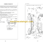
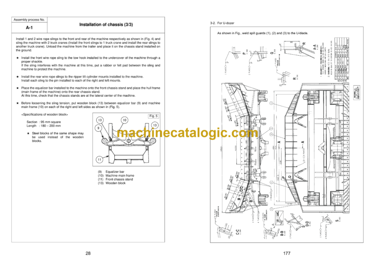
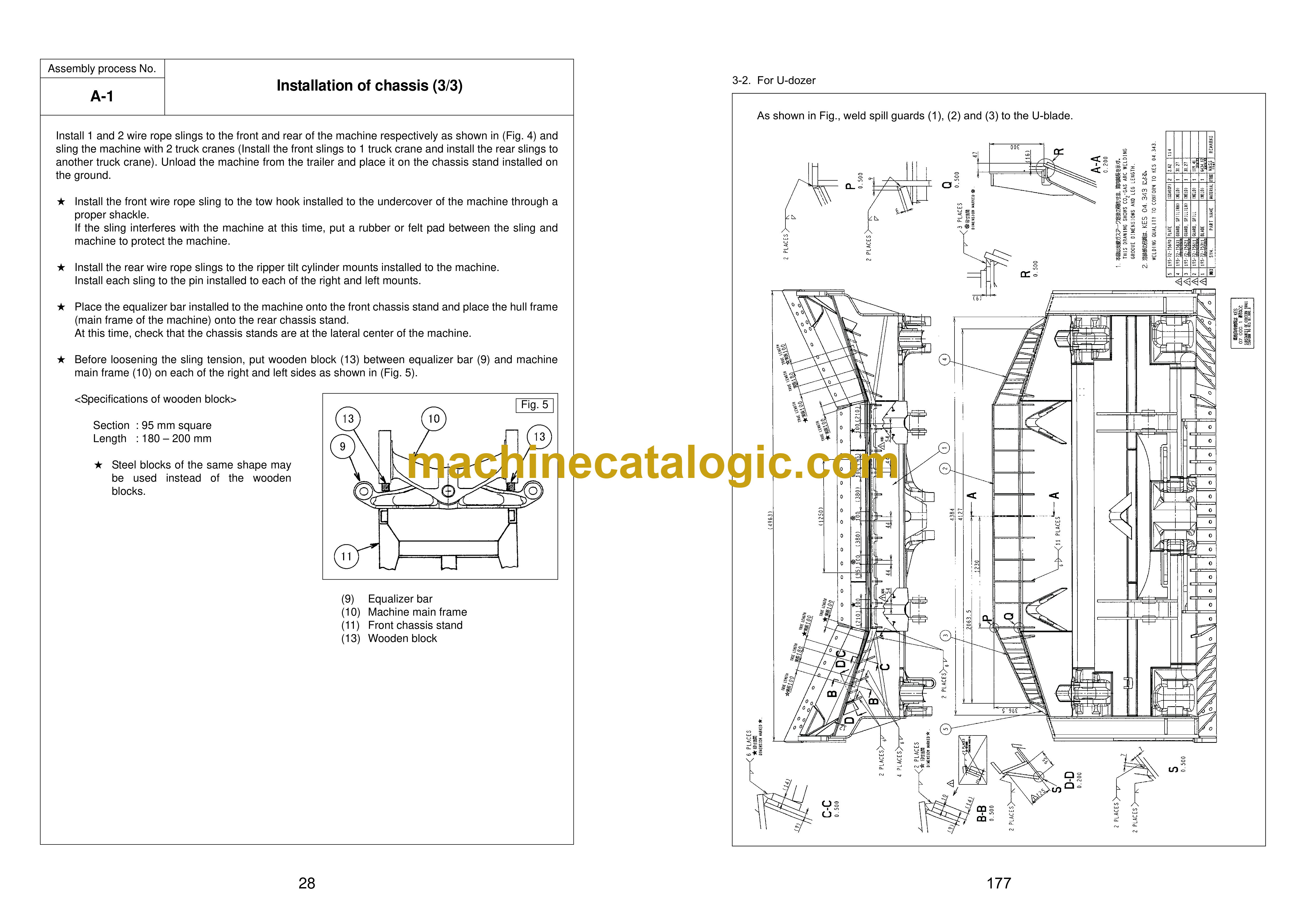
A-1 Installation of chassis
A-2 Installation of undercover
A-3 Installation of pivot shaft
A-4 Installation of undercarriage
A-5 Adding oil to recoil chamber and pivot chamber
A-6.1 Installation of engine air inlet hood
A-6.2 Installation of engine air pre-cleaner (if equipped)
A-7 Installing direction of exhaust pipe
A-8 Installation of blade lift cylinder
A-9 Installation of ripper
A-10 Installation of track
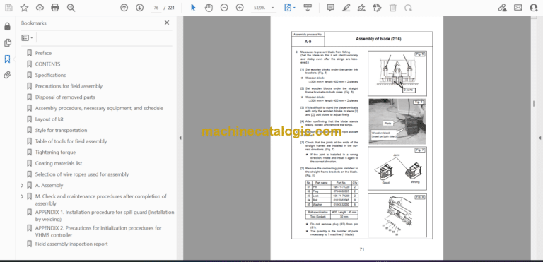
A-11 Assembly of blade
A-12 Installation of blade
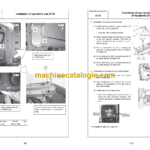
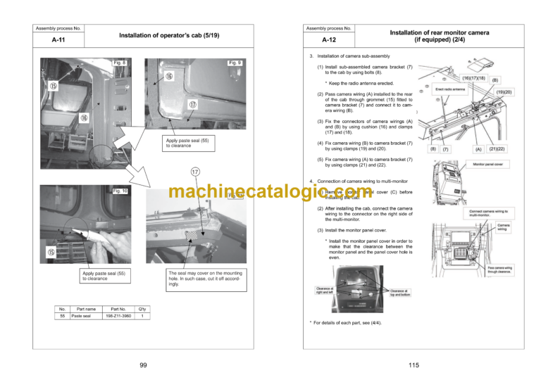
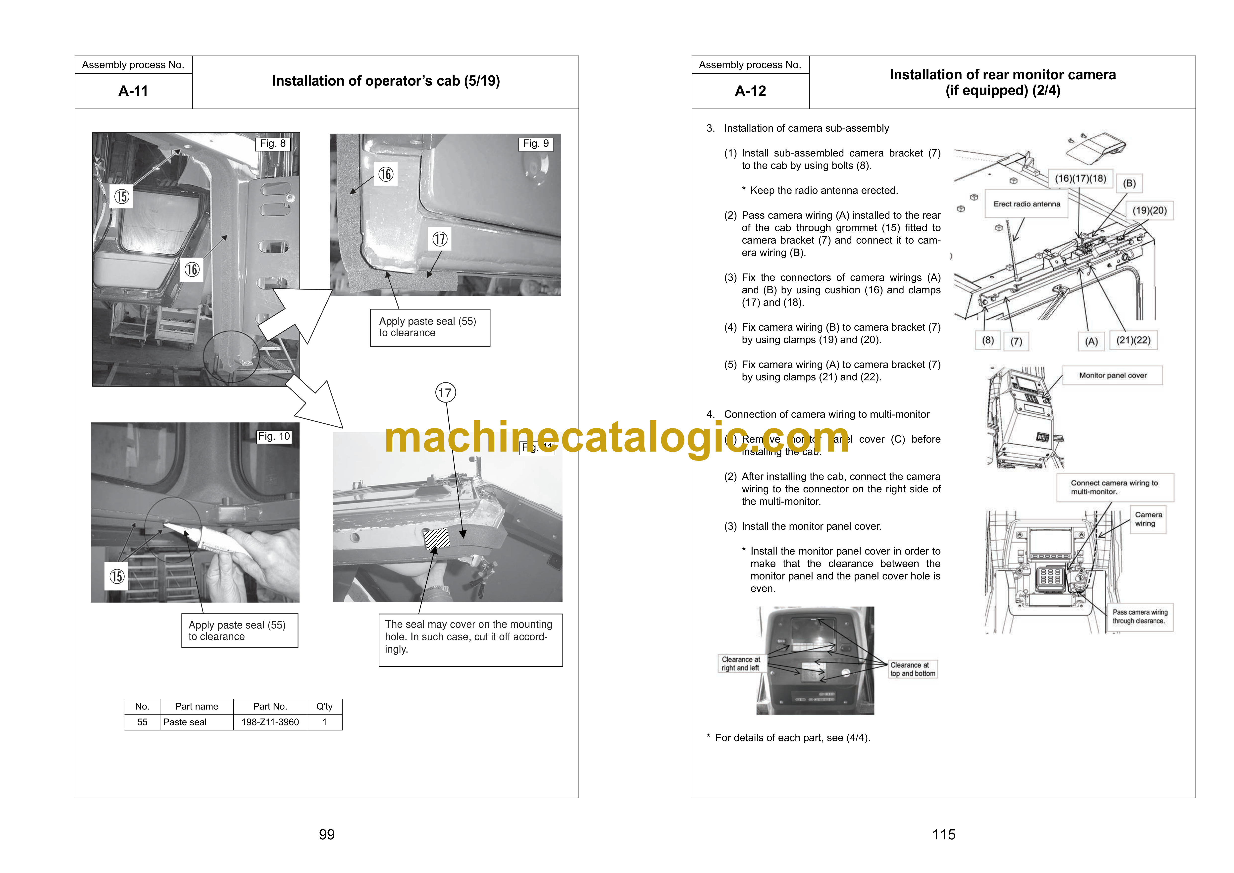
A-13 Installation of operator’s cab
A-14 Installation of rear monitor camera (if equipped)
A-15 Installation of additional cab lights (if equipped)
A-16 Installation of ROPS
A-17 Installation of VHMS, ORBCOMM antenna
A-18 Installation of revolving warning lamp to top of ROPS (if equipped)
A-19 Check track tension
A-20 Check fuel, coolant and lubricants
A-21 Bleeding air from hydraulic cylinders
A-22 Lubricating
A-23 Installation of fuel quick charge piping (if equipped)
M. Check and maintenance procedures after completion of assembly
M-1 Check and adjustment of operator’s cab
M-2 Inspection of machine monitor
M-3 Checking operation of dual tilt mechanism (If equipped)
M-4 Setting procedure for USER ADJUST MODE
M-5 Setting procedure for maximum cooling fan speed
M-6 Replacement of return filter (Replacement of standard filter -> special flushing parts)
M-7 Flushing of hydraulic circuit, and bleeding air from hydraulic cylinders (Part 1)
M-8 Replacement of return filter (Replacement of special flushing parts -> standard filter)
M-9 Bleeding air from hydraulic cylinders (Part 2)
APPENDIX 1. Installation procedure for spill guard (Installation by welding)
APPENDIX 2. Precautions for initialization procedures for VHMS controller
Field assembly inspection report
