These Komatsu HB335-1, HB335LC-1, HB365-1 crawler excavators are hybrid machines used for heavy digging, loading, and production work where fuel savings matter. The Komatsu HB335-1, HB335LC-1, HB365-1 Crawler Excavator Shop Manual (SEN06366-08) is what technicians and serious fleet shops reach for when a fault code won’t clear, a component has to come off the machine, or a system needs proper setup after repair. People buying this type of manual are usually trying to do accurate diagnosis, safe disassembly/reassembly, and bring the machine back to spec, not just basic checks.
What this manual helps you do
- Trace hydraulic and hybrid system faults using step‑by‑step diagnostic flows and wiring/hydraulic diagrams you’d expect in a shop manual.
- Check engine, electric motor, and generator system issues with the kind of test procedures most shops use during real troubleshooting.
- Follow correct disassembly and reassembly sequences for major components like swing machinery, final drives, boom/stick, and cylinders.
- Diagnose electronic control problems by following signal checks at connectors and using the expected error code references.
- Handle post‑repair setup and calibration so sensors, hybrid components, and controls talk to each other the way the factory intended.
Who this is for
This manual is aimed at field techs, shop mechanics, and advanced trainees who are actually turning wrenches on these specific hybrid excavators. If you just want to learn basic operation or daily inspections, you’d be better off with the Operation & Maintenance Manual instead.
FAQ
Q: Is this a PDF I can search and print?
A: Yes, this kind of shop manual is typically provided as a searchable PDF that you can view on a laptop or print selected pages for the shop.
Q: Is it deep enough for full rebuilds or just light service?
A: The Shop Manual for Komatsu HB335-1, HB335LC-1, HB365-1 Crawler Excavator walks through diagnostic procedures, disassembly sequences, and reference torque tables used during workshop-level repairs.
Q: How do I know it matches my exact machine variant?
A: You’ll want to match your machine’s model designation and serial details to book reference SEN06366-08; if they don’t line up, you should look for the correct Komatsu shop manual issue.
Bottom line: if you’re repairing or diagnosing HB335-1, HB335LC-1, or HB365-1 machines in a workshop or field setting, this is the right manual; if you’re just operating them, keep looking for the operator or O&M book instead.
📘 Show Index
Table of Contents:
- 00 Index and foreword
- Index
- Foreword, safety and general information
- Important safety notice (Hybrid)
- How to read the shop manual
- Explanation of terms for maintenance standard
- Handling equipment of fuel system devices
- Handling of intake system parts
- Handling of hydraulic equipment
- Method of disconnecting and connecting of push-pull type coupler
- Handling of electrical equipment
- How to read electric wire code (Hybrid)
- Precautions when performing operation
- Practical use of KOMTRAX
- Handling hybrid components and high voltage wiring harness
- Standard tightening torque table
- List of abbreviation
- Conversion table
- 01 Specification
- Table of contents
- Specifications
- Specification drawing
- Working range drawings
- Specifications
- Weight table
- Table of fuel, coolant, and lubricants
- 10 Structure and function
- Table of contents
- Engine and cooling system
- Engine related parts
- VGT
- EGR system piping drawing
- EGR system circuit diagram
- EGR valve
- EGR cooler
- Cooling system
- Hybrid system
- Outline of hybrid system
- Configuration of hybrid system
- Protective function of hybrid component
- Protection function for workers when disassembling hybrid component
- Cooling system of hybrid component
- Interlock function
- Motor-generator
- Electric swing motor
- Electric control unit
- High voltage wiring harness (power cable)
- Water pump
- Power train
- Power train system
- Swing circle
- Swing machinery with swing brake
- Final drive
- Undercarriage and frame
- Track frame and idler cushion
- Hydraulic system
- Hydraulic component layout
- Valve control
- Hydraulic tank
- CLSS
- Main pump
- Control valve
- Travel motor
- PPC valve
- Solenoid valve
- Attachment circuit selector valve
- Center swivel joint
- Accumulator
- Work equipment
- Electrical system
- Electrical control system
- System component parts
- Machine monitor system
- KOMTRAX system (GPRS type)
- KOMTRAX system (Orbcomm type)
- Sensor
- 20 Standard value tables
- Table of contents
- Standard service value table
- Standard value table for engine
- Standard value table for machine
- 30 Testing and adjusting
- Table of contents
- Related information on testing and adjusting
- Tools for testing and adjusting
- Sketch of tools for testing and adjusting
- Engine and cooling system
- Testing engine speed
- Testing boost pressure
- Testing exhaust gas color
- Testing and adjusting valve clearance
- Testing compression pressure
- Testing blowby pressure
- Testing engine oil pressure
- Testing EGR valve and VGT oil pressures
- Testing fuel pressure
- Testing fuel discharge, return and leakage
- Bleeding air from fuel system
- Testing fuel circuit for leakage
- Handling cylinder cutout mode operation
- Handling no-injection cranking operation
- Checking and adjusting air conditioner compressor belt tension
- Replacing fan belt
- Replacing alternator belt
- Hybrid system
- Precautions related to hybrid equipment
- Bleeding air from hybrid cooling system
- Testing water pressure of hybrid coolant
- Testing swing parking brake
- Cleaning and replacing oil filter of electric swing motor
- Testing operation of swing emergency stop switch
- Power train
- Testing swing circle bearing clearance
- Undercarriage and frame
- Testing and adjusting track tension
- Hydraulic system
- Releasing remaining pressure from hydraulic circuit
- Testing oil pressure of control circuit
- Testing and adjusting oil pressure in work equipment and travel circuits
- Testing and adjusting oil pressure in pump PC control circuit
- Testing and adjusting oil pressure in pump LS control circuit
- Testing outlet pressure of solenoid valve
- Testing PPC valve outlet pressure
- Adjusting play of work equipment and swing PPC valves
- Testing pump swash plate sensor
- Isolating the parts causing hydraulic drift in work equipment
- Testing oil leakage
- Bleeding air from hydraulic circuit
- Cab and its attachments
- Checking cab tipping stopper
- Adjusting mirrors
- Electrical system
- Special functions of machine monitor
- KOMTRAX terminal start-up procedure
- Adjusting rearview camera angle
- Handling voltage circuit of engine controller
- Testing diodes
- Pm clinic
- 40 Troubleshooting
- Table of contents
- Related information on troubleshooting
- Troubleshooting points
- Sequence of events in troubleshooting
- Checks before troubleshooting
- Inspection procedure before troubleshooting
- Preparation work for troubleshooting of electrical system
- Classification and procedures for troubleshooting
- Symptom and troubleshooting numbers
- Information in troubleshooting table
- Troubleshooting method for open circuit in wiring harness of pressure sensor system
- Connector list and layout
- Connector contact identification
- T-branch box and T-branch adapter table
- Fuse location table
- Failure codes table
- Troubleshooting by failure code (Display of code)
- Failure code [879AKA] A/C Inner Sensor Open Circuit
- Failure code [879AKB] A/C Inner Sensor Short Circuit
- Failure code [879BKA] A/C Outer Sensor Open Circuit
- Failure code [879BKB] A/C Outer Sensor Short Circuit
- Failure code [879CKA] Ventilating Sensor Open Circuit
- Failure code [879CKB] Ventilating Sensor Short Circuit
- Failure code [879DKZ] Sunlight Sensor Open Or Short Circuit
- Failure code [879EMC] Ventilation Damper Abnormality
- Failure code [879FMC] Air Mix Damper Abnormality
- Failure code [879GKX] Refrigerant Abnormality
- Failure code [989L00] Engine Controller Lock Caution 1
- Failure code [989M00] Engine Controller Lock Caution 2
- Failure code [989N00] Engine Controller Lock Caution 3
- Failure code [AA10NX] Air Cleaner Clogging
- Failure code [AB00KE] Charge Voltage Low
- Failure code [B@BAZG] Eng Oil Press Low
- Failure code [B@BAZK] Eng Oil Level Low
- Failure code [B@BCNS] Eng Water Overheat
- Failure code [B@BCZK] Eng Water Level Low
- Failure code [B@HANS] Hyd Oil Overheat
- Failure code [CA115] Eng Ne and Bkup Speed Sens Error
- Failure code [CA122] Chg Air Press Sensor High Error
- Failure code [CA123] Chg Air Press Sensor Low Error
- Failure code [CA131] Throttle Sensor High Error
- Failure code [CA132] Throttle Sensor Low Error
- Failure code [CA144] Coolant Temp Sens High Error
- Failure code [CA145] Coolant Temp Sens Low Error
- Failure code [CA153] Chg Air Temp Sensor High Error
- Failure code [CA154] Chg Air Temp Sensor Low Error
- Failure code [CA187] Sensor 2 Supply Volt Low Error
- Failure code [CA221] Ambient Press Sensor High Error
- Failure code [CA222] Ambient Press Sens Low Error
- Failure code [CA227] Sensor 2 Supply Volt High Error
- Failure code [CA234] Eng Overspeed
- Failure code [CA238] Ne Speed Sensor Supply Volt Error
- Failure code [CA239] Ne Speed Sens Supply Volt High Error
- Failure code [CA271] IMV/PCV1 Short Error
- Failure code [CA272] IMV/PCV1 Open Error
- Failure code [CA281] Pump Press Balance Error
- Failure code [CA295] Ambient Press Sens In Range Error
- Failure code [CA322] Inj #1(L#1) Open/Short Error
- Failure code [CA323] Inj #5(L#5) Open/Short Error
- Failure code [CA324] Inj #3(L#3) Open/Short Error
- Failure code [CA325] Inj #6(L#6) Open/Short Error
- Failure code [CA331] Inj #2(L#2) Open/Short Error
- Failure code [CA332] Inj #4(L#4) Open/Short Error
- Failure code [CA343] ECM Critical Internal Failure
- Failure code [CA351] Injectors Drive Circuit Error
- Failure code [CA352] Sensor 1 Supply Volt Low Error
- Failure code [CA356] Mass Air Flow Sensor High Error
- Failure code [CA357] Mass Air Flow Sensor Low Error
- Failure code [CA386] Sensor 1 Supply Volt High Error
- Failure code [CA428] Water in Fuel Sensor High Error
- Failure code [CA429] Water in Fuel Sensor Low Error
- Failure code [CA435] Eng Oil Press Sw Error
- Failure code [CA441] Battery Voltage Low Error
- Failure code [CA442] Battery Voltage High Error
- Failure code [CA449] Rail Press Very High Error
- Failure code [CA451] Rail Press Sensor High Error
- Failure code [CA452] Rail Press Sensor Low Error
- Failure code [CA488] Chg Air Temp High Torque Derate
- Failure code [CA515] Rail Press Sens Sup Volt High Error
- Failure code [CA516] Rail Press Sens Sup Volt Low Error
- Failure code [CA553] Rail Press High Error
- Failure code [CA559] Rail Pump Press Low Error
- Failure code [CA595] Turbo Speed High Error 2
- Failure code [CA687] Turbo Speed Low Error
- Failure code [CA689] Eng Ne Speed Sensor Error
- Failure code [CA691] Intake Air Temp Sens High Error
- Failure code [CA692] Intake Air Temp Sens Low Error
- Failure code [CA697] ECM Internal Temp Sensor High Error
- Failure code [CA698] ECM Int Temp Sensor Low Error
- Failure code [CA731] Eng Bkup Speed Sens Phase Error
- Failure code [CA778] Eng Bkup Speed Sensor Error
- Failure code [CA1117] Persistent Data Lost Error
- Failure code [CA1695] Sensor 5 Supply Volt High Error
- Failure code [CA1696] Sensor 5 Supply Volt Low Error
- Failure code [CA2185] Throt Sensor Sup Volt High Error
- Failure code [CA2186] Throt Sensor Sup Volt Low Error
- Failure code [CA2249] Rail Press Very Low Error
- Failure code [CA2265] Fuel Feed Pump Open Error
- Failure code [CA2266] Fuel Feed Pump Short Error
- Failure code [CA2271] EGR Valve Pos Sens High Error
- Failure code [CA2272] EGR Valve Pos Sens Low Error
- Failure code [CA2288] Turbo Speed High Error 1
- Failure code [CA2311] IMV Solenoid Error
- Failure code [CA2349] EGR Valve Solenoid Open Error
- Failure code [CA2353] EGR Valve Solenoid Short Error
- Failure code [CA2357] EGR Valve Servo Error
- Failure code [CA2373] Exhaust Manifold Press Sens High Error
- Failure code [CA2374] Exhaust Manifold Press Sens Low Error
- Failure code [CA2375] EGR Orifice Temp Sens High Error
- Failure code [CA2376] EGR Orifice Temp Sens Low Error
- Failure code [CA2381] VGT Pos Sens High Error
- Failure code [CA2382] VGT Pos Sens Low Error
- Failure code [CA2383] VGT Solenoid Open Error
- Failure code [CA2386] VGT Solenoid Short Error
- Failure code [CA2387] VGT Servo Error
- Failure code [CA2555] Grid Htr Relay Volt Low Error
- Failure code [CA2556] Grid Htr Relay Volt High Error
- Failure code [CA2961] EGR Orifice Temp High Error 1
- Failure code [CA2973] Chg Air Press Sensor In Range Error
- Failure code [CA3419] Mass Air Flow Sensor Sup Volt High Error
- Failure code [CA3421] Mass Air Flow Sensor Sup Volt Low Error
- Failure code [CA3741] Rail Press Valve Trip Error
- Failure code [D110KB] Battery Relay Drive Short Circuit
- Failure code [D19JKZ] Personal Code Relay Abnormality
- Failure code [D811MC] KOMTRAX Error
- Failure code [D862KA] GPS Antenna Open Circuit
- Failure code [D8AQKR] CAN2 Discon (KOMTRAX)
- Failure code [DA20MC] Pump Controller Malfunction
- Failure code [DA22KK] Pump Solenoid Power Low Error
- Failure code [DA25KP] 5V Sensor 1 Power Abnormality
- Failure code [DA29KQ] Model Selection Abnormality
- Failure code [DA2QKR] CAN2 Discon (Pump Con)
- Failure code [DA2RKR] CAN1 Discon (Pump Con)
- Failure code [DAF0MB] Monitor ROM Abnormality
- Failure code [DAF0MC] Monitor Error
- Failure code [DAF8KB] Camera Power Supply Short Circuit
- Failure code [DAF9KQ] Model Selection Abnormality
- Failure code [DAFGMC] GPS Module Error
- Failure code [DAFQKR] CAN2 Discon (Monitor)
- Failure code [DAZ9KQ] AC Model Selection Abnormality
- Failure code [DAZQKR] CAN2 Discon (Aircon ECU)
- Failure code [DB2QKR] CAN2 Discon (Engine Con)
- Failure code [DB2RKR] CAN1 Discon (Engine Con)
- Failure code [DGH2KB] Hyd Oil Sensor Short Circuit
- Failure code [DHA4KA] Air Cleaner Clogging Sensor Open Circuit
- Failure code [DHPAMA] F Pump Press Sensor Abnormality
- Failure code [DHPBMA] R Pump Press Sensor Abnormality
- Failure code [DHS3MA] Arm Curl PPC Press Sensor Abnormality
- Failure code [DHS4MA] Bucket Curl PPC Press Sensor Abnormality
- Failure code [DHS8MA] Boom Raise PPC Press Sensor Abnormality
- Failure code [DHS9MA] Boom Lower PPC Press Sensor Abnormality
- Failure code [DHSAKZ] Swing RH PPC Press Sensor Abnormality
- Failure code [DHSBKZ] Swing LH PPC Press Sensor Abnormality
- Failure code [DHSCMA] Arm Dump PPC Press Sensor Abnormality
- Failure code [DHSDMA] Bucket Dump PPC Press Sensor Abnormality
- Failure code [DHSFMA] Travel Fwd LH PPC Press Sensor Abnormality
- Failure code [DHSGMA] Travel Fwd RH PPC Press Sensor Abnormality
- Failure code [DHSHMA] Travel Rev LH PPC Press Sensor Abnormality
- Failure code [DHSJMA] Travel Rev RH PPC Press Sensor Abnormality
- Failure code [DHVAKZ] HYB Swng-R PPC Pr. Sen. Opn/Short Cirt.
- Failure code [DHVAL8] HYB Swing-R PPC Pr. Sen. Signal Mismatch
- Failure code [DHVAMA] HYB Swing-R PPC Sensor Malfunction
- Failure code [DHVBKZ] HYB Swng-L PPC Pr. Sen. Opn/Short Cir.
- Failure code [DHVBL8] HYB Swing-L PPC Pr. Sen. Signal Mismatch
- Failure code [DHVBMA] HYB Swing-L PPC Sensor Malfunction
- Failure code [DKR0MA] F Pump Swash Plate Sensor Abnormality
- Failure code [DKR1MA] R Pump Swash Plate Sensor Abnormality
- Failure code [DR21KX] Camera 2 Picture Rev. Drive Abnormality
- Failure code [DR31KX] Camera 3 Picture Rev. Drive Abnormality
- Failure code [DV20KB] Travel Alarm Short Circuit
- Failure code [DW43KA] Travel Speed Sol Open Circuit
- Failure code [DW43KB] Travel Speed Sol Short Circuit
- Failure code [DW45KA] Swing Brake Sol Open Circuit
- Failure code [DW45KB] Swing Brake Sol Short Circuit
- Failure code [DW45KK] Swing Brake Sol. Valve Low Sup. Voltage
- Failure code [DW45KY] Swing Brake Sol. Val. Pow. Short Cir.
- Failure code [DW91KA] Travel Junction Sol Open Circuit
- Failure code [DW91KB] Travel Junction Sol Short Circuit
- Failure code [DWA2KA] Attachment Sol Open Circuit
- Failure code [DWA2KB] Attachment Sol Short Circuit
- Failure code [DWK0KA] 2-Stage Relief Sol Open Circuit
- Failure code [DWK0KB] 2-Stage Relief Sol Short Circuit
- Failure code [DWK2KA] Variable Back Press Sol Open Circuit
- Failure code [DWK2KB] Variable Back Press Sol Short Circuit
- Failure code [DXA8KA] PC-EPC (F) Sol Open Circuit
- Failure code [DXA8KB] PC-EPC (F) Sol Short Circuit
- Failure code [DXA9KA] PC-EPC (R) Sol Open Circuit
- Failure code [DXA9KB] PC-EPC (R) Sol Short Circuit
- Failure code [DXE0KA] LS-EPC Sol Open Circuit
- Failure code [DXE0KB] LS-EPC Sol Short Circuit
- Failure code [DXE4KA] Attachment Flow EPC Open Circuit
- Failure code [DXE4KB] Attachment Flow EPC Short Circuit
- Failure code [DXE5KA] Merge-divide Main Sol Open Circuit
- Failure code [DXE5KB] Merge-divide Main Sol Short Circuit
- Failure code [DXE6KA] Merge-divide LS Sol Open Circuit
- Failure code [DXE6KB] Merge-divide LS Sol Short Circuit
- Failure code [DY20KA] Wiper Working Abnormality
- Failure code [DY20MA] Wiper Parking Abnormality
- Failure code [DY2CKB] Washer Drive Short Circuit
- Failure code [DY2DKB] Wiper Drive (Fwd) Short Circuit
- Failure code [DY2EKB] Wiper Drive (Rev) Short Circuit
- Failure code [GA****] Precautions for hybrid components and troubleshooting of high voltage parts
- Failure code [GA——] Table and check sheet of monitoring items on hybrid components
- Failure code [GA00NS] HYB Equipment Overheat
- Failure code [GA01KA] Power Cable Interlock Open Circuit
- Failure code [GA02KZ] DC Line Open & Short Circuit
- Failure code [GA04KG] Abnormal DC HW Volt. Before Booster
- Failure code [GA05KG] Abnormal DC SW Volt. Before Booster
- Failure code [GA05KP] Low DC SW Output Volt. Bef. Booster
- Failure code [GA06KZ] DC Vlt. Sen. Opn./Shrt.Cir. Bef. Booster
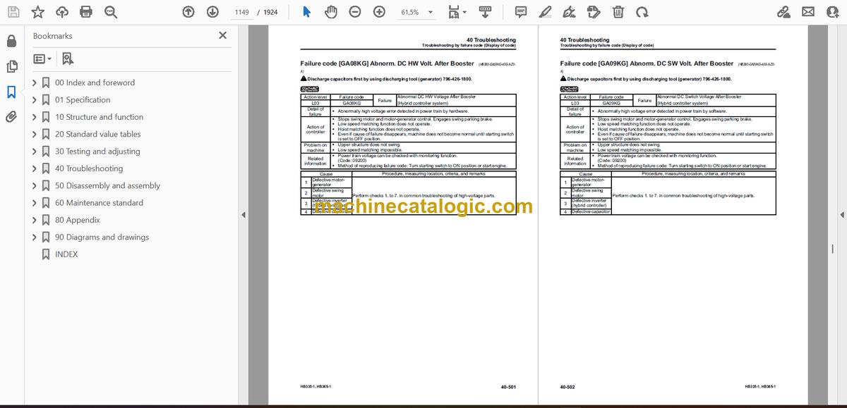
- Failure code [GA08KG] Abnorm. DC HW Volt. After Booster
- Failure code [GA09KG] Abnorm. DC SW Volt. After Booster
- Failure code [GA09KP] Low DC SW Output Volt. After Booster
- Failure code [GA0AKZ] DC Vlt. Sen. Op./Shrt Cir. Aft. Booster
- Failure code [GA0BKZ] AC Line Open & Short Circuit
- Failure code [GA10MC] HYB Controller Error
- Failure code [GA12NK] High-Voltage Line Start-up Failure
- Failure code [GA12NL] High-Voltage Line Discharge Failure
- Failure code [GA13MC] HYB Control. Sen. Power Sup. Failure
- Failure code [GA15KZ] HYB Cont. Bad Insul. Sen. Opn/Short. Cir
- Failure code [GA17KR] Gen. Mot. Drv. Communication Failure
- Failure code [GA17KY] Gen. Mot Dr. Power Line Short Circuit
- Failure code [GA17MB] Gen. Mot. Drv. Function Degraded
- Failure code [GA18MC] Gen. Mo.Dr. Excite. Pow. Sup. Failure
- Failure code [GA19KR] Gen. Motor Driver Sub-CPU Comm. Failure
- Failure code [GA19KT] Int. Abnorm. Gen. Mot. Drv. Sub-CPU Con.
- Failure code [GA19MA] Gen. Mot. Drv. Sub-CPU Malfunction
- Failure code [GA1BMA] Gen. Mot. Dr. DC Vlt. Sens. Malfunction
- Failure code [GA1FKR] Swing Mot. Drv. Communication Failure
- Failure code [GA1FMA] Abnormal Swing Motor Driver
- Failure code [GA1GKR] Swg Mot. Driver Sub-CPU Comm. Failure
- Failure code [GA1GKT] Swing Mot. Drv. Sub-CPU Cont. Abnormal
- Failure code [GA1GMA] Swing Motor Drv. Sub-CPU Malfunction
- Failure code [GA1GMB] Swing Mot. Drv. Sub-CPU Funct. Degraded
- Failure code [GA1HKZ] Swg Mot. Dr. Ph-U Tem. Sens Opn/Shrt Cir
- Failure code [GA1JKZ] Swg Mot. Dr. Ph-V Tem. Sens Opn/Shrt Cir
- Failure code [GA1KKZ] Swg Mot. Dr. Ph-W Tem. Sens Opn/Shrt Cir
- Failure code [GA1LKZ] Swg Mot. Dr. Current. Sens. Opn/Shrt Cir
- Failure code [GA1MKZ] Swg Mot. Dr. DC Vlt. Sen. Opn/Shrt Cir.
- Failure code [GA1NNS] Swing Motor Driver IGBT Overheat
- Failure code [GA1SFS] Contactor Locked
- Failure code [GA1SMC] Contactor Failure
- Failure code [GA1TKP] Capacitor Low Output Voltage
- Failure code [GA1TNS] Capacitor Overheat
- Failure code [GA1UKZ] Capacitor Temp. Sensor Opn/short Cir.
- Failure code [GA1VFS] Capacitor Contactor Locked
- Failure code [GA1VMC] Capacitor Contactor Failure
- Failure code [GA1XKZ] Boost. Ind. Temp. Sens. Open/Shrt. Circ.
- Failure code [GA1YNS] Booster Inductor Overheat
- Failure code [GA1ZKZ] Booster IGBT Temp. Sens. Opn/Shrt. Circ.
- Failure code [GA1ZNS] Booster IGBT Temp. Sens. Overheat
- Failure code [GA21KB] Booster IGBT Short Circuit
- Failure code [GA22NS] Booster IGBT Junction Overheat
- Failure code [GA23KZ] Gen. Mot. Dr. Temp. Sen.0 Opn/Short Cir.
- Failure code [GA24KZ] Gen. Mot. Dr. Temp. Sen.1 Opn/Short Cir.
- Failure code [GA25MA] Gen. Motor Driver IGBT 0 Abnormality
- Failure code [GA25NS] Gen. Motor Driver IGBT 0 Overheat
- Failure code [GA26MA] Gen. Motor Driver IGBT 1 Abnormality
- Failure code [GA26NS] Gen. Motor Driver IGBT 1 Overheat
- Failure code [GA27KZ] DC Cur. Sens. Bef. Booster Opn/Short Cir
- Failure code [GA28KZ] DC Cur. Sens. Aft. Booster Opn/Short Cir
- Failure code [GA2QKR] CAN2 Discon (Hyb Con)
- Failure code [GA2RKR] CAN1 Discon (Hyb Con)
- Failure code [GA60MC] Generator Motor Failure
- Failure code [GA60N1] Generator Motor Overrun
- Failure code [GA61KZ] Gen. Motor Temp. Sens. Opn/Short Cir.
- Failure code [GA61NS] Generator Motor Temp. Sensor Overheat
- Failure code [GA62KY] Gen. Mot. Ph-A Cur. Sen. Power Short Cir
- Failure code [GA62KZ] Gen. Mot. Ph-A Cur. Sen. Open/Short Cir
- Failure code [GA62MA] Gen. Mot. Ph-A Current Sen. Malfunction
- Failure code [GA63KY] Gen. Mot. Ph-B Cur. Sen. Power Short Cir
- Failure code [GA63KZ] Gen. Mot. Ph-B Cur. Sen. Open/Short Cir
- Failure code [GA63MA] Gen. Mot. Ph-B Current Sen. Malfunction
- Failure code [GA64KY] Gen. Mot. Ph-C Cur. Sen. Power Short Cir
- Failure code [GA64KZ] Gen. Mot. Ph-C Cur. Sen. Open/Short Cir
- Failure code [GA64MA] Gen. Mot. Ph-C Current Sen. Malfunction
- Failure code [GA70KB] HYB Swing Motor Short Circuit
- Failure code [GA70MD] HYB Swing Motor Defective Stirr. Motion
- Failure code [GA70NS] HYB Swing Motor Overheat
- Failure code [GA71KZ] HYB Swing Mot. Temp. Sens. Opn/Shrt Cir.
- Failure code [GA72MA] HYB Swing Motor Resolver Malfunction
- Failure code [GA72MC] HYB Swing Motor Resolver Defect Op.
- Failure code [GA81KZ] Swing Motor Power Cable Opn/Shrt Circ.
- Failure code [GAA0KB] HYB Con. Battery Relay Drive Short Cir.
- Failure code [GAA100] Swing Emergency Stop Operation
- Failure code [GAA2KB] Swing Brake Sol. Supply Line Short Cir.
- Troubleshooting of electrical system (E-mode)
- E-1 Engine does not start (Engine does not crank)
- E-2 Manual preheating system does not work
- E-3 Automatic preheating system does not work
- E-4 While preheating is working, preheating monitor does not light up
- E-5 When starting switch is turned to ON position, machine monitor displays nothing
- E-6 While starting switch is turned to ON position (with engine stopped), engine oil level monitor lights up in yellow
- E-7 While starting switch is turned to ON position (with engine stopped), radiator coolant level monitor lights up in yellow
- E-8 Engine coolant temperature monitor lights up in white while engine is running
- E-9 Hydraulic oil temperature monitor lights up in white while engine is running
- E-10 Charge level monitor lights up in red while engine is running
- E-11 Fuel level monitor lights up in red while engine is running
- E-12 Air cleaner clogging monitor lights up in yellow while engine is running
- E-13 Engine coolant temperature monitor lights up in red while engine is running
- E-14 Hydraulic oil temperature monitor lights up in red while engine is running
- E-15 Engine oil pressure monitor lights up in red while engine is running
- E-16 Fuel gauge display does not move from minimum or maximum
- E-17 Fuel gauge indicates incorrect amount
- E-18 Engine coolant temperature gauge display does not move from minimum or maximum
- E-19 Engine coolant temperature gauge indicates incorrect temperature
- E-20 Hydraulic oil temperature gauge display does not move from minimum or maximum
- E-21 Hydraulic oil temperature gauge indicates incorrect temperature
- E-22 Hybrid temperature gauge does not indicate correct temperature
- E-23 Some areas of machine monitor screen are not displayed
- E-24 Function switch does not work
- E-25 Automatic warm-up system does not operate (in cold season)
- E-26 Auto-deceleration monitor does not light up, or does not go out, while auto-deceleration switch is operated
- E-27 Auto-deceleration function does not operate or is not canceled while lever is operated
- E-28 Working mode selection screen is not displayed while working mode selector switch is operated
- E-29 Setting of engine and hydraulic pump is not changed while working mode is changed
- E-30 Travel speed monitor does not change when travel speed switch is operated
- E-31 Travel speed does not change while travel speed selection is changed
- E-32 Alarm buzzer does not stop sounding
- E-33 Service meter is not displayed, while starting switch is in OFF position
- E-34 Service mode cannot be selected
- E-35 Any of work equipment, swing and travel does not work
- E-36 Any of work equipment, swing and travel cannot be locked
- E-37 Upper structure does not swing while swing parking brake cancel switch is set to CANCEL position
- E-38 Swing brake does not operate while swing parking brake cancel switch is set to NORMAL position
- E-39 One-touch power maximizing function does not operate properly, or indicator is not displayed on monitor
- E-40 One-touch power maximizing function cannot be canceled
- E-41 Alarm does not sound during travel
- E-42 Alarm does not stop sounding while machine is stopped
- E-43 Horn does not sound
- E-44 Horn does not stop sounding
- E-45 Wiper monitor does not light up, or does not go out, while wiper switch is operated
- E-46 Wiper does not operate while wiper switch is operated
- E-47 Window washer does not operate while window washer switch is operated
- E-48 Boom LOWER is not displayed correctly with monitoring function
- E-49 Arm OUT is not displayed correctly with monitoring function
- E-50 Arm IN is not displayed correctly with monitoring function
- E-51 Boom RAISE is not displayed correctly with monitoring function
- E-52 Bucket CURL is not displayed correctly with monitoring function
- E-53 Bucket DUMP is not displayed correctly with monitoring function
- E-54 Swing is not displayed correctly with monitoring function
- E-55 Travel is not displayed correctly with monitoring function
- E-56 Service is not displayed correctly with monitoring function
- E-57 Attachment hydraulic circuit cannot be changed
- E-58 KOMTRAX system does not operate normally
- E-59 Machine push-up function is not canceled
- E-60 Machine push-up function does not operate
- Troubleshooting of hydraulic and mechanical system (H-mode)
- Information described in troubleshooting table (H-mode)
- System chart of hydraulic and mechanical systems
- Failure mode and cause table
- H-1 All of work equipments and travel operations lack speed or power
- H-2 Engine speed drops significantly or engine stalls
- H-3 Any of work equipment and travel does not work
- H-4 Unusual sound is heard from around hydraulic pump
- H-5 Fine control performance or response is poor
- H-6 Boom speed or power is low
- H-7 Arm speed or power is low
- H-8 Bucket speed or power is low
- H-9 Work equipment does not move in single operation
- H-10 Hydraulic drift of boom is large
- H-11 Hydraulic drift of arm is large
- H-12 Hydraulic drift of bucket is large
- H-13 Time lag of work equipment is large
- H-14 When part of work equipment is relieved singly, other parts of work equipment move
- H-15 One-touch power maximizing function does not work
- H-16 Machine push up function does not work
- H-17 In combined operation of work equipment, equipment having heavier load moves slower
- H-18 Machine does not travel straight
- H-19 Travel speed is slow
- H-20 Machine is hard to steer or travel power is low
- H-21 Travel speed does not change, or travel speed is too slow or fast
- H-22 One of tracks does not run
- H-23 Upper structure does not swing to the right or left
- H-24 Upper structure swing only to the right or left
- H-25 Swing acceleration or swing speed is low in both directions (right and left)
- H-26 Swing acceleration performance is poor or swing speed is slow in only one direction
- H-27 Upper structure overruns excessively when it stops swinging (both right and left)
- H-28 Upper structure overruns excessively when it stops swinging (either right or left)
- H-29 Shock is large when upper structure stops swinging
- H-30 Large unusual noise is heard when upper structure stops swinging
- H-31 Swing drift on a slope is large while swing parking brake is applied
- H-32 Swing drift on a slope is large while swing parking brake is released
- H-33 Attachment hydraulic circuit cannot be changed while attachment is installed
- H-34 Oil flow in attachment circuit cannot be controlled
- Troubleshooting of engine (S-mode)
- Information contained in troubleshooting table (S mode)
- S-1 Engine does not crank when starting switch is turned to START position
- S-2 The engine cranks but exhaust smoke does not come out
- S-3 Fuel is being injected but engine does not start (incomplete combustion: engine cranks but does not start)
- S-4 Engine startability is poor
- S-5 Engine does not pick up smoothly
- S-6 Engine stops during operation
- S-7 Engine runs rough or is unstable
- S-8 Engine lacks power
- S-9 Exhaust smoke is black
- S-10 Engine oil consumption is excessive
- S-11 Oil becomes contaminated quickly
- S-12 Fuel consumption is excessive
- S-13 Oil is in coolant (or coolant spurts or coolant level goes down)
- S-14 Oil pressure drops
- S-15 Fuel mixes into engine oil
- S-16 Water mixes into engine oil (milky)
- S-17 Coolant temperature rises too high (overheating)
- S-18 Unusual noise is heard
- S-19 Vibration is excessive
- S-20 Air cannot be bled from fuel circuit
- Troubleshooting for hybrid systems (Y mode)
- Precautions related to hybrid equipment
- Y-1 Hybrid monitor does not go out
- Y-2 Machine does not swing
- Y-3 Swing acceleration or swing speed is low
- Y-4 Upper structure overruns excessively when it stops swinging
- Y-5 Shock is large when upper structure stops swinging
- Y-6 Large unusual noise is heard when upper structure stops swinging
- Y-7 Swing drift on a slope is large
- Y-8 Electric swing motor temperature increases abnormally
- Y-9 Motor-generator temperature increases abnormally
- Y-10 Inverter temperature increases abnormally
- Y-11 Capacitor temperature increases abnormally
- 50 Disassembly and assembly
- Table of contents
- Related information on disassembly and assembly
- How to read this manual
- Precautions related to hybrid equipment
- Coating materials list
- Special tools list
- Sketches of special tools
- Engine and cooling system
- Removal and installation of supply pump assembly
- Removal and installation of injector assembly
- Removal and installation of cylinder head assembly
- Removal and installation of radiator assembly
- Removal and installation of hydraulic oil cooler assembly
- Removal and installation of aftercooler core
- Removal and installation of engine, motor-generator, and main pump assembly
- Removal and installation of fan belt
- Removal and installation of alternator belt
- Removal and installation of engine front oil seal
- Removal and installation of engine rear oil seal
- Removal and installation of fuel tank assembly
- Removal and installation of air cleaner assembly
- Removal and installation of air conditioner compressor assembly
- Removal and installation of air conditioner condenser assembly
- Removal and installation of EGR (Exhaust Gas Recirculation) valve assembly
- Removal and installation of EGR (Exhaust Gas Recirculation) cooler assembly
- Hybrid system
- Draining coolant, refilling with coolant, and bleeding air for hybrid system
- Removal and installation of hybrid system radiator assembly
- Removal and installation of hybrid system water pump assembly
- Removal and installation of inverter assembly
- Removal and installation of inverter and capacitor assembly
- Procedure for draining and refilling generator lubricating oil
- Removal and installation of motor-generator and housing assembly
- Removal and installation of electric swing motor assembly
- Power train system
- Removal and installation of travel motor and final drive assembly
- Disassembly and assembly of final drive assembly
- Removal and installation of electric swing motor and swing machinery assembly
- Disassembly and assembly of swing machinery assembly
- Removal and installation of swing circle assembly
- Undercarriage and frame
- Separation and connection of track shoe assembly
- Removal and installation of sprocket
- Removal and installation of idler and idler cushion assembly
- Disassembly and assembly of idler
- Disassembly and assembly of idler cushion assembly
- Disassembly and assembly of track roller assembly
- Disassembly and assembly of carrier roller assembly
- Removal and installation of revolving frame assembly
- Removal and installation of counterweight assembly
- Hydraulic system
- Removal and installation of center swivel joint assembly
- Disassembly and assembly of center swivel joint assembly
- Removal and installation of hydraulic tank assembly
- Removal and installation of main pump assembly
- Removal and installation of control valve assembly
- Disassembly and assembly of control valve assembly
- Procedure for replacing pressure compensation valve seal
- Assembly of control valve assembly
- Disassembly and assembly of work equipment PPC valve assembly
- Disassembly and assembly of travel PPC valve assembly
- Work equipment
- Removal and installation of bucket assembly
- Removal and installation of arm assembly
- Removal and installation of work equipment assembly
- Disassembly and assembly of work equipment cylinder assembly
- Cab and its attachments
- Removal and installation of operator's cab assembly
- Removal and installation of operator's cab glass (adhered glass)
- Removal and installation of front window assembly
- Removal and installation of floor frame assembly
- Removal and installation of air conditioner unit assembly
- Removal and installation of operator's seat
- Removal and installation of seat belt
- Removal and installation of work equipment control lever assembly
- Removal and installation of front wiper assembly
- Electrical system
- Removal and installation of engine controller assembly
- Removal and installation of pump controller assembly
- Removal and installation of machine monitor assembly
- Removal and installation of pump swash plate sensor
- Removal and installation of KOMTRAX terminal assembly
- 60 Maintenance standard
- Table of contents
- Engine and cooling system
- Engine mount
- Cooling system
- Power train system
- Swing circle
- Swing machinery with swing brake
- Final drive
- Sprocket
- Undercarriage and frame
- Track frame and idler cushion
- Idler
- Track roller
- Carrier roller
- Track shoe
- Hydraulic system
- Hydraulic tank
- Main pump
- Control valve
- Travel motor
- PPC valve
- Solenoid valve
- Attachment circuit selector valve
- Center swivel joint
- Work equipment
- Work equipment
- Work equipment cylinder
- 80 Appendix
- Table of contents
- Air conditioner components
- Precautions for refrigerant
- Air conditioner component
- Configuration and function of refrigeration cycle
- Outline of refrigeration cycle
- Air conditioner unit
- Dual pressure switch
- Air conditioner controller
- Compressor
- Condenser
- Receiver drier
- Sunlight sensor
- Outer temperature sensor (outside air temperature sensor)
- Procedure for testing and troubleshooting
- Circuit diagram and arrangement of connector pins
- System diagram
- Parts and connectors layout
- Testing air leakage (duct)
- Testing with self-diagnosis function
- Testing vent (mode) changeover
- Testing FRESH/RECIRC air changeover
- Testing sunlight sensor
- Testing (dual) pressure switch for refrigerant
- Testing relays
- Troubleshooting chart 1
- Troubleshooting chart 2
- Information in troubleshooting table
- Failure code list related to air conditioner
- Failure code [879AKA] A/C Inner sensor Open Circuit
- Failure code [879AKB] A/C Inner sensor Short Circuit
- Failure code [879BKA] A/C Outer sensor Open Circuit
- Failure code [879BKB] A/C Outer sensor Short Circuit
- Failure code [879CKA] Ventilating sensor Open Circuit
- Failure code [879CKB] Ventilating sensor Short Circuit
- Failure code [879DKZ] Sunlight sensor Open or Short Circuit
- Failure code [879EMC] Ventilating Damper Abnormality
- Failure code [879FMC] Air Mix Damper Abnormality
- Failure code [879GKX] Refrigerant Abnormality
- A-1 Troubleshooting for power supply system (Air conditioner does not operate)
- A-2 Troubleshooting for compressor and refrigerant system (Air is not cooled)
- A-3 Troubleshooting for blower motor system (No air comes out or air flow is abnormal)
- A-4 Troubleshooting for FRESH/RECIRC air changeover
- Troubleshooting with gauge pressure
- Connection of service tool
- Precautions for disconnecting and connecting air conditioner piping
- Handling of compressor oil
- 90 Diagrams and drawings
- Table of contents
- Hydraulic circuit diagram
- Symbols in hydraulic circuit diagram
- Hydraulic circuit diagram
- Electric circuit diagram
- Symbols in electric circuit diagram
- Electrical circuit diagram
- Electrical circuit diagram of air conditioner unit
- INDEX
Komatsu


