Format: PDF (Printable Document)
File Language: English
File Pages: 121
File Size: 7.77 MB (Speed Download Link)
Brand: Komatsu
Model: PC360LC-11, PC360LC-11E0 Hydraulic Excavator
Book No: GEN00263-01
Serial No: 90001, 92143 and up
Type of Document: Field Assembly Manual
$ 39
FOREWORD
CONTENTS
Specifications
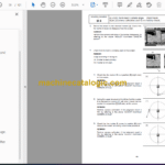
Precautions for field assembly
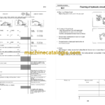
Disposal of removed parts
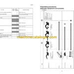
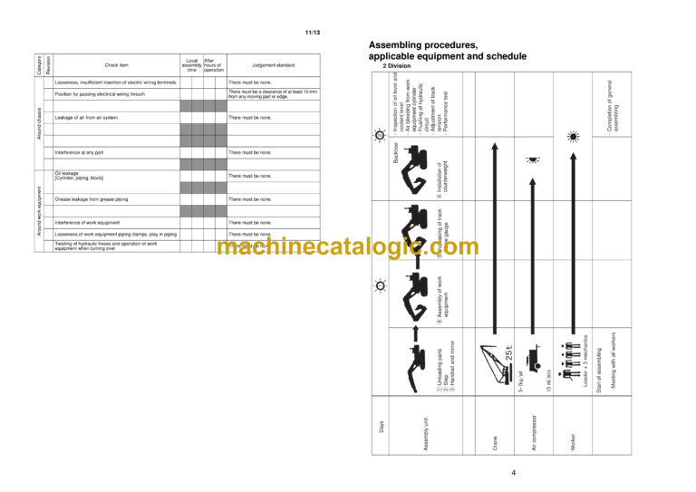
Assembling procedures, applicable equipment and schedule
Flow of field assembly
KIT layout diagram
Transportation
Tool list for field assembly
Tightening torque
Coating materials
Selection of wire ropes used for assembly
Selection of nylon slings used for assembly
A. Assembly of chassis
A- 1. Installation of handrail
A- 2. Installation of climbing grip
A- 3. Installation of mirror
B. Assembling of work equipment
B- 1. Installation of arm assembly
B- 2. Releasing remaining pressure in hydraulic circuit
B- 3. Installation of bucket cylinder hoses between boom and bucket cylinder
B- 4. Installation of bucket
B- 5. Greasing after completion of work equipment
B- 6. Bleeding air from work equipment circuit
C. Increasing and decreasing oF track frame gauge, assembling of counterweight
C- 1. Adjustment of track tension
C- 2. Sticking sheet to revolving frame
C- 3. Sticking sheet to counterweight
C- 4. Installation of camera
C- 5. Installation of counterweight
M. Procedure for inspection and maintenance after completion of a ssembly
M- 1. Replacement of return filter (Standard filter to flushing filter)
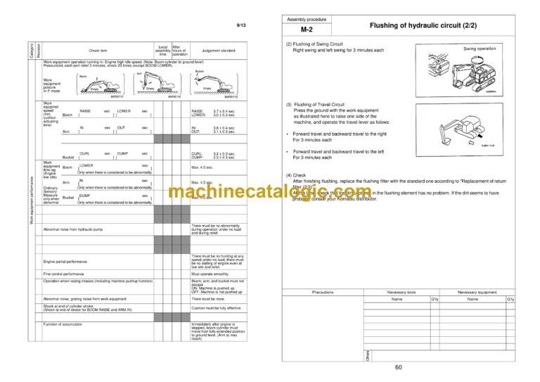
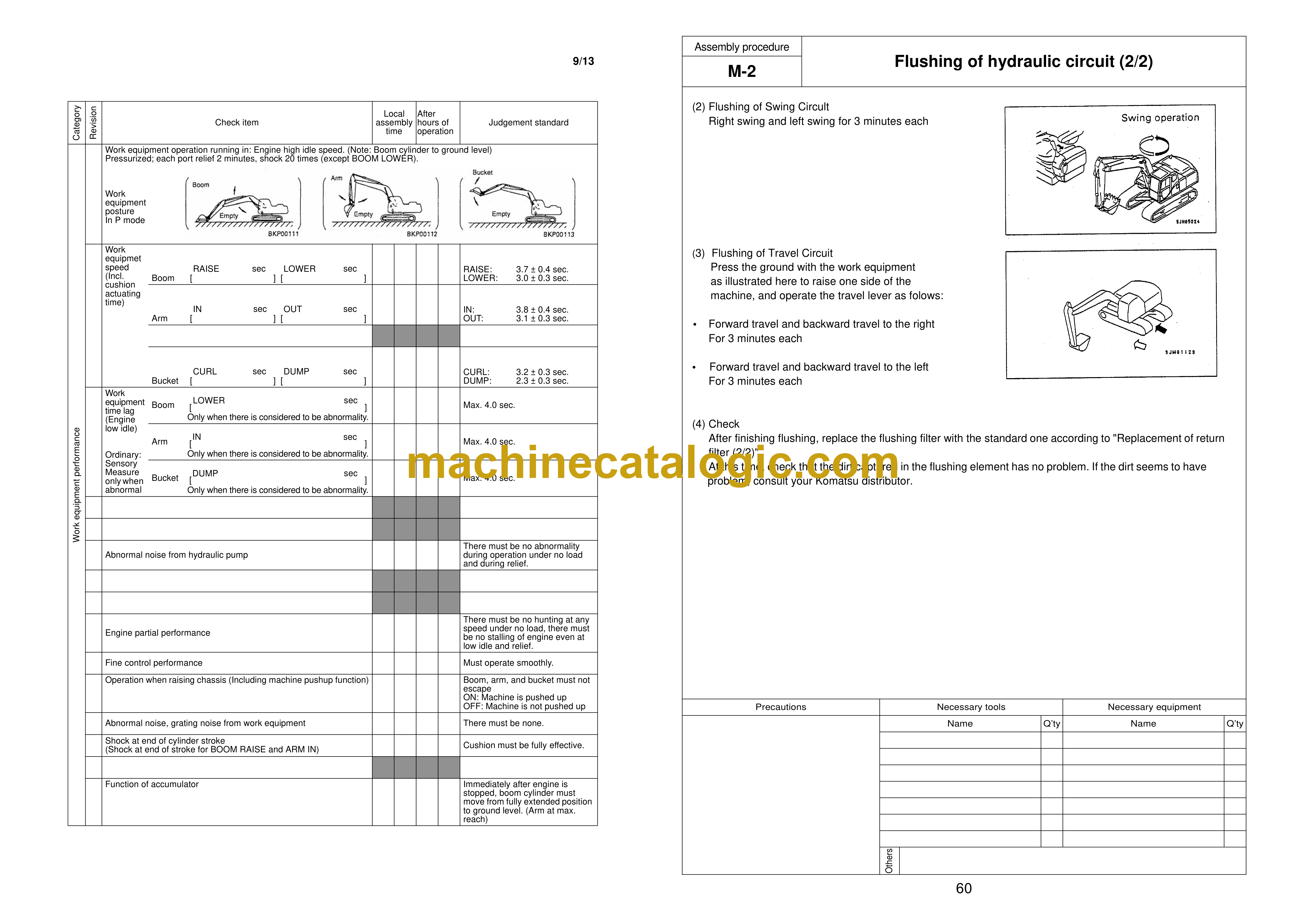
M- 2. Flushing of hydraulic circuit
M- 3. Replacement of return filter (Flushing filter to standard filter)
M- 4. Check of oil/coolant level at each part
M- 5. Inspection of oil level in hydraulic tank and refill
M- 6. Parts to be touched up after field assembly
M- 7. Error code
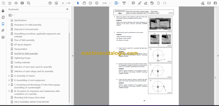
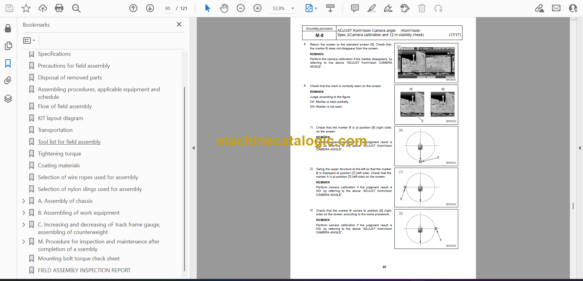
M- 8. ADJUST KomVision Camera angle(KomVision Spec.)
Mounting bolt torque check sheet
FIELD ASSEMBLY INSPECTION REPORT
—————————————-
1. Drawings of removed units (travel)
2. Dimensions of removed units (travel)
3. Drawings of removed units (non travel)
4. Dimensions of removed units (non travel)
5. Assembly procedure, necessary equipments, and schedule (travel)
6. Necessary tools and equipments (travel)
7. Assembly procedure, necessary equipments, and schedule (non travel)
8. Necessary tools and equipments (non travel)
8-1 How to secure machine
9. Assembly procedure
No. 0010 Installation of the sling
No. 0100 Stationary bare machine (travel)
No. 0101 Stationary bare machine (non-travel) (without front and rear wheels, dump body)
No. 0170 Installation of tire and wheel assembly
No. 0200 Unfolding of rearview mirror (non travel)
No. 0310 Installation of KOMTRAX antenna
No. 0315 Installation of radio antenna
No. 0320 Installation of payload meter and yellow revolving lamp
No. 0325 Installation of payload meter
No. 0400 ADT assembly – Bushing installation (optional)
No. 0410 ADT assembly – Side arm installation (optional)
No. 0415 ADT assembly – Assembling procedure of side arm mounting bolt
No. 0420 ADT assembly with tailgate (optional)
No. 0430 ADT assembly with tailgate (optional)
No. 0440 ADT assembly with tailgate (optional)
No. 0450 ADT assembly with tailgate (optional)
No.0460 ADT assembly – Lubrication piping installation
No. 0530 Installation of R.H. fender mudguard
No. 0540 Installation of L.H. fender mudguard
No. 0600 Leveling procedure for machine rear section (packing style without dump body or with dump body packed separately)
No. 0610 Sling and put stationary dump body
No. 0620 Assembly of dump body subassembly
No. 0630 Installation of dump body
No. 0640 Connection of hoist cylinder
No. 0643 Installation of hoist pipe guard R.H.
No. 0644 Installation of hoist pipe guard L.H.
No. 0650 Installation and adjustment of dump angle sensor
No. 0660 Installation and adjustment of dump body bottom mounting
No. 0670 Installation of dump body stopper
No. 0675 Adjustment procedure for exhaust box stroke (Specification with dump body heater)
No. 0680 Installation of the blind bolt and washer after installing the dump body
No.0685 Dump body control calibration
No. 0690 Sticking of decal on dump body
No. 0695 Sticking of decal on dump body (optional)
No. 0696 Installation of tie-off bracket (packing style without dump body or with dump body packed separately)
No. 0697 Sticking of certificate decals (dump body) for KAL
No. 0700 Touch up painting of dump body
No. 0710 Adjustment-1 of rearview monitor
No. 0711 Adjustment-2 of rearview monitor
No. 0712 Adjustment-3 of rearview monitor
No. 0713 Adjustment-4 of rearview monitor
No. 0800 Nitrogen gas adjustment of front and rear suspensions
No. 0810 Method for checking and inflating tire
Appendix
Adjustment of mirror
Machine check sheet for field assembly
