These Komatsu PC850-8, PC850SE-8 Crawler Excavators are big production machines—mass excavation, quarry faces, heavy demolition, and feeding crushers. People who reach for the Komatsu PC850-8, PC850SE-8 Crawler Excavator Shop Manual (SEN00373-24) are usually shop mechanics, senior techs, or fleet managers who plan repairs instead of reacting to breakdowns. They’re trying to cut dealer callouts, standardize procedures, and keep parts and labor lined up with the work schedule.
What this manual helps you do
- Trace hydraulic issues on a large multi-pump system using factory troubleshooting flows and circuit information.
- Diagnose engine, fuel, and electronic control problems with step-by-step test sequences that most shops can follow with standard tools.
- Follow correct teardown and reassembly procedures for major components like final drives, swing machinery, and cylinders.
- Check adjustment procedures for items like travel system components, swing, and attachment functions so the machine works within spec.
- Verify which fasteners, fluids, and adjustments go where during workshop-level repairs, so you don’t guess or mix methods between units.
Who this is for
This is aimed at field techs, shop mechanics, and fleet managers who plan and execute mid‑ to heavy‑level repairs on their own. If you’re just looking for daily checks, basic maintenance intervals, or operating tips, you’d be better off with the Operation & Maintenance Manual instead.
FAQ
Q: Is this a searchable PDF I can print from?
A: Yes, this type of shop manual is normally provided as a searchable PDF that you can print sections from as needed in the shop.
Q: Does it go deep enough for full component rebuilds?
A: The Shop Manual for Komatsu PC850-8, PC850SE-8 Crawler Excavator walks through diagnostic procedures, disassembly sequences, and reference data used during workshop-level repairs. It’s meant for full system and component work, not just light service.
Q: How do I know it matches my exact machine version?
A: You’ll want to match your machine’s identification plate to the SEN00373-24 book reference and confirm with your dealer if you’re near a model or emission-change boundary.
Bottom line: if you’re planning to keep a PC850-8 or PC850SE-8 in your fleet and handle most repairs in-house, this is the right manual; if you only do basic servicing and leave repairs to the dealer, you can probably skip it.
📘 Show Index
Table of Contents:
- 00 Index and foreword
- Index
- Composition of shop manual
- Table of contents
- Foreword and general information
- Safety notice
- How to read the shop manual
- Explanation of terms for maintenance standard
- Handling of electric equipment and hydraulic component
- Handling of connectors newly used for engines
- How to read electric wire code
- Precautions when carrying out operation
- Method of disassembling and connecting push-pull type coupler
- Standard tightening torque table
- Conversion table
- 01 Specification
- Specification and technical data
- Specification and technical data
- Specification drawings
- Working range drawing
- Specifications
- Weight table
- Table of fuel, coolant and lubricants
- 10 Structure, function and maintenance standard
- Engine and cooling system
- Engine and cooling system
- Coupling
- Coupling lubrication system
- Radiator, oil cooler
- Power train
- Power train
- Power train
- Swing machinery
- Swing circle
- Final drive
- Sprocket
- Undercarriage and frame
- Undercarriage and frame
- Track frame and recoil spring
- Idler
- Carrier roller
- Track roller
- Track shoe
- Hydraulic system, Part 1
- Hydraulic system, Part 1
- Hydraulic piping drawing
- Hydraulic tank, hydraulic filter
- Hydraulic pump
- Cooling fan pump
- Cooling fan motor
- Hydraulic system, Part 2
- Hydraulic system, Part 2
- Motor grease pump
- Return oil filter
- Line oil filter
- Drain oil filter
- L.H. 5-Spool control valve
- R.H. 4-Spool control valve
- Straight-travel valve
- Swing motor
- Center swivel joint
- Travel motor
- PPC accumulator
- Work equipment, swing PPC valve
- Travel PPC valve
- Anti-drop valve
- Solenoid valve
- Quick return valve
- Hydraulic cylinder
- Work equipment
- Work equipment
- Work equipment
- Dimensions of work equipment
- Cab and its attachments
- Electrical system
- Engine control
- Electric control system
- Monitor system
- Sensors
- KOMTRAX system
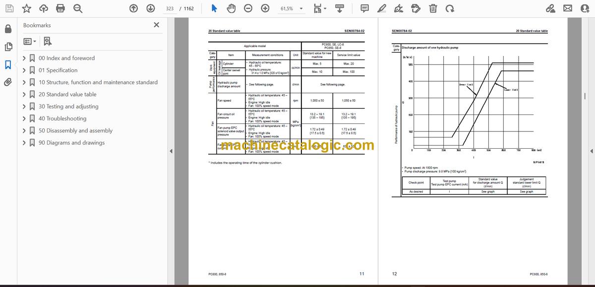
- 20 Standard value table
- Standard service value table
- Standard service value table
- Standard service value table for engine
- Standard service value table for chassis
- 30 Testing and adjusting
- Testing and adjusting, Part 1
- Testing and adjusting, Part 1
- Tools for testing, adjusting and troubleshooting
- Measuring engine speed
- Measuring intake air pressure (Boost pressure)
- Measuring exhaust gas temperature
- Measuring exhaust gas color
- Adjusting valve clearance
- Measuring compression pressure
- Measuring blow-by pressure
- Measuring engine oil pressure
- Measuring EGR valve and bypass valve drive pressure
- Handling of fuel system equipment
- Remaining pressure relief from fuel system equipment
- Measuring fuel pressure
- Testing fuel return rate and leakage
- Bleeding air from fuel circuit
- Testing fuel system for leakage
- Testing and adjusting alternator belt tension
- Testing and adjusting air conditioner compressor belt
- Testing and adjusting, Part 2
- Testing and adjusting, Part 2
- Inspection of swing circle bearing clearance
- Testing and adjusting track shoe tension
- Testing and adjusting work equipment, swing, and travel circuit oil pressures
- Testing and adjusting control circuit pressure (output pressure of self pressure reducing valve)
- Testing and adjusting main pump control pressure
- Testing and adjusting, Part 3
- Testing and adjusting, Part 3
- Measuring PPC valve output pressure
- Measuring outlet pressures of solenoid valve, swing PPC shuttle valve, and swing priority selector valve
- Adjusting work equipment, swing PPC valve
- Testing and adjusting travel deviation
- Inspection of locations of hydraulic drift of work equipment
- Measuring fan speed
- Measuring fan circuit oil pressure
- Measuring fan pump EPC current
- Measuring fan pump EPC solenoid valve output pressure
- Measuring oil leakage
- Release of residual pressure from hydraulic circuit
- Bleeding air from each part
- Inspection procedures for diode
- Adjusting mirrors
- Testing and adjusting, Part 4
- Testing and adjusting, Part 4
- Special function of machine monitor
- Handling controller voltage circuit
- Testing and adjusting, Part 5
- Testing and adjusting, Part 5
- Procedure for turning on KOMTRAX terminal
- KOMTRAX terminal lamp indications
- Preparation work for troubleshooting electrical system
- Pm-clinic service
- 40 Troubleshooting
- Failure code table and fuse locations
- Failure code table and fuse locations
- Failure codes table
- Fuse locations
- General information on troubleshooting
- General information on troubleshooting
- Points to remember when troubleshooting
- Sequence of events in troubleshooting
- Checks before troubleshooting
- Checking water pump for water leakage
- Classification and troubleshooting steps
- Information in troubleshooting table
- Failure-looking phenomenon and troubleshooting No.
- Connection table for connector pin numbers
- T- branch box and T- branch adapter table
- Troubleshooting by failure code (Display of code), Part 1
- Troubleshooting by failure code (Display of code), Part 1
- Failure code [AA10NX] Aircleaner Clogging
- Failure code [AB00KE] Charge Voltage Low
- Failure code [B@BAZG] Eng. Oil Press. Low
- Failure code [B@BAZK] Eng. Oil Level Low
- Failure code [B@BCNS] Eng. Water Overheat
- Failure code [B@BCZK] Eng. Water Lvl Low
- Failure code [B@HANS] Hydr. Oil Overheat
- Failure code [CA111] ECM Critical Internal Failure
- Failure code [CA115] Eng Ne and Bkup Speed Sens Error
- Failure code [CA122] Chg Air Press Sensor High Error
- Failure code [CA123] Chg Air Press Sensor Low Error
- Failure code [CA131] Throttle Sensor High Error
- Failure code [CA132] Throttle Sensor Low Error
- Failure code [CA135] Eng Oil Press Sensor High Error
- Failure code [CA141] Eng Oil Press Sensor Low Error
- Failure code [CA144] Coolant Temp Sens High Error
- Failure code [CA145] Coolant Temp Sens Low Error
- Failure code [CA153] Chg Air Temp Sensor High Error
- Failure code [CA154] Chg Air Temp Sensor Low Error
- Failure code [CA187] Sens Supply 2 Volt Low Error
- Failure code [CA221] Ambient Press Sens High Error
- Failure code [CA222] Ambient Press Sens Low Error
- Failure code [CA227] Sens Supply 2 Volt High Error
- Failure code [CA234] Eng Overspeed
- Failure code [CA238] Ne Speed Sens Supply Volt Error
- Failure code [CA263] Fuel Temp Sensor High Error
- Failure code [CA265] Fuel Temp Sensor Low Error
- Failure code [CA271] IMV/PCV1 Short Error
- Failure code [CA272] IMV/PCV1 Open Error
- Failure code [CA273] PCV2 Short Error
- Failure code [CA274] PCV2 Open Error
- Failure code [CA322] Inj #1 (L#1) Open/Short Error
- Failure code [CA323] Inj #5 (L#5) Open/Short Error
- Failure code [CA324] Inj #3 (L#3) Open/Short Error
- Failure code [CA325] Inj #6 (L#6) Open/Short Error
- Failure code [CA331] Inj #2 (L#2) Open/Short Error
- Failure code [CA332] Inj #4 (L#4) Open/Short Error
- Failure code [CA342] Calibration Code Incompatibility
- Failure code [CA351] Injectors Drive Circuit Error
- Failure code [CA352] Sens Supply 1 Volt Low Error
- Failure code [CA386] Sens Supply 1 Volt High Error
- Troubleshooting by failure code (Display of code), Part 2
- Troubleshooting by failure code (Display of code), Part 2
- Failure code [CA441] Battery Voltage Low Error
- Failure code [CA442] Battery Voltage High Error
- Failure code [CA449] Rail Press Very High Error
- Failure code [CA451] Rail Press Sensor High Error
- Failure code [CA452] Rail Press Sensor Low Error
- Failure code [CA553] Rail Press High Error
- Failure code [CA554] Rail Press Sensor In Range Error
- Failure code [CA559] Rail Press Low Error
- Failure code [CA689] Eng Ne Speed Sensor Error
- Failure code [CA731] Eng Bkup Speed Sens Phase Error
- Failure code [CA757] All Persistent Data Lost Error
- Failure code [CA778] Eng Bkup Speed Sensor Error
- Failure code [CA1228] EGR Valve Servo Error 1
- Failure code [CA1625] EGR Valve Servo Error 2
- Failure code [CA1626] BP Valve Sol Current High Error
- Failure code [CA1627] BP Valve Sol Current Low Error
- Failure code [CA1628] Bypass Valve Servo Error 1
- Failure code [CA1629] Bypass Valve Servo Error 2
- Failure code [CA1631] BP Valve Pos Sens High Error
- Failure code [CA1632] BP Valve Pos Sens Low Error
- Failure code [CA1633] KOMNET Datalink Timeout Error
- Failure code [CA1642] EGR Inter Press Sens Low Error
- Failure code [CA1653] EGR Inter Press Sens High Error
- Failure code [CA2185] Throt Sens Sup Volt High Error
- Failure code [CA2186] Throt Sens Sup Volt Low Error
- Failure code [CA2249] Rail Press Very Low Error
- Failure code [CA2271] EGR Valve Pos Sens High Error
- Failure code [CA2272] EGR Valve Pos Sens Low Error
- Failure code [CA2351] EGR Valve Sol Current High Error
- Failure code [CA2352] EGR Valve Sol Current Low Error
- Failure code [CA2555] Grid Htr Relay Volt Low Error
- Failure code [CA2556] Grid Htr Relay Volt High Error
- Failure code [D110KB] Battery Relay Drive S/C
- Failure code [D163KB] Flash Light Relay S/C
- Failure code [D195KB] Step Light Relay S/C
- Failure code [DA22KK] Pump Solenoid Power Low Error
- Failure code [DA25KP] Press. Sensor Power Abnormality
- Failure code [DA2SKQ] Model Selection Abnormality
- Failure code [DA80MA] Auto. Lub. Abnormal.
- Failure code [DA2RMC] Pump Comm. Abnormality
- Failure code [DAFRMC] Monitor Comm. Abnormality
- Failure code [DGE5KY] Ambi. Temp. Sensor S/C
- Failure code [DGH2KB] Hydr. Oil Temp. Sensor S/C
- Troubleshooting by failure code (Display of code), Part 3
- Troubleshooting by failure code (Display of code), Part 3
- Failure code [DH25KA] L Jet Sensor Disc
- Failure code [DH25KB] L Jet Sensor S/C
- Failure code [DH26KA] R Jet Sensor Disc.
- Failure code [DH26KB] R Jet Sensor S/C
- Failure code [DHPEKA] F Pump P. Sensor Disc.
- Failure code [DHPEKB] F Pump P. Sensor S/C
- Failure code [DHPFKA] R Pump P. Sensor Disc.
- Failure code [DHPFKB] R Pump P. Sensor S/C
- Failure code [DV20KB] Travel Alarm S/C
- Failure code [DW41KA] Swing Priority Sol. Disc.
- Failure code [DW41KB] Swing Priority Sol. S/C
- Failure code [DW43KA] Travel Speed Sol. Disc.
- Failure code [DW43KB] Travel Speed Sol. S/C
- Failure code [DW45KA] Swing Brake Sol. Disc.
- Failure code [DW45KB] Swing Brake Sol. S/C
- Failure code [DW7BKA] Fan Reverse Sol. Disc.
- Failure code [DW7BKB] Fan Reverse Sol. S/C
- Failure code [DW7JKA] Bottom Dump Priority Sol. Disc.
- Failure code [DW7JKB] Bottom Dump Priority Sol. S/C
- Failure code [DWK0KA] 2-stage Relief Sol. Disc.
- Failure code [DWK0KB] 2-stage Relief Sol. S/C
- Failure code [DX16KA] Fan Pump EPC Sol. Disc.
- Failure code [DX16KB] Fan Pump EPC Sol. S/C
- Failure code [DXAAKA] F Pump EPC Sol. Disc.
- Failure code [DXAAKB] F Pump EPC Sol. S/C
- Failure code [DXABKA] R Pump EPC Sol. Disc.
- Failure code [DXABKB] R Pump EPC Sol. S/C
- Failure code [DY20KA] Wiper Working Abnormality
- Failure code [DY20MA] Wiper Parking Abnormality
- Failure code [DY2CKB] Washer Drive S/C
- Failure code [DY2DKB] Wiper Drive (For) S/C
- Failure code [DY2EKB] Wiper Drive (Rev) S/C
- Troubleshooting of electrical system (E-mode)
- Troubleshooting of electrical system (E-mode)
- Before carrying out troubleshooting of electrical system
- Information contained in troubleshooting table
- E-1 Engine does not start (Engine does not rotate)
- E-2 Preheater does not operate
- E-3 Auto engine warm-up device does not work
- E-4 Auto-decelerator does not operate
- E-5 All work equipment, swing and travel do not move
- E-6 Machine push-up function does not operate normally
- E-7 Boom shockless function does not operate normally
- E-8 Any item is not displayed on machine monitor
- E-9 Part of display on machine monitor is missing
- E-10 Machine monitor displays contents irrelevant to the model
- E-11 Fuel level monitor red lamp lights up while engine is running
- E-12 Engine coolant thermometer does not display normally
- E-13 Hydraulic oil temperature gauge does not display correctly
- E-14 Fuel gauge does not display correctly
- E-15 Swing lock monitor does not display correctly
- E-16 When monitor switch is operated, nothing is displayed
- E-17 Windshield wiper and window washer do not work
- E-18 “Boom RAISE” is not correctly displayed in monitor function
- E-19 “Boom LOWER” is not correctly displayed in monitor function
- E-20 “Arm IN” is not correctly displayed in monitor function
- E-21 “Arm OUT” is not correctly displayed in monitor function
- E-22 “Bucket CURL” is not correctly displayed in monitor function
- E-23 “Bucket DUMP” is not correctly displayed in monitor function
- E-24 “SWING” is not correctly displayed in monitor function
- E-25 “Left travel” is not displayed normally in monitoring function
- E-26 “Right travel” is not displayed normally in monitoring function
- E-27 “Service” is not correctly displayed in monitor function
- E-28 KOMTRAX system does not operate normally
- E-29 Air conditioner does not work
- E-30 Step light does not light up or go off
- E-31 Electric grease gun does not operate
- E-32 Travel alarm does not sound or does not stop sounding
- Troubleshooting of hydraulic and mechanical system (H-mode)
- Troubleshooting of hydraulic and mechanical system (H-mode)
- Before troubleshooting
- Information in troubleshooting table
- H-1 Speed or power of all work equipment, travel, and swing is low
- H-2 Engine speed lowers remarkably or engine stalls
- H-3 All work equipment, travel, and swing systems do not work
- H-4 Abnormal sound is heard from around pump
- H-5 Boom speed or power is low
- H-6 Speed or power of arm is low
- H-7 Speed or power of bucket is low
- H-8 Boom does not move
- H-9 Arm does not move
- H-10 Bucket does not move
- H-11 Hydraulic drift of work equipment is large
- H-12 Time lag of work equipment is large
- H-13 Heavy lift function does not operate or stop
- H-14 Machine push-up function does not operate or stop
- H-15 Boom shockless function cannot be turned ON or OFF
- H-16 Machine deviates in one direction
- H-17 Machine deviates largely at start
- H-18 Machine deviates largely during compound operation
- H-19 Travel speed or power is low
- H-20 Machine does not travel (only one track)
- H-21 Travel speed does not change
- H-22 Upper structure does not swing
- H-23 Swing speed or acceleration is low
- H-24 Swing speed or acceleration is low during compound operation of swing and work equipment
- H-25 Upper structure overruns excessively when it stops swinging
- H-26 Large shock is made when upper structure stops swinging
- H-27 Large abnormal sound is made when upper structure stops swinging
- H-28 Hydraulic drift of swing is large
- H-29 Fan rotation is abnormal (Fan sound/vibration is abnormally large or fan overheats)
- Troubleshooting of engine (S-mode)
- Troubleshooting of engine (S-mode)
- Method of using troubleshooting chart
- S-1 Starting performance is poor
- S-2 Engine does not start
- S-3 Engine does not pick up smoothly
- S-4 Engine stops during operations
- S-5 Engine does not rotate smoothly
- S-6 Engine lacks output (or lacks power)
- S-7 Exhaust gas color is black (incomplete combustion)
- S-8 Oil consumption is excessive (or exhaust smoke is blue)
- S-9 Oil becomes contaminated quickly
- S-10 Fuel consumption is excessive
- S-11 Oil is in coolant (or coolant spurts back or coolant level goes down)
- S-12 Oil pressure drops
- S-13 Oil level rises (Entry of coolant/fuel)
- S-14 Coolant temperature becomes too high (overheating)
- S-15 Abnormal noise is made
- S-16 Vibration is excessive
- 50 Disassembly and assembly
- General information on disassembly andassembly
- How to read this manual
- Coating materials list
- Special tools list
- Sketches of special tools
- Engine and cooling system (SAA6D140E-5)
- Engine and cooling system
- Removal and installation of engine, PTO and hydraulic pump assembly
- Removal and installation of cooling assembly
- Removal and installation of aftercooler assembly
- Removal and installation of fuel cooler and air conditioner condenser assembly
- Removal and installation of fan motor assembly
- Removal and installation of fuel tank assembly
- Engine (SAA6D140E-5)
- Removal and installation of fuel supply pump assembly
- Removal and installation of cylinder head assembly
- Removal and installation of fuel injector assembly
- Removal and installation of engine front seal
- Removal and installation of engine rear seal
- Power train
- Removal and installation of PTO (coupling) assembly
- Disassembly and assembly of PTO (coupling) assembly
- Removal and installation of swing motor and swing machinery assembly
- Disassembly and assembly of swing machinery assembly
- Removal and installation of swing circle assembly
- Disassembly and assembly of final drive assembly
- Undercarriage and frame
- Undercarriage and frame
- Removal and installation of trackshoe assembly
- Disassembly and assembly of one link in field
- Removal and installation of idler assembly
- Disassembly and assembly of idler assembly
- Disassembly and assembly of idler adjustment cylinder assembly
- Removal and installation of recoil spring assembly
- Disassembly and assembly of recoil spring assembly
- Removal and installation of carrier roller assembly
- Disassembly and assembly of carrier roller assembly
- Removal and installation of track roller assembly
- Disassembly and assembly of track roller assembly
- Removal and installation of revolving frame assembly
- Removal and installation of counterweight assembly
- Removal and installation of counterweight remover assembly
- Hydraulic system
- Removal and installation ofhydraulic tank assembly
- Removal and installation of mainpump assembly
- Removal and installation of mainpump input shaft oil seal
- Removal and installation ofcooling fan pump assembly
- Removal and installation ofcontrol valve assembly
- Assembly of control valveassembly
- Removal and installation of swingmotor assembly
- Removal and installation of centerswivel joint assembly
- Disassembly and assembly ofcenter swivel joint assembly
- Removal and installation of travelmotor assembly
- Removal and installation of solenoidvalve assembly
- Removal and installation of boomdamping valve assembly
- Disassembly and assembly ofwork equipment PPC valveassembly
- Disassembly and assembly oftravel PPC valve assembly
- Disassembly and assembly ofhydraulic cylinder assembly
- Disassembly and assembly ofgrease gun assembly
- Work equipment
- Work equipment
- Removal and installation of bucket cylinder assembly
- Removal and installation of arm cylinder assembly
- Removal and installation of boom cylinder assembly
- Removal and installation of bottom dump cylinder assembly
- Removal and installation of bucket assembly
- Removal and installation of arm assembly
- Removal and installation of boom assembly
- Removal and installation of work equipment
- Cab and its attachments
- Cab and its attachments
- Removal and installation of operator’s cab
- Removal and installation of operator’s cab glass (stuck glass)
- Removal and installation of front window assembly
- Removal and installation of work equipment control lever assembly
- Electrical system
- Electrical system
- Removal and installation of air conditioner unit assembly
- Removal and installation of engine controller assembly
- Removal and installation of monitor assembly
- Removal and installation of pump controller assembly
- Removal and Installation of KOMTRAX terminal assembly
- 90 Diagrams and drawings
- Hydraulic diagrams and drawings
- Hydraulic circuit diagram
- Electrical diagrams and drawings
- Electrical circuit diagram (1/5)
- Electrical circuit diagram (2/5)
- Electrical circuit diagram (3/5)
- Electrical circuit diagram (4/5)
- Electrical circuit diagram (5/5)
- Connector list and sterogram
Komatsu


