Format: PDF (Printable Document)
File Language: English
File Pages: 251
File Size: 28.58 MB (Speed Download Link)
Brand: Komatsu
Model: PC950-11E0 PC950LC-11E0 Hydraulic Excavator
Book No: GEN00268-03
Serial No: 10026 and up
Type of Document: Field Assembly Manual
$ 39
Preface
CONTENTS
Specifications
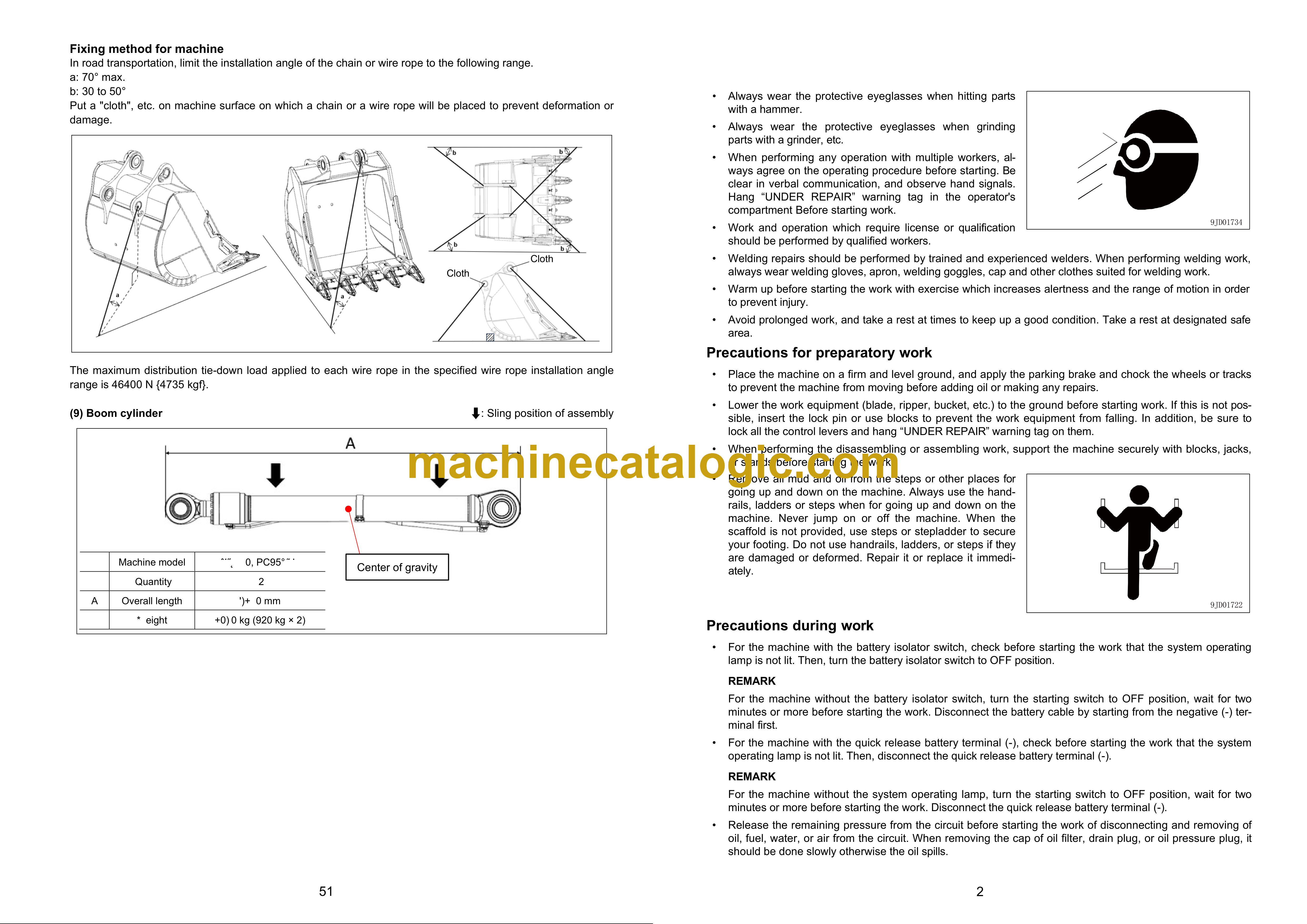
Precautions for field assembly
Disposal of removed parts
Assembly procedure, necessary equipment, and schedule
Layout of kit
Style for transportation
Table of tools for field assembly
Sketch of jigs
Tightening torque
Coating materials list
Selection of wire ropes used for assembly
A. Assembly
A-1 Installation of chassis
A-2 Installation of final drive ass`y
A-3 Installation of undercarriage
A-4 Adding oil to recoil chamber and pivot chamber
A-5 Installing direction of exhaust pipe
A-6 Installation of blade lift cylinder
A-7
Installation of cylinder yoke grease hose
A-8 Installation of ripper
A-9 Installation of grease hose of ripper pin (if equipped)
A-10 Installation of track
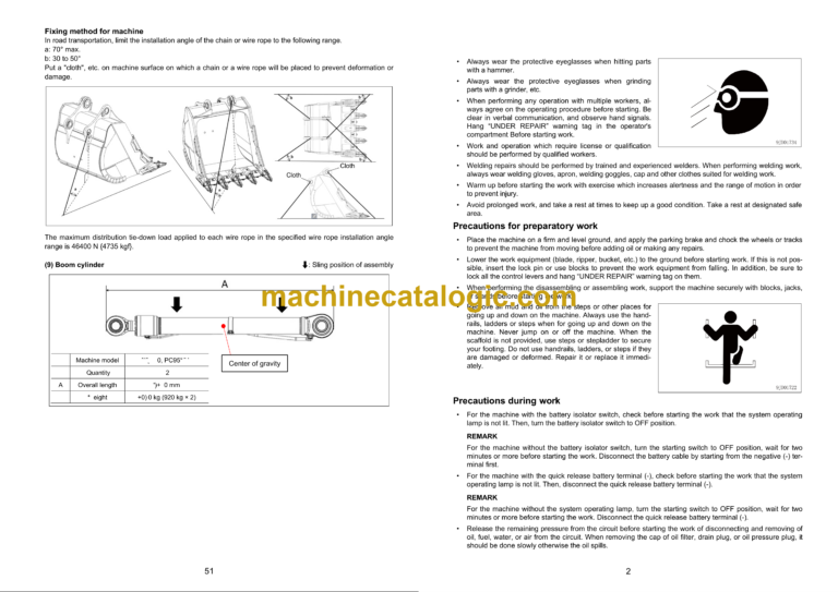
A-11
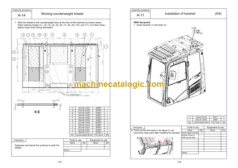
Assembly of blade
A-12
Installation of blade
A-13 Installation of Komtrax antenna
A-14 Installation of ROPS guard
A-15 Installation of platform (if equipped)
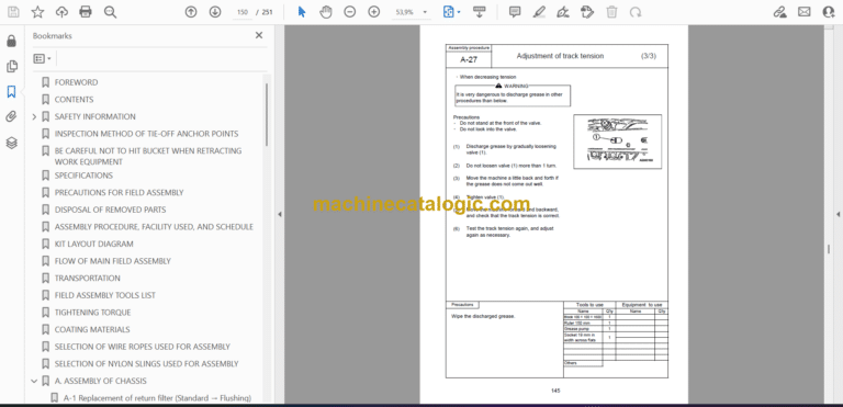
A-16 Check track tension
A-17 Check fuel, coolant and lubricants
A-18 Bleeding air from hydraulic cylinders
A-19 Lubricating
A-20 Installation of fuel quick charge piping (if equipped)
A-21 Installation of ladder pump and switches (In machine with additional ladder)
A-22 Installation of ladder (In machine with ladder)
A-23 Installation of guardrail (when ladder is not installed)
A-24 Installation of fire extinguisher bracket (if equipped)
A-25 Installation of stroke sensing blade lift cylinder (For ICT specification)
A-26 Installation of stroke sensor harness (When installing the ICT local modification kit)
A-27 Installation of IMU sensor (When installing the ICT local modification kit)
A-28 Installation of ICT harness (When installing the ICT local modification kit)
A-29 Installation of AUX BOX (For ICT specification)
A-30 Installation of navigation controller (When installing the ICT local modification kit)
A-31 Installation of control box (When installing the ICT local modification kit)
A-32 Installation of offset switch (When installing the ICT local modification kit)
M. Check and maintenance procedures after completion of assembly
M-1 Inspection of machine monitor
M-2 Setting procedure for USER ADJUST MODE
M-3 Replacement of return filter (Replacement of standard filter → special flushing parts)
M-4 Flushing of hydraulic circuit, and bleeding air from hydraulic cylinders (Part 1)
M-5 Replacement of return filter (Replacement of special flushing parts → standard filter)
M-6 Bleeding air from hydraulic cylinders (Part 2)
M-7 Method for starting up KOMTRAX terminal and default setting of KOMTRAX Plus controller
M-8 Calibration of cutting edge (For ICT specification)
Field assembly inspection report

