Komatsu PC950LC-11, PC950LC-11E0 Crawler Excavator Shop Manual (SEN06998-02)
The Komatsu PC950LC-11, PC950LC-11E0 Crawler Excavator Shop Manual (SEN06998-02) is the workshop book for doing real repairs on a large crawler excavator used in heavy earthmoving, quarry, and mining work. Techs, shop leads, and advanced trainees usually reach for this when a fault code won’t clear, a component has to come off the machine, or a rebuild is on the schedule. They’re typically trying to get from “I know the symptom” to “I know exactly which part, how to remove it, and how to put it back right.”
What this manual helps you do
- Trace hydraulic issues by following circuit descriptions and step‑by‑step test procedures for the multi‑pump hydraulic system.
- Diagnose engine, electronic, and sensor faults using the same kind of flowcharts and checks most shops rely on for this machine class.
- Follow correct disassembly and reassembly sequences for major components like travel motors, swing machinery, cylinders, and final drives.
- Check adjustment procedures for items like track tension, controls, and machine settings so you don’t create new problems while fixing one.
- Verify what special tools are normally used, where to support the machine, and common safety steps before heavy teardown work.
Who this is for
This shop manual is aimed at field technicians, dealership or fleet shop mechanics, and serious trainees working under a lead tech. Operators or managers just looking for daily checks and basic maintenance are usually better off with the Operation and Maintenance Manual instead.
FAQ
Q: Is this a PDF I can search and print?
A: Yes, this is a digital PDF you can search by keyword and print selected pages for use in the shop.
Q: Is it deep enough for full overhauls, or just basic service?
A: The Shop Manual for Komatsu PC950LC-11, PC950LC-11E0 Crawler Excavator walks through diagnostic procedures, disassembly sequences, and reference data used during workshop-level repairs. It’s meant for full repair work, not just oil changes.
Q: How do I know if it matches my exact machine version?
A: This kind of manual usually applies to specific machine variants and serial ranges, so you’ll want to match your machine ID plate against the SEN06998-02 reference before buying.
If you’re doing real troubleshooting and component‑level repair on these excavators, this is the right manual; if you only need operating tips or basic service intervals, you should keep looking for the O&M manual instead.
📘 Show Index
Komatsu PC950LC-11, PC950LC-11E0 Crawler Excavator Shop Manual (SEN06998-02) Index:
- 00 Index and Foreword
- Index
- Abbreviation List
- Foreword, Safety, Basic Information
- How to Read the Shop Manual
- Safety Notice for Operation
- Precautions to Prevent Fire
- Procedures If Fire Occurs
- Precautions When You Dispose of Waste Materials
- Engine Technology to Conform Exhaust Gas Emission
- Precautions for DEF
- General Character and Precautions for Handling
- Precautions for Adding
- Precautions for Storage
- Precautions for Fire Hazard and Leakage
- Other Precautions
- Store DEF
- Precautions When You Handle Hydraulic Equipment
- Precautions When You Disconnect and Connect Pipings
- Precautions When You Handle Electrical Equipment
- Precautions When You Handle Fuel System Equipment
- Precautions When You Handle Intake System Equipment
- Practical Use of KOMTRAX
- Disconnect and Connect Push-Pull Type Coupler
- How to Disconnect and Connect Type 1 Push-Pull Type Coupler
- How to Disconnect and Connect Type 2 Push-Pull Type Coupler
- How to Disconnect and Connect Type 3 Push-Pull Type Coupler
- Precautions for Disconnection and Connection of Connectors
- How to Disconnect and Connect Deutsch Connector
- How to Disconnect and Connect Slide Lock Type Connector
- How to Disconnect and Connect Connector with Lock to Pull
- How to Disconnect and Connect Connector with Lock to Push
- How to Disconnect and Connect Connector with Housing to Rotate
- How to Read the Codes for Electric Cable
- Explanation of Terms for Maintenance Standard
- Standard Tightening Torque Table
- Conversion Table
- 01 Specifications
- Table of Contents
- Specifications
- Specification Drawing
- Specification Drawing: PC900LC-11
- Specification Drawing: PC900LC-11(SE)
- Specification Drawing: PC950-11E0
- Specification Drawing: PC950-11E0(SE)
- Specification Drawing: PC950LC-11E0
- Specification Drawing: PC950LC-11E0(SE)
- Specification Drawing: PC950-11
- Specification Drawing: PC950-11(SE)
- Specification Drawing: PC950LC-11
- Specification Drawing: PC950LC-11(SE)
- Working Range Drawings
- Working Range Drawings: PC900LC-11
- Working Range Drawings: PC900LC-11(SE)
- Working Range Drawings: PC950-11E0
- Working Range Drawings: PC950-11E0(SE)
- Working Range Drawings: PC950LC-11E0
- Working Range Drawings: PC950LC-11E0(SE)
- Working Range Drawings: PC950-11
- Working Range Drawings: PC950-11(SE)
- Working Range Drawings: PC950LC-11
- Working Range Drawings: PC950LC-11(SE)
- Specifications
- Specifications: PC900LC-11
- Specifications: PC900LC-11(SE)
- Specifications: PC950-11E0
- Specifications: PC950-11E0(SE)
- Specifications: PC950LC-11E0
- Specifications: PC950LC-11E0(SE)
- Specifications: PC950-11
- Specifications: PC950-11(SE)
- Specifications: PC950LC-11
- Specifications: PC950LC-11(SE)
- Weight Table
- Weight Table: PC900LC-11
- Weight Table: PC900LC-11(SE)
- Weight Table: PC950-11E0
- Weight Table: PC950-11E0(SE)
- Weight Table: PC950LC-11E0
- Weight Table: PC950LC-11E0(SE)
- Weight Table: PC950-11
- Weight Table: PC950-11(SE)
- Weight Table: PC950LC-11
- Weight Table: PC950LC-11(SE)
- How to Use Fuel, Coolant and Lubricants by Ambient Temperature (PC900LC-11)
- How to Use Fuel, Coolant and Lubricants by Ambient Temperature (PC950-11, PC950LC-11, PC950-11E0, PC950LC-11E0)
- 10 Structure and Function
- Table of Contents
- Urea SCR System
- Layout Drawing of Urea SCR System
- Urea SCR System Diagram
- Function of Urea SCR System
- Function of DEF System
- Inducement Strategy
- Component Parts of Urea SCR System
- DEF Mixing Tube
- SCR Assembly
- DEF Tank
- DEF Pump
- DEF Injector
- DEF Hose
- DEF Tank Heating Valve
- Boot-up System
- Layout Drawing of Boot-up System
- System Operating Lamp System
- System Diagram of System Operating Lamp System
- Function of Operation Lamp System
- Battery Disconnect Switch
- Function of Battery Disconnect Switch
- Engine System
- Layout Drawing of Engine System
- Function of Engine System
- Engine Control System
- System Diagram of Engine Control
- Function of Engine Control System
- Auto-Deceleration System
- System Diagram of Auto-Deceleration System
- Function of Auto-Deceleration System
- Operation of Auto-Deceleration System
- Automatic Low Idle System
- Automatic Low Idle System Diagram
- Function of Automatic Low Idle System
- Operation of Automatic Low Idle System
- Engine Automatic Warm-up System
- System Diagram of Engine Automatic Warm-up System
- Function of Engine Automatic Warm-up System
- Overheat Prevention System
- Overheat Prevention System Diagram
- Function of Overheat Prevention System
- Turbocharger Protection System
- System Diagram of Turbocharger Protection System
- Function of Turbocharger Protection System
- Automatic Idle Stop System
- System Diagram of Automatic Idle Stop System
- Function of Automatic Idle Stop System
- Component Parts of Engine System
- PTO
- PTO Lubrication System
- VGT
- EGR System
- EGR Valve
- EGR Cooler
- KCCV System
- KCCV Ventilator
- KDPF
- Cooling System
- Layout Drawing of Cooling System
- Specifications of Cooling System
- Fan Speed Control System of Hydraulic Fan
- Fan Speed Control System Diagram of Hydraulic Fan
- Function of Fan Speed Control System of Hydraulic Fan
- Engine Output Control System of Hydraulic Fan
- Engine Output Control System Diagram of Hydraulic Fan
- Function of Engine Output Control System of Hydraulic Fan
- Fan Reverse Rotation System of Hydraulic Fan
- Fan Reverse Rotation System Diagram of Hydraulic Fan
- Function of Fan Reverse Rotation System of Hydraulic Fan
- Component Parts of Cooling System
- Cooling Fan Pump of Oil Cooler
- Cooling Fan Motor of Radiator
- Cooling Fan Motor of Oil Cooler
- Control System
- Layout Drawing of Control System
- Machine Monitor System
- System Diagram of Machine Monitor System
- Function of Machine Monitor System
- KomVision System
- Layout Drawing of KomVision System
- System Diagram of KomVision System
- Function of KomVision System
- KOMTRAX System
- System Diagram of KOMTRAX System
- Function of KOMTRAX System
- Component Parts of Control System
- Machine Monitor
- KomVision Controller
- KomVision Camera
- Gateway Function Controller
- Communication Terminal
- Pump Controller 1
- Pump Controller 2
- Pump Controller 3
- Resistor for Pump Secondary Drive
- CAN Terminating Resistor
- Engine Controller
- Fuel Control Dial
- Fuel Feed Pump
- Fuel Feed Pump Switch
- Hydraulic System
- Layout Drawing of Hydraulic System
- Electronic OLSS
- Structure of Electronic OLSS
- Function of Electronic OLSS
- Engine and Pump Combined Control System
- Engine and Pump Combined Control System Diagram
- Function of Engine and Pump Combined Control System
- Component Parts of Hydraulic System
- Hydraulic Tank
- Main Pump
- Control Valve
- Variable Back Pressure Valve
- Counterweight Remover System
- Work Equipment System
- Layout Drawing of Work Equipment System
- Work Equipment System Diagram
- Machine Push-up System
- Machine Push-up System Diagram
- Function of Machine Push-up System
- Boom Shockless Control Function
- Boom Shockless Control Function System Diagram
- Operation of Boom Shockless Control Function
- PPC Lock System
- System Diagram of PPC Lock
- Function of PPC Lock System
- Work Equipment and Travel Automatic Lock System
- System Diagram of Lock Lever Automatic Lock System
- Function of Work Equipment and Travel Automatic Lock System
- Operation of Lock Lever Automatic Lock System
- Attachment Oil Flow Adjuster System
- Attachment Oil Flow Adjuster System Diagram
- Layout Drawing of Attachment Oil Flow Adjuster System
- Function of Attachment Oil Flow Adjuster System
- Component Parts of Work Equipment System
- Work Equipment and Swing PPC Valve
- 1st-Line Attachment PPC Valve
- PPC Shuttle Valve
- Solenoid Valve
- Boom Anti-Drop Valve
- Arm Anti-Drop Valve
- Boom Regeneration Valve
- Lock Valve
- Quick Return Valve
- Attachment Circuit Selector Valve (For Low Pressure)
- Pilot Circuit Accumulator
- Accumulator of Quick Return Circuit
- 2ATT Valve
- Travel High Pressure Selector Valve
- Auto-Greasing System
- Layout Drawing of Auto-Greasing System
- Grease Lubrication System Diagram
- Function of Grease Lubrication System
- Specifications of Grease Lubrication System
- Component Parts of Grease Lubrication System
- Grease Pump
- Automatic Lubrication Injector
- Swing System
- Layout Drawing of Swing System
- Swing Control System Diagram
- Operation of Swing System
- Function of Swing Control System
- Function of Swing Priority and Boom Raise Priority System
- Component Parts of Swing System
- Charge Pump and Radiator Cooling Fan Pump
- Swing Pump
- Neutral Hold Valve
- Charge Relief Valve of Electronically Controlled Close Circuit Swing System
- Charge Accumulator
- Swing Motor
- Swing Machinery
- Swing Circle
- Travel System
- Layout Drawing of Travel System
- System Diagram of Travel Control System
- Function of Travel Control System
- Component Parts of Travel System
- Straight-Travel Valve
- Travel Motor (PC900LC-11)
- Travel Motor (PC950-11, PC950LC-11 ,PC950-11E0, PC950LC-11E0)
- Final Drive (PC900LC-11)
- Final Drive (PC950-11E0, PC950LC-11E0)
- Travel PPC Valve
- Center Swivel Joint
- Undercarriage and Frame
- Layout Drawing of Undercarriage
- Specifications of Undercarriage (PC900LC-11)
- Specifications of Undercarriage (PC950-11E0, PC950LC-11E0)
- Lifting System
- Hydraulically Operated Stairway System
- Layout Drawing of Hydraulically Operated Stairway System
- Hydraulically Operated Stairway System Diagram
- Function of Hydraulically Operated Stairway System
- Component Parts of Lifting System
- Switch Box
- Proximity Switch Part
- Control Valve Assembly
- Work Equipment
- Structure of Work Equipment
- Function of Work Equipment
- Work Equipment Clearance Adjustment Shim
- Function of Work Equipment Clearance Adjustment Shim
- Bucket Clearance Adjustment Shim
- Function of Bucket Clearance Adjustment Shim
- CAB Related Parts
- CAB
- CAB Mount
- Structure of CAB Mount
- Function of CAB Mount
- CAB Tipping Stopper
- Structure of CAB Tipping Stopper
- Function of CAB Tipping Stopper
- 20 Standard Value Table
- Table of Contents
- Standard Value Table for Engine
- Standard Value Table for Engine: PC900LC-11
- Standard Value Table for Engine: PC900LC-11(SE)
- Standard Value Table for Engine: PC950-11, PC950-11E0
- Standard Value Table for Engine: PC950-11E0(SE)
- Standard Value Table for Engine: PC950LC-11, PC950LC-11E0
- Standard Value Table for Engine: PC950LC-11E0(SE)
- Standard Value Table for Machine
- Standard Value Table for Machine: PC900LC-11
- Standard Value Table for Machine: PC900LC-11(SE)
- Standard Value Table for Machine: PC950-11, PC950-11E0
- Standard Value Table for Machine: PC950-11E0 (Turkish specification, Chile specification)
- Standard Value Table for Machine: PC950-11E0 (SE)
- Standard Value Table for Machine: PC950-11E0 (SE) (Turkish specification, Chile specification)
- Standard Value Table for Machine: PC950LC-11, PC950LC-11E0
- Standard Value Table for Machine: PC950LC-11E0 (Turkish Specifications)
- Standard Value Table for Machine: PC950LC-11E0 (SE)
- Standard Value Table for Machine: PC950LC-11E0 (SE) (Turkish Specifications)
- Machine Posture and Procedures to Measure Performance
- 30 Testing and Adjusting
- Table of Contents
- Precautions Before Work
- Related Information on Testing and Adjusting
- Differences In Machine Monitor Symbols
- Tools for Testing and Adjusting
- Sketch of Tools for Testing and Adjusting
- Engine and Cooling System
- Examine Engine Speed
- How to Examine Engine Speed
- Examine Boost Pressure
- How to Examine Boost Pressure on Machine Monitor
- How to Examine Boost Pressure by Testing Tool
- Examine Exhaust Gas Temperature
- How to Examine Exhaust Gas Temperature
- Examine Mass Air Flow and Temperature Sensor
- How to Examine Mass Air Flow and Temperature Sensor
- Examine Exhaust Gas Color
- How to Examine Exhaust Gas Color with the Handy Smoke Checker
- How to Examine Exhaust Gas Color with Smoke Meter
- Examine and Adjust Valve Clearance
- How to Examine Valve Clearance
- How to Adjust Valve Clearance
- Examine Compression Pressure
- How to Examine Compression Pressure
- Examine Blowby Pressure
- How to Examine Blowby Pressure
- Examine Engine Oil Pressure
- How to Examine Engine Oil Pressure on Machine Monitor
- How to Examine Engine Oil Pressure by Testing Tool
- Examine EGR Valve and VGT Oil Pressure
- How to Examine EGR Valve and VGT Oil Pressure
- Examine Fuel Pressure
- How to Examine Fuel Pressure
- Examine Fuel Return Rate and Leakage
- How to Examine Fuel Return Rate and Leakage
- Bleed Air from Fuel System
- How to Bleed Air from Fuel System
- Examine Fuel Circuit for Leakage
- How to Examine Fuel Circuit for Leakage
- Handle Cylinder Cut-out Mode Operation
- Handle No-Injection Cranking Operation
- Clean Fuel Doser
- Write Injector Compensation Value to Engine Controller
- How to Write Injector Compensation Value
- Correct Soot Accumulation Correction Value by Ash Influence
- How to Correct Soot Accumulation Correction Value by Ash Influence
- Examine SCR Related Functions
- Examine DEF Pump Raised Pressure
- Examine Injection Volume from DEF Injector
- Examine DEF Line Heater Relay 1
- Examine DEF Line Heater Relay 2
- Examine DEF Pump Heater Relay
- Examine DEF Tank Heater Valve
- Examine SCR Denitration Efficiency
- Clean DEF Tank
- Power Train
- Examine Swing Circle Bearing Clearance
- How to Examine Swing Circle Bearing Clearance
- Undercarriage and Frame
- Examine and Adjust Track Tension
- How to Examine Track Tension
- How to Adjust Track Tension
- Hydraulic System
- Release Remained Pressure in Hydraulic Circuit
- How to Release Remained Pressure in Hydraulic System
- How to Release Remained Pressure from Swing Motor Circuit
- How to Release Remained Pressure from Travel Motor Circuit
- Examine and Adjust Oil Pressure in Work Equipment, Swing, and Travel Circuits
- How to Examine Oil Pressure in Work Equipment, Swing, and Travel Circuits
- How to Adjust Oil Pressure in Work Equipment, Swing, and Travel Circuits
- Examine and Adjust Oil Pressure in Control Circuit
- How to Examine Control Circuit Oil Pressure
- How to Adjust Oil Pressure in Control Circuit
- Examine Pump EPC Solenoid Valve Outlet Pressure
- How to Examine Pump EPC Solenoid Valve Outlet Pressure
- How to Examine Pump EPC Solenoid Valve Electric Current
- Examine and Adjust Jet Sensor Differential Pressure
- How to Examine Jet Sensor Differential Pressure with Machine Monitor
- How to Examine Jet Sensor Differential Pressure by Testing Tool
- How to Adjust Jet Sensor Differential Pressure
- How to Test Jet Sensor Differential Pressure Sensor Volt
- Test and Adjust Swing Oil Pressure
- How to Test Swing Oil Pressure
- How to Adjust Swing Oil Pressure
- Bleed Air from Swing Pump
- How to Bleed Air from Swing Pump
- How to Bleed Air from Servo Valve of Swing Pump
- Test Outlet Pressure of Swing Neutral Hold Valve EPC Solenoid Valve
- How to Test Outlet Pressure of Swing Neutral Hold Valve EPC Solenoid Valve
- How to Test Swing Neutral Hold Valve EPC Solenoid Valve Current
- How to Test Swing Neutral Hold Valve Stroke Sensor
- Open Swing Junction Valve When Swing Operation Cannot be Operated
- How to Open Swing Junction Valve When Swing Operation Cannot be Operated
- Examine Outlet Pressure of Solenoid Valve
- How to Examine Outlet Pressure of Solenoid Valve
- Operating Condition of Solenoid Valve
- Examine Outlet Pressure of EPC Solenoid Valve
- How to Examine EPC Solenoid Valve Outlet Pressure
- Examine PPC Valve Outlet Pressure
- How to Examine PPC Valve Outlet Pressure
- Adjust Play of Work Equipment and Swing PPC Valves
- How to Adjust Play of Work Equipment and Swing PPC Valves
- MEASURING AND ADJUSTING QUICK COUPLER CONTROL VALVE OUTPUT PRESSURE
- Examine Travel Deviation
- How to Examine Travel Deviation
- How to Adjust Travel Deviation
- Examine Fan Speed
- How to Examine Radiator Fan Speed
- How to Examine Oil Cooler Fan Speed
- Examine Oil Pressure in Fan Pump Circuit
- How to Examine Radiator Fan Pump Circuit Oil Pressure by Machine Monitor
- How to Examine Radiator Fan Pump Circuit Oil Pressure by Testing Tool
- How to Examine Oil Cooler Fan Pump Circuit Oil Pressure by Machine Monitor
- How to Examine Oil Cooler Fan Pump Circuit Oil Pressure by Testing Tool
- Examine Fan Pump EPC Electric Current
- How to Examine Radiator Fan Pump EPC Electric Current
- How to Examine Oil Cooler Fan Pump EPC Electric Current
- Examine Fan Pump EPC Solenoid Valve Outlet Pressure
- How to Examine Radiator Fan Pump EPC Solenoid Valve Outlet Pressure
- How to Examine EPC Solenoid Valve Outlet Pressure of Oil Cooler Fan Pump
- Examine Parts Which Cause Hydraulic Drift of Work Equipment
- How to Examine Parts Which Cause Hydraulic Drift of Boom Cylinder and Bucket Cylinder
- How to Examine the Parts Which Cause Hydraulic Drift of Arm Cylinder
- How to Examine Parts that Cause Hydraulic Drift of PPC Valve
- Examine Oil Leakage
- How to Examine Oil Leakage from Boom Cylinder
- How to Examine Oil Leakage from Arm Cylinder
- How to Examine Oil Leakage from Bucket Cylinder
- How to Examine Oil Leakage from Swing Motor
- How to Examine Oil Leakage from Travel Motor
- How to Examine Oil Leakage of Swivel Joint
- How to Examine Oil Leakage from Counterweight Remover Cylinder
- Bleed Air from Hydraulic System
- How to Bleed Air from Hydraulic Circuit
- Work Equipment
- Examine and Charge Accumulator Nitrogen Gas Pressure for Attachment
- How to Examine Accumulator Nitrogen Gas Pressure for Attachment
- CAB Related Parts
- Examine CAB Tipping Stopper
- How to Examine Cab Tipping Stopper
- How to Adjust Mirrors
- Procedure to Adjust Left Front Mirror (A)
- Procedure to Adjust Regular Position of Machine Left Front Mirror (A)
- Procedure to Adjust Right Front Mirror (B)
- Procedure to Adjust Regular Position of Machine Right Front Mirror (B)
- Procedure to Adjust Right Front Mirror (C)
- Procedure to Adjust Regular Position of Machine Right Front Mirror (C)
- Automatic Lubrication System
- Examine and Adjust Automatic Lubrication System
- How to Examine Automatic Lubrication System
- How to Adjust Automatic Lubrication System
- Lifting System
- Examine and Adjust Hydraulically Operated Stairway Proximity Switch
- How to Examine Clearance of Hydraulically Operated Stairway Proximity Switch
- How to Adjust Clearance of Hydraulically Operated Stairway Proximity Switch
- Electrical System
- Set and Operate Machine Monitor
- Operator Mode
- Function to Show Technician Identification Status Screen
- Function to Show Operator Identification Input Screen
- Examine Function by LCD (Liquid Crystal Display)
- Examine Function of Service Meter
- Usage Limitation and Maintenance Password Change Function
- Service Mode
- How to Operate Service Mode
- How to See Pre-defined Monitoring Information
- How to Examine Monitoring Information
- Abnormality Record Menu
- How to See Maintenance Record
- Maintenance Mode Setting
- How to Set Phone Number Entry
- Default Menu
- Diagnostic Tests Menu
- Adjustment Menu
- Machine Configuration Menu
- No-Injection Cranking Operation
- KOMTRAX Settings Menu
- How to Show Service Message
- How to Start Up KOMTRAX System (Machine with Gateway Function Controller)
- How to Stop Use of KOMTRAX System (Machine with Gateway Function Controller)
- Adjust Rearview Camera Angle
- How to Adjust Rearview Camera Angle
- Adjust KomVision Camera Angle
- How to Adjust KomVision Camera Angle
- Adjust KomVision Related Function
- Setting of KomVision (Main Setting)
- Setting of KomVision (Camera Setting)
- Setting of KomVision (Camera Calibration)
- KomVision screen – Check 12 m visibility
- Handle Voltage Circuit of Engine Controller
- Handle Battery Disconnect Switch
- Examine Diodes
- How to Examine Diodes by Digital Tester
- How to Examine Diodes by Analog Tester
- Pm Clinic
- Pm Clinic Service
- Pm Clinic Check Sheet: PC900LC-11
- Pm Clinic Check Sheet: PC900LC-11(SE)
- Pm Clinic Check Sheet: PC950-11, PC950-11E0
- Pm Clinic Check Sheet: PC950-11E0 (Turkish specification, Chile specification)
- Pm Clinic Check Sheet: PC950-11E0 (SE)
- Pm Clinic Check Sheet: PC950-11E0 (SE) (Turkish Specifications, Chile specification)
- Pm Clinic Check Sheet: PC950LC-11, PC950LC-11E0
- Pm Clinic Check Sheet: PC950LC-11E0 (Turkish Specifications)
- Pm Clinic Check Sheet: PC950LC-11E0 (SE)
- Pm Clinic Check Sheet: PC950LC-11E0 (SE) (Turkish Specifications)
- 40 Troubleshooting
- Table of Contents
- Precautions Before Work
- Related Information to Troubleshooting
- General Troubleshooting Points
- Troubleshooting Points for Aftertreatment System
- Sequence of Events in Troubleshooting
- Checks Before Troubleshooting
- Inspection Procedure Before Troubleshooting
- Test in Accordance with Testing Procedure
- Examine Fuel Level and Type
- Examine for Impure Ingredient in Fuel
- Examine Fuel Prefilter
- Examine Water Separator, Drain Water and Sediment
- How to Examine Water Separator, Drain Water and Sediment (Machine with Large Capacity Prefilter)
- Replace Fuel Prefilter Cartridge
- How to Replace Fuel Prefilter Cartridge (Machine with Large Capacity Prefilter)
- Examine Fuel Main Filter
- Examine Water Pump for Leakage
- Examine Engine Oil Level (Oil Quantity in Oil Pan)
- Examine Coolant Level (Expansion Tank)
- How to Replace Coolant Filter Cartridge
- Examine Air Cleaner Clogging
- Clean Outer Element
- Replace Element
- Check Hydraulic Oil Level
- Examine Hydraulic Oil Strainer
- Examine Hydraulic Oil Filter
- Examine Oil Level in Swing Machinery Case
- Examine Oil Level in PTO Case
- Examine PTO Lubrication Filter Strainer
- Examine Oil Level in Final Drive Case (PC900LC-11)
- Examine Oil Level in Final Drive Case (PC950-11E0,PC950LC-11E0)
- Bleed Air from Fuel System
- Bleed Air from Hydraulic System
- How to Examine Electrical Components
- Preparation for Troubleshooting of Electrical System
- Preparation for Troubleshooting of Machine Monitor
- Preparation for Troubleshooting of Engine Controller
- Preparation for Troubleshooting of Pump Controller
- Preparation for Troubleshooting of Gateway Function Controller
- How to Disconnect and Connect Connector with a Special Lock
- Procedure for Troubleshooting
- Symptom and Troubleshooting Numbers
- Information Shown in Troubleshooting Table
- How to Diagnose Wiring Harness for Open Circuit of Pressure Sensor System
- Connectors List (PC900LC-11)
- Connector Layout (PC900LC-11) (1)
- Connector Layout (PC900LC-11) (2)
- Connector Layout (PC900LC-11) (3)
- Connector Layout (PC900LC-11) (4)
- Connector Layout (PC900LC-11) (5)
- Connector Layout (PC900LC-11) (6)
- Connector Layout (PC900LC-11) (7)
- Connector Layout (PC900LC-11) (8)
- Connector Layout (PC900LC-11) (9)
- Connector Layout (PC900LC-11) (10)
- Connector Layout (PC900LC-11) (11)
- Connector Layout (PC950-11, PC950LC-11)
- Connector Layout (PC950-11, PC950LC-11) (1)
- Connector Layout (PC950-11, PC950LC-11) (2)
- Connector Layout (PC950-11, PC950LC-11) (3)
- Connector Layout (PC950-11, PC950LC-11) (4)
- Connector Layout (PC950-11, PC950LC-11) (5)
- Connector Layout (PC950-11, PC950LC-11) (6)
- Connector Layout (PC950-11, PC950LC-11) (7)
- Connector Layout (PC950-11, PC950LC-11) (8)
- Connector Layout (PC950-11, PC950LC-11) (9)
- Connector Layout (PC950-11, PC950LC-11) (10)
- Connector Layout (PC950-11, PC950LC-11) (11)
- Connector Layout (PC950-11, PC950LC-11) (12)
- Connector List (PC950-11E0, PC950LC-11E0)
- Connector Layout (PC950-11E0, PC950LC-11E0) (1)
- Connector Layout (PC950-11E0, PC950LC-11E0) (2)
- Connector Layout (PC950-11E0, PC950LC-11E0)(3)
- Connector Layout (PC950-11E0, PC950LC-11E0) (4)
- Connector Layout (PC950-11E0, PC950LC-11E0) (5)
- Connector Layout (PC950-11E0, PC950LC-11E0) (6)
- Connector Layout (PC950-11E0, PC950LC-11E0) (7)
- Connector Layout (PC950-11E0, PC950LC-11E0) (8)
- Connector Layout (PC950-11E0, PC950LC-11E0) (9)
- Connector Layout (PC950-11E0, PC950LC-11E0) (10)
- Connector Layout (PC950-11E0, PC950LC-11E0) (11)
- Connector Layout (PC950-11E0, PC950LC-11E0) (12)
- Connector Contact Connection Table
- T-Branch Box and T-Branch Adapter Table
- Fuse Location Table
- Precautions When You Clean and Replace KDPF (KCSF and KDOC)
- Prepare Short Circuit Electrical Connector (For Failure Codes [CA1883] and [CA3135])
- Failure Code Table
- Troubleshooting by Failure Code (Display of Code)
- Failure Code [602KNX]
- Failure Code [60D2NX]
- Failure Code [6AZ0ZG]
- Failure Code [879AKA]
- Failure Code [879AKB]
- Failure Code [879BKA]
- Failure Code [879BKB]
- Failure Code [879CKA]
- Failure Code [879CKB]
- Failure Code [879DKZ]
- Failure Code [879EMC]
- Failure Code [879FMC]
- Failure Code [879GKX]
- Failure Code [8800ZG]
- Failure Code [A1U0N3]
- Failure Code [A1U0N4]
- Failure Code [A900FR]
- Failure Code [A900N6]
- Failure Code [A900NY]
- Failure Code [AA10NX]
- Failure Code [AB00KE]
- Failure Code [AQ10N3]
- Failure Code [AS00N3]
- Failure Code [AS00R2]
- Failure Code [AS00R3]
- Failure Code [AS00R4]
- Failure Code [AS00R5]
- Failure Code [AS00R6]
- Failure Code [AS00ZK]
- Failure Code [AS10KM]
- Failure Code [AS10NR]
- Failure Code [AS10NT]
- Failure Code [B@BAZG]
- Failure Code [B@BAZK]
- Failure Code [B@BCNS]
- Failure Code [B@BCQA]
- Failure Code [B@BCZK]
- Failure Code [B@HANS]
- Failure Code [CA115]
- Failure Code [CA122]
- Failure Code [CA123]
- Failure Code [CA131]
- Failure Code [CA132]
- Failure Code [CA135]
- Failure Code [CA141]
- Failure Code [CA144]
- Failure Code [CA145]
- Failure Code [CA153]
- Failure Code [CA154]
- Failure Code [CA187]
- Failure Code [CA221]
- Failure Code [CA222]
- Failure Code [CA227]
- Failure Code [CA234]
- Failure Code [CA238]
- Failure Code [CA239]
- Failure Code [CA249]
- Failure Code [CA256]
- Failure Code [CA271]
- Failure Code [CA272]
- Failure Code [CA273]
- Failure Code [CA274]
- Failure Code [CA322]
- Failure Code [CA323]
- Failure Code [CA324]
- Failure Code [CA325]
- Failure Code [CA331]
- Failure Code [CA332]
- Failure Code [CA343]
- Failure Code [CA351]
- Failure Code [CA352]
- Failure Code [CA356]
- Failure Code [CA357]
- Failure Code [CA386]
- Failure Code [CA428]
- Failure Code [CA429]
- Failure Code [CA441]
- Failure Code [CA442]
- Failure Code [CA449]
- Failure Code [CA451]
- Failure Code [CA452]
- Failure Code [CA515]
- Failure Code [CA516]
- Failure Code [CA553]
- Failure Code [CA555]
- Failure Code [CA556]
- Failure Code [CA559]
- Failure Code [CA595]
- Failure Code [CA687]
- Failure Code [CA689]
- Failure Code [CA691]
- Failure Code [CA692]
- Failure Code [CA697]
- Failure Code [CA698]
- Failure Code [CA731]
- Failure Code [CA778]
- Failure Code [CA1117]
- Failure Code [CA1664]
- Failure Code [CA1669]
- Failure Code [CA1673]
- Failure Code [CA1677]
- Failure Code [CA1678]
- Failure Code [CA1682]
- Failure Code [CA1683]
- Failure Code [CA1684]
- Failure Code [CA1686]
- Failure Code [CA1691]
- Failure Code [CA1694]
- Failure Code [CA1695]
- Failure Code [CA1696]
- Failure Code [CA1712]
- Failure Code [CA1713]
- Failure Code [CA1714]
- Failure Code [CA1715]
- Failure Code [CA1776]
- Failure Code [CA1777]
- Failure Code [CA1843]
- Failure Code [CA1844]
- Failure Code [CA1879]
- Failure Code [CA1881]
- Failure Code [CA1883] (PC900LC-11)
- Failure Code [CA1883] (PC900LC-11E0)
- Failure Code [CA1885]
- Failure Code [CA1887]
- Failure Code [CA1921]
- Failure Code [CA1922]
- Failure Code [CA1923]
- Failure Code [CA1924]
- Failure Code [CA1925]
- Failure Code [CA1927]
- Failure Code [CA1928]
- Failure Code [CA1942]
- Failure Code [CA1963]
- Failure Code [CA1977]
- Failure Code [CA1993] (PC900LC-11)
- Failure Code [CA1993] (PC900LC-11E0)
- Failure Code [CA2185]
- Failure Code [CA2186]
- Failure Code [CA2249]
- Failure Code [CA2265]
- Failure Code [CA2266]
- Failure Code [CA2271]
- Failure Code [CA2272]
- Failure Code [CA2349]
- Failure Code [CA2353]
- Failure Code [CA2357]
- Failure Code [CA2381]
- Failure Code [CA2382]
- Failure Code [CA2383]
- Failure Code [CA2386]
- Failure Code [CA2387]
- Troubleshooting Flowchart
- Failure Code [CA2555]
- Failure Code [CA2556]
- Failure Code [CA2637]
- Failure Code [CA2639]
- Failure Code [CA2732]
- Failure Code [CA2733]
- Failure Code [CA2741]
- Failure Code [CA2765]
- Failure Code [CA2771]
- Failure Code [CA2777]
- Failure Code [CA2878]
- Failure Code [CA2881]
- Failure Code [CA2976]
- Failure Code [CA3133]
- Failure Code [CA3134]
- Failure Code [CA3135]
- Failure Code [CA3142]
- Failure Code [CA3143]
- Failure Code [CA3144]
- Failure Code [CA3146]
- Failure Code [CA3147]
- Failure Code [CA3148]
- Failure Code [CA3151]
- Failure Code [CA3165]
- Failure Code [CA3167]
- Failure Code [CA3228]
- Failure Code [CA3229]
- Failure Code [CA3231]
- Failure Code [CA3232]
- Failure Code [CA3235]
- Failure Code [CA3239]
- Failure Code [CA3241]
- Failure Code [CA3242]
- Failure Code [CA3251]
- Failure Code [CA3253]
- Failure Code [CA3254]
- Failure Code [CA3255]
- Failure Code [CA3256]
- Failure Code [CA3311]
- Failure Code [CA3312]
- Failure Code [CA3313]
- Failure Code [CA3314]
- Failure Code [CA3315]
- Failure Code [CA3316]
- Failure Code [CA3317]
- Failure Code [CA3318]
- Failure Code [CA3319]
- Failure Code [CA3321]
- Failure Code [CA3322]
- Failure Code [CA3419]
- Failure Code [CA3421]
- Failure Code [CA3497]
- Failure Code [CA3498]
- Failure Code [CA3543]
- Failure Code [CA3545]
- Failure Code [CA3547]
- Failure Code [CA3558]
- Failure Code [CA3559]
- Failure Code [CA3562]
- Failure Code [CA3563]
- Failure Code [CA3567]
- Failure Code [CA3568]
- Failure Code [CA3571]
- Failure Code [CA3572]
- Failure Code [CA3574]
- Failure Code [CA3575]
- Failure Code [CA3577]
- Failure Code [CA3578]
- Failure Code [CA3582]
- Failure Code [CA3583]
- Failure Code [CA3596]
- Failure Code [CA3649]
- Failure Code [CA3681]
- Failure Code [CA3682]
- Failure Code [CA3713]
- Failure Code [CA3717]
- Failure Code [CA3718]
- Failure Code [CA3725]
- Failure Code [CA3741]
- Failure Code [CA3748]
- Failure Code [CA3751]
- Failure Code [CA3755]
- Failure Code [CA3866]
- Failure Code [CA3867]
- Failure Code [CA3868]
- Failure Code [CA3899]
- Failure Code [CA3911]
- Failure Code [CA3912]
- Failure Code [CA3932]
- Failure Code [CA3933]
- Failure Code [CA3934]
- Failure Code [CA3935]
- Failure Code [CA3936]
- Failure Code [CA4151]
- Failure Code [CA4152]
- Failure Code [CA4155]
- Failure Code [CA4156]
- Failure Code [CA4157]
- Failure Code [CA4158]
- Failure Code [CA4159]
- Failure Code [CA4161]
- Failure Code [CA4162]
- Failure Code [CA4163]
- Failure Code [CA4164]
- Failure Code [CA4165]
- Failure Code [CA4166]
- Failure Code [CA4168]
- Failure Code [CA4169]
- Failure Code [CA4171]
- Failure Code [CA4249]
- Failure Code [CA4251]
- Failure Code [CA4259]
- Failure Code [CA4261]
- Failure Code [CA4277]
- Failure Code [CA4281]
- Failure Code [CA4459]
- Failure Code [CA4461]
- Failure Code [CA4731]
- Failure Code [CA4732]
- Failure Code [CA4739]
- Failure Code [CA4768]
- Failure Code [CA4769]
- Failure Code [CA4842]
- Failure Code [CA4952]
- Failure Code [CA5115]
- Failure Code [CA5179]
- Failure Code [CA5181]
- Failure Code [CA5383]
- Failure Code [D108FS]
- Failure Code [D108KA]
- Failure Code [D108KB]
- Failure Code [D108KY]
- Failure Code [D10HKA]
- Failure Code [D10NFS]
- Failure Code [D10NKA]
- Failure Code [D10NKB]
- Failure Code [D10NKY]
- Failure Code [D110KB]
- Failure Code [D163KB]
- Failure Code [D195KA]
- Failure Code [D195KB]
- Failure Code [D19JKZ]
- Failure Code [D19UFS]
- Failure Code [D19UKA]
- Failure Code [D19UKB]
- Failure Code [D19UKY]
- Failure Code [D1ETKB]
- Failure Code [D1EYKB]
- Failure Code [D1F0KA]
- Failure Code [D1F0KB]
- Failure Code [D1F0KY]
- Failure Code [D1S1KA]
- Failure Code [D1S1KB]
- Failure Code [D5Z7KA]
- Failure Code [D1S1KY]
- Failure Code [D811MC]
- Failure Code [D862KA]
- Failure Code [D8ALKA]
- Failure Code [D8ALKB]
- Failure Code [D8AQKR]
- Failure Code [D8ARKR]
- Failure Code [D8G1KT]
- Failure Code [D8G6KT]
- Failure Code [DA20MC]
- Failure Code [DA22KK]
- Failure Code [DA22KT]
- Failure Code [DA25KP]
- Failure Code [DA26KP]
- Failure Code [DA29KQ]
- Failure Code [DA2JKT]
- Failure Code [DA2JKY]
- Failure Code [DA2LKA]
- Failure Code [DA2LKB]
- Failure Code [DA2QKR]
- Failure Code [DA2RKR]
- Failure Code [DA7AMC]
- Failure Code [DA7BKK]
- Failure Code [DA7BKT]
- Failure Code [DA7CKP]
- Failure Code [DA7DKP]
- Failure Code [DA7EKQ]
- Failure Code [DA7FKA]
- Failure Code [DA7FKB]
- Failure Code [DA7GKR]
- Failure Code [DA7HKR]
- Failure Code [DA7JKR]
- Failure Code [DAF0KM]
- Failure Code [DAF0KT]
- Failure Code [DAF0MB]
- Failure Code [DAF0MC]
- Failure Code [DAF3KK]
- Failure Code [DAF8KB]
- Failure Code [DAF9KQ]
- Failure Code [DAFGMC]
- Failure Code [DAFLKA]
- Failure Code [DAFLKB]
- Failure Code [DAFQKR]
- Failure Code [DAZ9KQ]
- Failure Code [DAZQKR]
- Failure Code [DB2QKR]
- Failure Code [DB2RKR]
- Failure Code [DBP0KM]
- Failure Code [DBP0KT]
- Failure Code [DBP5KB]
- Failure Code [DBP5KY]
- Failure Code [DBPQKR]
- Failure Code [DBZ0MC]
- Failure Code [DBZ2KK]
- Failure Code [DBZ2KT]
- Failure Code [DBZ5KP]
- Failure Code [DBZ6KP]
- Failure Code [DBZ6KP] (Counterweight remover specifications)
- Failure Code [DBZ9KQ]
- Failure Code [DBZJKR]
- Failure Code [DBZLKA]
- Failure Code [DBZLKB]
- Failure Code [DBZQKR]
- Failure Code [DBZRKR]
- Failure Code [DDNRKA]
- Failure Code [DDNRKY]
- Failure Code [DDNS00]
- Failure Code [DDPAKA]
- Failure Code [DDPFL4]
- Failure Code [DDXAL4]
- Failure Code [DFB1KZ]
- Failure Code [DFB2KZ]
- Failure Code [DFB3L8]
- Failure Code [DFB4L8]
- Failure Code [DFB5KZ]
- Failure Code [DFB6KZ]
- Failure Code [DGE5KB]
- Failure Code [DGH2KA]
- Failure Code [DGH2KB]
- Failure Code [DH25MA]
- Failure Code [DH26MA]
- Failure Code [DHA4KA]
- Failure Code [DHAAMA]
- Failure Code [DHACMA]
- Failure Code [DHF1MA]
- Failure Code [DHF2MA]
- Failure Code [DHF7L8]
- Failure Code [DHF7MA]
- Failure Code [DHF8L8]
- Failure Code [DHF8MA]
- Failure Code [DHHDMA]
- Failure Code [DHHDZG]
- Failure Code [DHHEMA]
- Failure Code [DHHFMA]
- Failure Code [DHHGL8]
- Failure Code [DHHGMA]
- Failure Code [DHPEMA]
- Failure Code [DHPFMA]
- Failure Code [DHPSMA]
- Failure Code [DHPTMA]
- Failure Code [DHPUMA]
- Failure Code [DHS3MA]
- Failure Code [DHS4MA]
- Failure Code [DHS8MA]
- Failure Code [DHS9MA]
- Failure Code [DHSAMA]
- Failure Code [DHSBMA]
- Failure Code [DHSCMA]
- Failure Code [DHSDMA]
- Failure Code [DHSFMA]
- Failure Code [DHSGMA]
- Failure Code [DHSHMA]
- Failure Code [DHSJMA]
- Failure Code [DHSVMA]
- Failure Code [DHTKMA]
- Failure Code [DHTKL8]
- Failure Code [DHTLL8]
- Failure Code [DHTLMA]
- Failure Code [DHVAL8]
- Failure Code [DHVAMA]
- Failure Code [DHVBL8]
- Failure Code [DHVBMA]
- Failure Code [DJE7MA]
- Failure Code [DJS1MA]
- Failure Code [DKK0KB]
- Failure Code [DKK0MA]
- Failure Code [DKR0MA]
- Failure Code [DKR1MA]
- Failure Code [DKR2MA]
- Failure Code [DKR2NX]
- Failure Code [DKR3MA]
- Failure Code [DKR3NX]
- Failure Code [DKR5MA]
- Failure Code [DKR6MA]
- Failure Code [DKTKMA]
- Failure Code [DKTMMA]
- Failure Code [DKTNMA]
- Failure Code [DKTPMA]
- Failure Code [DKULKA]
- Failure Code [DKULKB]
- Failure Code [DKULKY]
- Failure Code [DKV5L8]
- Failure Code [DKV5MA]
- Failure Code [DKVEL8]
- Failure Code [DKVEMA]
- Failure Code [DKVFL8]
- Failure Code [DKVFMA]
- Failure Code [DKVGL8]
- Failure Code [DKVGMA]
- Failure Code [DKVHL8]
- Failure Code [DKVHMA]
- Failure Code [DKVJL8]
- Failure Code [DKVJMA]
- Failure Code [DLM3KA]
- Failure Code [DLM3KB]
- Failure Code [DLM3MB]
- Failure Code [DLM8KA]
- Failure Code [DLM8KB]
- Failure Code [DLM8MB]
- Failure Code [DLMCLC]
- Failure Code [DLMCMA]
- Failure Code [DMU6KB]
- Failure Code [DR10KA]
- Failure Code [DR12KA]
- Failure Code [DR20KA]
- Failure Code [DR21KX]
- Failure Code [DR30KA]
- Failure Code [DR31KX]
- Failure Code [DR40KA]
- Failure Code [DUMBKA]
- Failure Code [DUMBKB]
- Failure Code [DV20KB]
- Failure Code [DW43KA]
- Failure Code [DW43KB]
- Failure Code [DW43KY]
- Failure Code [DW45KA]
- Failure Code [DW45KB]
- Failure Code [DW45KY]
- Failure Code [DW4CKA]
- Failure Code [DW4CKY]
- Failure Code [DW7BKA]
- Failure Code [DW7BKB]
- Failure Code [DW7BKY]
- Failure Code [DW7HKA]
- Failure Code [DW7HKB]
- Failure Code [DW7HKY]
- Failure Code [DW91KA]
- Failure Code [DW91KB]
- Failure Code [DW91KY]
- Failure Code [DW9DKA]
- Failure Code [DW9DKB]
- Failure Code [DW9DKY]
- Failure Code [DWA2KA]
- Failure Code [DWA2KB]
- Failure Code [DWA2KY]
- Failure Code [DWA7KA]
- Failure Code [DWA7KB]
- Failure Code [DWA7KY]
- Failure Code [DWADKA]
- Failure Code [DWADKB]
- Failure Code [DWADKY]
- Failure Code [DWK2KA]
- Failure Code [DWK2KB]
- Failure Code [DWK2KY]
- Failure Code [DWM1KA]
- Failure Code [DWM1KB]
- Failure Code [DWM1KY]
- Failure Code [DWN5KA]
- Failure Code [DWN5KB]
- Failure Code [DWNCKA]
- Failure Code [DWNCKB]
- Failure Code [DWNRKA]
- Failure Code [DWNRKB]
- Failure Code [DWNRKY]
- Failure Code [DWT1KA]
- Failure Code [DWT1KB]
- Failure Code [DWT1KY]
- Failure Code [DXAAKA]
- Failure Code [DXAAKA] (Counterweight Remover Specifications)
- Failure Code [DXAAKB]
- Failure Code [DXAAKB] (Counterweight Remover Specifications)
- Failure Code [DXABKA]
- Failure Code [DXABKB]
- Failure Code [DXACKA]
- Failure Code [DXACKB]
- Failure Code [DXACKY]
- Failure Code [DXACL8]
- Failure Code [DXADKA]
- Failure Code [DXADKB]
- Failure Code [DXADKY]
- Failure Code [DXADL8]
- Failure Code [DXAEKA]
- Failure Code [DXAEKB]
- Failure Code [DXAEKY]
- Failure Code [DXAEL8]
- Failure Code [DXAFKA]
- Failure Code [DXAFKB]
- Failure Code [DXAFKY]
- Failure Code [DXAFL8]
- Failure Code [DXAGKA]
- Failure Code [DXAGKB]
- Failure Code [DXAGKY]
- Failure Code [DXE7KA]
- Failure Code [DXE7KB]
- Failure Code [DXE7KY]
- Failure Code [DXE8KA]
- Failure Code [DXE8KB]
- Failure Code [DXE8KY]
- Failure Code [DXE9KA]
- Failure Code [DXE9KB]
- Failure Code [DXE9KY]
- Failure Code [DXEAKA]
- Failure Code [DXEAKB]
- Failure Code [DXEAKY]
- Failure Code [DXP1KA]
- Failure Code [DXP1KB]
- Failure Code [DXP1KY]
- Failure Code [DXP1L8]
- Failure Code [DXP2KA]
- Failure Code [DXP2KB]
- Failure Code [DXP2KY]
- Failure Code [DXP2L8]
- Failure Code [DXR3KA]
- Failure Code [DXR3KB]
- Failure Code [DXR3KY]
- Failure Code [DXR4KA]
- Failure Code [DXR4KB]
- Failure Code [DXR4KY]
- Failure Code [DXR6KA]
- Failure Code [DXR6KB]
- Failure Code [DXR6KY]
- Failure Code [DXR9KA]
- Failure Code [DXR9KB]
- Failure Code [DXR9KY]
- Failure Code [DXRCKA]
- Failure Code [DXRCKB]
- Failure Code [DXRCKY]
- Failure Code [DXRFKA]
- Failure Code [DXRFKB]
- Failure Code [DXRFKY]
- Failure Code [DXRGKA]
- Failure Code [DXRGKB]
- Failure Code [DXRGKY]
- Failure Code [DXRJKA]
- Failure Code [DXRJKB]
- Failure Code [DXRJKY]
- Failure Code [DXRKKA]
- Failure Code [DXRKKB]
- Failure Code [DXRKKY]
- Failure Code [DY20KA]
- Failure Code [DY20MA]
- Failure Code [DY2CKA]
- Failure Code [DY2CKB]
- Failure Code [DY2DKB]
- Failure Code [DY2EKB]
- Failure Code [DY2FMA]
- Failure Code [DY2GKM]
- Failure Code [DY2MMA]
- Failure Code [F311KA]
- Failure Code [F311KB]
- Failure Code [F312KA]
- Failure Code [F312KB]
- Failure Code [F313KA]
- Failure Code [F313KB]
- Failure Code [F314KA]
- Failure Code [F314KB]
- Failure Code [F315KB]
- Failure Code [F315KY]
- Failure Code [F316KB]
- Failure Code [F316KY]
- Failure Code [F318KB]
- Failure Code [F318KY]
- Failure Code [F31AKB]
- Failure Code [F31AKY]
- Failure Code [F31BKB]
- Failure Code [F31BKY]
- Failure Code [F31CKB]
- Failure Code [F31CKY]
- Failure Code [F31DKB]
- Failure Code [F31DKY]
- Failure Code [F31EKB]
- Failure Code [F31EKY]
- Failure Code [K100N1]
- Failure Code [LA10ZL]
- Failure Code [LA20ZL]
- Troubleshooting of Electrical System (E-Mode)
- Engine Does Not Start (Engine Does Not Crank)
- Manual Preheating System Does Not Operate
- Automatic Preheating System Does Not Operate
- While Preheating is in Operation, Preheating Monitor Does Not Come On
- When Starting Switch is Turned to ON Position, Machine Monitor Shows Nothing
- While Starting Switch is Turned to ON Position (with Engine Stopped), Engine Oil Level Caution Lamp Comes On in Yellow
- While Starting Switch is Turned to ON Position (with Engine Stopped), Radiator Coolant Level Caution Lamp Comes On in Yellow
- Engine Coolant Temperature Monitor Comes On in White While Engine is in Operation
- Hydraulic Oil Temperature Monitor Comes On in White While Engine is in Operation
- Air Cleaner Clogging Monitor Comes On in Yellow While Engine is in Operation
- Charge Level Monitor Comes On in Red While Engine is in Operation
- Fuel Level Monitor Comes On in Red While Engine is in Operation
- Engine Coolant Temperature Monitor Comes On in Red While Engine is in Operation
- Engine Oil Pressure Monitor Comes On in Red While Engine is in Operation
- Hydraulic Oil Temperature Monitor Comes On in Red While Engine is in Operation
- Fuel Gauge Does Not Move from Minimum or Maximum
- Display of Fuel Gauge is Different from Actual Fuel Level
- Coolant Temperature Gauge Display Does Not Move from Minimum or Maximum
- Display of Coolant Temperature Gauge is Different from Actual Coolant Temperature
- Hydraulic Oil Temperature Gauge Does Not Move from Minimum or Maximum
- Display of Hydraulic Oil Temperature Gauge is Different from Actual Oil Temperature
- Some Areas of Machine Monitor Screen are Not Shown
- Function Switch Does Not Operate
- Automatic Warm-up System Does Not Operate (in Cold Weather)
- Auto-Deceleration Monitor Does Not Come On or Go Out While Auto-Deceleration Switch is Operated
- Auto-Deceleration is Not Operated or Canceled with Lever
- Work Mode Selector Screen is Not Shown While Work Mode Switch is Operated
- When Working Mode is Changed, Setting of Engine and Hydraulic Pump is Not Changed
- Travel Speed Monitor Does Not Change While Travel Speed Switch is Operated
- Travel Speed Does Not Change Even When You Change Travel Speed
- Alarm Buzzer Does Not Stop
- Service Meter is Not Shown While Starting Switch is in OFF Position
- Service Mode Cannot be Selected
- All Work Equipment, Swing, Travel Do Not Operate
- All Work Equipment, Swing and Travel Do Not Operate (Counterweight remover specification)
- All Work Equipment, Swing, Travel Cannot be Locked
- All of Work Equipment, Swing, and Travel Mechanism Do Not Lock (Counterweight remover specification)
- Machine Does Not Swing While Swing Parking Brake Release Switch is Set to Release Position
- While Swing Parking Brake Release Switch is Turned on, Swing Brake is Not Operated
- Alarm Does Not Sound During Travel
- Travel Alarm Does Not Stop When Machine Stops
- Horn Does Not Sound
- Horn Does Not Stop
- Wiper Monitor Does Not Come On or Go Off While Wiper Switch is Operated
- Wiper Does Not Operate When Wiper Switch is Operated
- When Window Washer Switch is Operated, Window Washer Does Not Operate
- Fuel Feed Pump Does Not Operate or Stop Automatically
- "Boom RAISE" is Not Shown Correctly with Monitoring Function
- "Boom LOWER" is Not Shown Correctly with Monitoring Function
- "Arm OUT" is Not Shown Correctly with Monitoring Function
- "Arm IN" is Not Shown Correctly with Monitoring Function
- Bucket DUMP is Not Shown Correctly with Monitoring Function
- Bucket CURL is Not Shown Correctly with Monitoring Function
- Swing is Not Shown Correctly with Monitoring Function
- "Right Travel" is Not Shown Correctly with Monitoring Function
- "Left Travel" is Not Shown Correctly with Monitoring Function
- Service is Not Shown Correctly with Monitoring Function
- KOMTRAX System Does Not Operate Correctly
- Machine Push-up Function Cannot be Canceled
- Machine Push-up Function Does Not Operate
- Step Light Does Not Come on
- Step Light Does Not Go out
- Boom Shockless Function Cannot be Canceled
- Boom Shockless Function Does Not Work
- Electric Grease Gun Does Not Work
- Electric Grease Gun Does Not Stop
- Screen Shows that Emergency Stop Button is Operated
- Alarm Buzzer Does Not Operate (Quick Coupler Cylinder Extends and Retracts)
- Quick Coupler Cylinder Does Not Extend
- Quick Coupler Cylinder Does Not Retract
- Troubleshooting for Hydraulic and Mechanical Systems (H Mode)
- All Work Equipment or Travel Does Not Operate
- All Work Equipment and Travel Speeds are Low or Power is Low
- Engine Speed Drops Largely or Engine Stops
- Unusual Noise is Heard from Around Work Equipment Pump and Swing Pump
- Boom RAISE Speed or Power is Low
- Boom LOWER Speed or Power is Low
- Boom LOWER Speed or Power is Low in Machine Push Up Mode
- Arm Speed or Power is Low
- Bucket Speed or Power is Low
- Boom Does Not Operate
- Arm Does Not Operate
- Bucket Does Not Operate
- Hydraulic Drift of Boom is Large
- Hydraulic Drift of Arm is Large
- Hydraulic Drift of Bucket is Large
- Time Lag of Boom is Large
- Time Lag of Arm is Large
- Time Lag of Bucket is Large
- Machine Unintentionally Turns to One Side When Machine Travels
- Travel Deviation is Large at Start of Travel Only When Travel Lever is Fully Moved
- Regardless of the Stroke of the Travel Lever, Travel Deviation is Large at Start of Traveling
- Travel Deviation is Large at Combined Operation
- Travel Speed or Power is Low
- Only the One Side Track Can Operate (Machine Does Not Travel Forward or Reverse)
- Only the One Side Track Can Operate (Machine Can Travel Only Forward or Reverse)
- Travel Speed Does Not Change
- Upper Structure Does Not Swing to Right or Left
- Machine Swings Only in One Direction
- Swing Acceleration or Swing Speed is Low in Lateral Directions (Right and Left)
- Swing Acceleration Performance is Unsatisfactory or Swing Speed is Slow in Only One Direction
- Upper Structure Overruns Too Much When It Stops Swing Operation (Right and Left)
- Upper Structure Speed is High When It Stops Swing Operation (on One Side)
- Shock is Large When Upper Structure Stops Swing Operation (Right and Left)
- Shock is Large When Upper Structure Starts and Stops Swing Operation
- Unusual Noise is Heard from Around Swing Pump or Motor
- Large Unusual Noise is Heard When Upper Structure Stops Swing Operation in Only One Direction
- Swing Drift of Swing is Large
- Fan Rotation is Abnormal (Such as Excessive Noise or Vibration of Fan, or Overheating).
- Attachment Circuit Cannot be Changed
- Oil Flow in Attachment Circuit Cannot be Changed
- Quick Coupler Cylinder Extends and Retracts Slowly
- Troubleshooting of Engine (S-Mode)
- Information Shown in Troubleshooting Table (S-Mode)
- S-1 Engine Does Not Crank When Starting Switch is Turned to Start Position
- S-2 Engine Cranks but No Exhaust Smoke Comes Out
- S-3 Fuel is Injected but Engine Does Not Start (Misfiring: Engine Cranks but Does Not Start)
- S-4 Engine Startability is Unsatisfactory
- S-5 Engine Does Not Pick Up Smoothly
- S-6 Engine Stops During Operation
- S-7 Engine Runs Rough or is Not Stable
- S-8 Engine Lacks Power
- S-9 KDPF Becomes Clogged in a Short Time
- S-10 Engine Oil Consumption is Excessive
- S-11 Oil Becomes Dirty Quickly
- S-12 Fuel Consumption is Excessive
- S-13 Oil is in Coolant (or Coolant Spurts Back or Coolant Level goes Down)
- S-14 Oil Pressure Drops
- S-15 Fuel Mixes Into Engine Oil
- S-16 Water Mixes Into Engine Oil (Milky)
- S-17 Coolant Temperature Increases Too High (Overheating)
- S-18 Unusual Noise is Heard
- S-19 Vibration is Excessive
- S-20 Air Cannot be Bled from Fuel Circuit
- S-21 Active Regeneration is Done Frequently
- S-22 Active Regeneration Continues Long
- S-23 White Smoke is Exhausted During Active Regeneration
- S-24 DEF Consumption is Excessive
- S-25 There is Unusual Smell (Irritating Odor)
- S-26 Foreign Materials Enter DEF (DEF Increases)
- 50 Disassembly and Assembly
- Table of Contents
- Precautions Before Work
- Related Information on Disassembly and Assembly
- How to Read This Manual
- Coating Materials List
- Special Tool List
- Sketches of Special Tools
- Prepare
- Drain and Add Coolant
- How to Drain Coolant
- How to Add Coolant
- Drain and Add Hydraulic Oil
- How to Drain Hydraulic Oil
- How to Add Hydraulic Oil
- Drain and Add Fuel
- How to Drain Fuel
- How to Add Fuel
- Collect and Refill Refrigerant
- How to Collect Refrigerant
- How to Refill Refrigerant
- Engine and Cooling System
- Remove and Install Supply Pump Assembly
- How to Remove Supply Pump Assembly
- How to Install Supply Pump Assembly
- Remove and Install Injector Assembly
- How to Remove Injector Assembly
- How to Install Injector Assembly
- Remove and Install Fuel Doser Assembly
- How to Remove Fuel Doser Assembly
- How to Install Fuel Doser Assembly
- Remove and Install Cylinder Head Assembly
- How to Remove Cylinder Head Assembly
- How to Install Cylinder Head Assembly
- Remove and Install EGR Valve Assembly
- How to Remove EGR Valve Assembly
- How to Install EGR Valve Assembly
- Remove and Install EGR Cooler Assembly
- How to Remove EGR Cooler Assembly
- Install EGR Cooler Assembly
- Remove and Install Starter Assembly
- How to Remove Starting Motor Assembly
- How to Install Starting Motor Assembly
- Remove and Install Alternator Belt
- How to Remove Alternator Belt
- How to Install Alternator Belt
- Remove and Install Radiator Assembly
- How to Remove Radiator Assembly
- How to Install Radiator Assembly
- Remove and Install Hydraulic Oil Cooler Assembly
- How to Remove Hydraulic Oil Cooler Assembly
- How to Install Hydraulic Oil Cooler Assembly
- Remove and Install Aftercooler Assembly
- How to Remove Aftercooler Assembly
- How to Install Aftercooler Assembly
- Remove and Install Cooler Assembly
- How to Remove Cooling Assembly
- How to Install Cooling Assembly
- Remove and Install Cooling Fan Motor Assembly
- How to Remove Cooling Fan Motor Assembly
- How to Install Cooling Fan Motor Assembly
- Remove and Install Engine, PTO, and Hydraulic Pump Assembly
- How to Remove Engine, PTO, and Hydraulic Pump Assembly
- How to Install Engine, PTO, and Hydraulic Pump Assembly
- Remove and Install Engine Front Oil Seal
- How to Remove Engine Front Oil Seal
- How to Install Engine Front Oil Seal
- Remove and Install Engine Rear Oil Seal
- How to Remove Engine Rear Oil Seal
- How to Install Engine Rear Oil Seal
- Remove and Install Engine Hood Assembly
- How to Remove Engine Hood Assembly
- How to Install Engine Hood Assembly
- Remove and Install Fuel Tank Assembly
- How to Remove Fuel Tank Assembly
- How to Install Fuel Tank Assembly
- Remove and Install DEF Tank Assembly
- How to Remove DEF Tank Assembly
- How to Install DEF Tank Assembly
- Remove and Install DEF Tank Sensor Flange Assembly
- How to Remove DEF Tank Sensor Flange Assembly
- How to Install DEF Tank Sensor Flange Assembly
- Remove and Install DEF Tank Sensor
- How to Remove DEF Tank Sensor
- How to Install DEF Tank Sensor
- Remove and Install DEF Tank Strainer
- How to Remove DEF Tank Strainer
- How to Install DEF Tank Strainer
- Remove and Install DEF Tank Filler Port Filter
- How to Remove DEF Tank Filler Port Filter
- How to Install DEF Tank Filler Port Filter
- Remove and Install KDPF Assembly
- How to Remove KDPF Assembly
- How to Install KDPF Assembly
- Disassemble and Assemble KDPF Assembly
- How to Disassemble KDPF Assembly
- How to Assemble KDPF Assembly
- Remove and Install SCR Assembly
- How to Remove SCR Assembly
- How to Install SCR Assembly
- Remove and Install KDPF and SCR Assembly
- How to Remove KDPF and SCR Assembly
- How to Install KDPF and SCR Assembly
- Remove and Install Bellows Pipe Assembly
- How to Remove Bellows Pipe Assembly
- How to Install Bellows Pipe Assembly
- Remove and Install KCCV Assembly
- How to Remove KCCV Assembly
- How to Install KCCV Assembly
- Remove and Install DEF Mixing Tube
- How to Remove DEF Mixing Tube
- How to Install DEF Mixing Tube
- Remove and Install DEF Injector
- How to Remove DEF Injector
- How to Install DEF Injector
- Remove and Install DEF Pump
- How to Remove DEF Pump
- How to Install DEF Pump
- Remove and Install DEF Hose
- How to Remove DEF Hose
- How to Install DEF Hose
- Remove and Install Air Cleaner Assembly
- How to Remove Air Cleaner Assembly
- How to Install Air Cleaner Assembly
- Remove and Install Air Conditioner Compressor Assembly
- How to Remove Air Conditioner Compressor Assembly
- How to Install Air Conditioner Compressor Assembly
- Remove and Install Air Conditioner Condenser Assembly
- How to Remove Air Conditioner Condenser Assembly
- How to Install Air Conditioner Condenser Assembly
- Power Train
- Remove and Install PTO Assembly
- How to Remove PTO Assembly
- How to Install PTO Assembly
- Disassemble and Assemble PTO Assembly
- How to Disassemble PTO Assembly
- How to Assemble PTO Assembly
- Remove and Install Travel Motor and Final Drive Assembly
- How to Remove Travel Motor and Final Drive Assembly
- How to Install Travel Motor and Final Drive Assembly
- Disassemble and Assemble Final Drive Assembly (PC900LC-11)
- How to Disassemble Final Drive Assembly (PC900LC-11)
- How to Assemble Final Drive Assembly (PC900LC-11)
- Disassemble and Assemble Final Drive Assembly (PC950-11E0, PC950LC-11E0)
- How to Disassemble Final Drive Assembly (PC950-11E0, PC950LC-11E0)
- How to Assemble Final Drive Assembly (PC950-11E0, PC950LC-11E0)
- Remove and Install Swing Motor and Swing Machinery Assembly
- How to Remove Swing Motor and Swing Machinery Assembly
- How to Install Swing Motor and Swing Machinery Assembly
- Disassemble and Assemble Swing Machinery Assembly
- How to Disassemble Swing Machinery Assembly
- How to Assemble Swing Machinery Assembly
- Remove and Install Swing Circle Assembly
- How to Remove Swing Circle Assembly
- How to Install Swing Circle Assembly
- Undercarriage and Frame
- Disassemble and Assemble One Track Link Assembly in Field
- Disassemble One Track Link Assembly in Field
- Assemble One Track Link Assembly in Field
- Separate and Connect Track Assembly
- Separate Track Assembly
- How to Install Track Assembly
- Remove and Install Idler Assembly (PC900LC-11)
- How to Remove Idler Assembly (PC900LC-11)
- How to Install Idler Assembly (PC900LC-11)
- Remove and Install Idler Assembly (PC950-11E0, PC950LC-11E0)
- How to Remove Idler Assembly (PC950-11E0, PC950LC-11E0)
- How to Install Idler Assembly (PC950-11E0, PC950LC-11E0)
- Remove and Install Idler Cushion Assembly
- How to Remove Idler Cushion Assembly
- How to Install Idler Cushion Assembly
- Disassemble and Assemble Idler Assembly (PC900LC-11)
- How to Disassemble Idler Assembly (PC900LC-11)
- How to Assemble Idler Assembly (PC900LC-11)
- Disassemble and Assemble Idler Assembly (PC950-11E0, PC950LC-11E0)
- How to Disassemble Idler Assembly (PC950-11E0, PC950LC-11E0)
- How to Assemble Idler Assembly (PC950-11E0, PC950LC-11E0)
- Disassemble and Assemble Idler Cushion Assembly
- How to Disassemble Idler Cushion Assembly
- Assemble Idler Cushion Assembly
- Remove and Install Track Roller Assembly (PC900LC-11)
- How to Remove Track Roller Assembly (PC900LC-11)
- How to Install Track Roller Assembly (PC900LC-11)
- Remove and Install Track Roller Assembly (PC950-11E0, PC950LC-11E0)
- How to Remove Track Roller Assembly (PC950-11E0, PC950LC-11E0)
- How to Install Track Roller Assembly (PC950-11E0, PC950LC-11E0)
- Remove and Install Carrier Roller Assembly
- How to Remove Carrier Roller Assembly
- How to Install Carrier Roller Assembly
- Disassemble and Assemble Track Roller Assembly (PC900LC-11)
- How to Disassemble Track Roller Assembly (PC900LC-11)
- How to Assemble Track Roller Assembly (PC900LC-11)
- Disassemble and Assemble Track Roller Assembly (PC950-11E0, PC950LC-11E0)
- How to Disassemble Track Roller Assembly (PC950-11E0, PC950LC-11E0)
- How to Assemble Track Roller Assembly (PC950-11E0, PC950LC-11E0)
- Disassemble and Assemble Carrier Roller Assembly (PC900LC-11)
- Disassemble Carrier Roller Assembly (PC900LC-11)
- How to Assemble Carrier Roller Assembly (PC900LC-11)
- Disassemble and Assemble Carrier Roller Assembly (PC950-11E0, PC950LC-11E0)
- How to Disassemble Carrier Roller Assembly (PC950-11E0, PC950LC-11E0)
- How to Assemble Carrier Roller Assembly (PC950-11E0, PC950LC-11E0)
- Remove and Install Revolving Frame Assembly
- How to Remove Revolving Frame Assembly
- How to Install Revolving Frame Assembly
- Remove and Install Counterweight Assembly
- How to Remove Counterweight Assembly
- How to Install Counterweight Assembly
- Remove and Install Counterweight Remove Cylinder Assembly
- How to Remove Counterweight Remover Cylinder Assembly
- How to Install Counterweight Remover Cylinder Assembly
- Hydraulic System
- Remove and Install Center Swivel Joint Assembly
- How to Remove Center Swivel Joint Assembly
- Install Center Swivel Joint Assembly
- Disassemble and Assemble Center Swivel Joint Assembly
- How to Disassemble Center Swivel Joint Assembly
- How to Assemble Center Swivel Joint Assembly
- Remove and Install Hydraulic Tank Assembly
- How to Remove Hydraulic Tank Assembly
- How to Install Hydraulic Tank Assembly
- Remove and Install Hydraulic Pump Assembly
- How to Remove Hydraulic Pump Assembly
- How to Install Hydraulic Pump Assembly
- Remove and Install Control Valve Assembly
- How to Remove Control Valve Assembly
- How to Install Control Valve Assembly
- Remove and Install Neutral Hold Valve Assembly
- How to Remove Neutral Hold Valve Assembly
- How to Install Neutral Hold Valve Assembly
- Remove and Install Swing Motor Assembly
- How to Remove Swing Motor Assembly
- How to Install Swing Motor Assembly
- Disassemble and Assemble Work Equipment PPC Valve Assembly
- How to Disassemble Work Equipment PPC Valve Assembly
- How to Assemble Work Equipment PPC Valve Assembly
- Disassemble and Assemble Travel PPC Valve Assembly
- How to Disassemble Travel PPC Valve Assembly
- How to Assemble Travel PPC Valve Assembly
- Disassemble and Assemble Grease Gun Assembly
- How to Disassemble Grease Gun Assembly
- How to Assemble Grease Gun Assembly
- Work Equipment
- Remove and Install Boom Anti-drop Valve Assembly
- How to Remove Boom Anti-drop Valve Assembly
- How to Install Boom Anti-drop Valve Assembly
- Remove and Install Arm Anti-Drop Valve Assembly
- How to Remove Arm Anti-Drop Valve Assembly
- How to Install Arm Anti-Drop Valve Assembly
- Disassemble and Assemble Arm Anti-Drop Valve Assembly
- How to Disassemble Arm Anti-drop Valve Assembly
- How to Assemble Arm Anti-drop Valve Assembly
- Remove and Install Bucket Cylinder Assembly
- How to Remove Bucket Cylinder Assembly
- How to Install Bucket Cylinder Assembly
- Remove and Install Arm Cylinder Assembly
- How to Remove Arm Cylinder Assembly
- How to Install Arm Cylinder Assembly
- Remove and Install Boom Cylinder Assembly
- How to Remove Boom Cylinder Assembly
- How to Install Boom Cylinder Assembly
- Remove and Install Bucket Assembly
- How to Remove Bucket Assembly
- How to Install Bucket Assembly
- Remove and Install Arm Assembly
- How to Remove Arm Assembly
- How to Install Arm Assembly
- Remove and Install Boom Assembly
- How to Remove Boom Assembly
- How to Install Boom Assembly
- Disassemble and Assemble Counterweight Remover Cylinder Assembly
- How to Disassemble and Assemble Counterweight Remover Cylinder Assembly
- How to Assemble Counterweight Remover Cylinder Assembly
- Disassemble and Assemble Boom Cylinder Assembly
- How to Disassemble Boom Cylinder Assembly
- How to Assemble Boom Cylinder Assembly
- Disassemble and Assemble Bucket Cylinder Assembly
- How to Disassemble Bucket Cylinder Assembly
- How to Assemble Bucket Cylinder Assembly
- Disassemble and Assemble Arm Cylinder Assembly
- How to Disassemble Arm Cylinder Assembly
- How to Assemble Arm Cylinder Assembly
- CAB Related Parts
- Remove and Install Operator Cab Assembly
- How to Remove Operator Cab Assembly
- How to Install Operator Cab Assembly
- Remove and Install Operator Cab Glass (Adhered Glass)
- How to Remove Operator CAB Glass (Adhered Glass)
- How to Install Operator Cab Glass (Adhered Glass)
- Remove and Install Front Window Assembly
- Remove Front Window Assembly
- Install Front Window Assembly
- Remove and Install Floor Frame Assembly
- How to Remove Floor Frame Assembly
- How to Install Floor Frame Assembly
- Remove and Install Air Conditioner Unit Assembly
- How to Remove Air Conditioner Unit Assembly
- How to Install Air Conditioner Unit Assembly
- Remove and Install Operator Seat
- How to Remove Operator Seat
- How to Install Operator Seat
- How to Remove and Install Seat Belt
- How to Remove Seat Belt
- How to Install Seatbelt
- Remove and Install Front Wiper Assembly
- Remove Front Wiper Assembly
- How to Install Front Wiper Assembly
- Electrical System
- Remove and Install Engine Controller Assembly
- How to Remove Engine Controller Assembly
- How to Install Engine Controller Assembly
- Remove and Install Pump Controller1 Assembly
- How to Remove Pump Controller1 Assembly
- How to Install Pump Controller1 Assembly
- Remove and Install Pump Controller2 Assembly
- How to Remove Pump Controller2 Assembly
- How to Install Pump Controller2 Assembly
- Remove and Install Pump Controller3 Assembly
- How to Remove Pump Controller3 Assembly
- How to Install Pump Controller3 Assembly
- Remove and Install KomVision Controller Assembly
- Remove KomVision Controller Assembly
- Install KomVision Controller Assembly
- Remove and Install Machine Monitor Assembly
- How to Remove Machine Monitor Assembly
- How to Install Machine Monitor Assembly
- Remove and Install Mass Air Flow and Temperature Sensor
- How to Remove Mass Air Flow and Temperature Sensor
- How to Install Mass Air Flow and Temperature Sensor
- Remove and Install KCCV Crankcase Pressure Sensor
- How to Remove KCCV Crankcase Pressure Sensor
- How to Install KCCV Crankcase Pressure Sensor
- Remove and Install KDPF Temperature Sensor
- How to Remove KDPF Temperature Sensor
- How to Install KDPF Temperature Sensor
- Remove and Install KDPF Differential Pressure Sensor
- How to Remove KDPF Differential Pressure Sensor
- How to Install KDPF Differential Pressure Sensor
- Remove and Install SCR Temperature Sensor
- How to Remove SCR Temperature Sensor
- How to Install SCR Temperature Sensor
- Remove and Install Ammonia Sensor
- How to Remove Ammonia Sensor
- How to Install Ammonia Sensor
- Remove and Install SCR Outlet NOx Sensor
- How to Remove SCR Outlet NOx Sensor
- How to Install SCR Outlet NOx Sensor
- Remove and Install KomVision Camera
- How to Remove KomVision Camera
- How to Install KomVision Camera
- Remove and Install Gateway Function Controller Assembly
- How to Remove Gateway Function Controller Assembly
- How to Install Gateway Function Controller Assembly
- 60 Maintenance Standard
- Table of Contents
- Engine and Cooling System
- Maintenance Standard for Engine Mount
- Maintenance Standard for PTO
- Maintenance Standard for Cooling System
- Maintenance Standard of Cooling Fan Pump of Oil Cooler
- Maintenance Standard for Servo Valve
- Maintenance Standard of Cooling Fan Motor of Radiator
- Maintenance Standard of Cooling Fan Motor of Oil Cooler
- Power Train
- Maintenance Standard for Swing Circle
- Maintenance Standard for Swing Machinery
- Maintenance Standard for Final Drive (PC900LC-11)
- Maintenance Standard for Final Drive (PC950-11, PC950LC-11, PC950-11E0, PC950LC-11E0)
- Maintenance Standard for Sprocket (PC900LC-11)
- Maintenance Standard for Sprocket (PC950-11, PC950LC-11, PC950-11E0, PC950LC-11E0)
- Maintenance Standard for Sprocket Tooth Profile Full-Scale Drawing (PC900LC-11)
- Maintenance Standard for Sprocket Tooth Profile Full-Scale Drawing (PC950-11, PC950LC-11, PC950-11E0, PC950LC-11E0)
- Undercarriage and Frame
- Maintenance Standard of Track Frame and Idler Cushion (PC900LC-11)
- Maintenance Standard of Track Frame and Idler Cushion (PC950-11, PC950LC-11, PC950-11E0, PC950LC-11E0)
- Maintenance Standard for Idler (PC900LC-11)
- Maintenance Standard for Idler (PC950-11, PC950LC-11, PC950-11E0, PC950LC-11E0)
- Maintenance Standard for Track Roller (PC900LC-11)
- Maintenance Standard for Track Roller (PC950-11, PC950LC-11, PC950-11E0, PC950LC-11E0)
- Maintenance Standard for Carrier Roller (PC900LC-11)
- Maintenance Standard for Carrier Roller (PC950-11, PC950LC-11, PC950-11E0, PC950LC-11E0)
- Maintenance Standard for Track Shoes (PC900LC-11)
- Maintenance Standard for Track Shoes (PC950-11, PC950LC-11, PC950-11E0, PC950LC-11E0)
- Maintenance Standard for Double Shoes (PC900LC-11)
- Maintenance Standard for Double Shoes (PC950-11, PC950LC-11, PC950-11E0, PC950LC-11E0)
- Hydraulic System
- Maintenance Standard for Main Pump
- Maintenance Standard for Main Pump Servo Valve
- Maintenance Standard for Main Pump EPC Valve
- Maintenance Standard of Swing Pump
- Maintenance Standard of EPC Valve of Swing Pump
- Maintenance Standard of Neutral Hold Valve
- Maintenance Standard of EPC Valve of Neutral Hold Valve
- Maintenance Standard of Charge Pump and Radiator Cooling Fan Pump
- Maintenance Standard for Swing Motor
- Maintenance Standard for Swing Junction Valve
- Maintenance Standard for Travel Motor (PC900LC-11)
- Maintenance Standard for Travel Motor (PC950-11, PC950LC-11, PC950-11E0, PC950LC-11E0)
- Maintenance Standard for Control Valve
- Maintenance Standard for Variable Back Pressure Valve
- Maintenance Standard for Counterweight Remover Cylinder
- Maintenance Standard of Boom Regeneration Valve
- Maintenance Standard of Lock Valve (Common to Boom Lock Valve and Arm Lock Valve)
- Maintenance Standard of Quick Return Valve
- Maintenance Standard for Work Equipment and Swing PPC Valve
- Maintenance Standard for Travel PPC Valve
- Maintenance Standard for 1st-Line Attachment PPC Valve
- Maintenance Standard for Solenoid Valve
- Maintenance Standard for Attachment Circuit Selector Valve
- Maintenance Standard for Center Swivel Joint
- Maintenance Standard for Arm Anti-Drop Valve
- Work Equipment
- Maintenance Standard for Work Equipment Linkage
- Dimensions of Arm (PC900LC-11)
- Dimensions of Arm (PC950-11, PC950LC-11, PC950-11E0, PC950LC-11E0)
- Dimensions of Arm (PC900LC-11, PC950-11, PC950LC-11, PC950-11E0, PC950LC-11E0)(SE)
- Dimensions of Bucket (PC900LC-11)
- Dimensions of Bucket (PC950-11, PC950LC-11, PC950-11E0, PC950LC-11E0)
- Dimensions of Bucket (PC900LC-11, PC950-11, PC950LC-11, PC950-11E0, PC950LC-11E0)(SE)
- Maintenance Standard for Boom Cylinder
- Maintenance Standard for Arm Cylinder (PC900LC-11, PC950-11, PC950LC-11, PC950-11E0, PC950LC-11E0)
- Maintenance Standard for Arm Cylinder (PC900LC-11, PC950-11, PC950LC-11, PC950-11E0, PC950LC-11E0)(SE)
- Maintenance Standard for Bucket Cylinder (PC900LC-11, PC950-11, PC950LC-11, PC950-11E0, PC950LC-11E0)
- Maintenance Standard for Bucket Cylinder (PC900LC-11, PC950-11, PC950LC-11, PC950-11E0, PC950LC-11E0)(SE)
- 80 Appendix
- Table of Contents
- Precautions Before Work
- Air Conditioner System
- Precautions for Refrigerant
- Air Conditioner Component
- Specifications of Air Conditioner
- Structure and Function of Refrigeration Cycle
- Outline of Refrigeration Cycle
- Component Parts of Air Conditioner System
- Air Conditioner Unit
- Configuration Diagram of Air Conditioner Unit
- Function of Air Conditioner Unit
- Component Parts of Air Conditioner Unit
- Function of Evaporator as Air Conditioner Unit Component
- Function of Heater Core as Air Conditioner Unit Component
- Function of Evaporator Temperature Sensor as Air Conditioner Unit Component
- Function of Servo Motor as Air Conditioner Unit Component
- Structure of Expansion Valve as Air Conditioner Unit Component
- Function of Expansion Valve as Air Conditioner Unit Component
- Operate Expansion Valve as Air Conditioner Unit Component
- Function of Dual Pressure Switch
- Air Conditioner Controller
- Structure of Air Conditioner Controller
- Compressor
- Structure of Compressor
- Specifications of Compressor
- Function of Compressor
- Condenser
- Structure of Condenser
- Specifications of Condenser
- Function of Condenser
- Receiver Drier
- Structure of Receiver Dryer
- Specifications of Receiver Dryer
- Function of Receiver Dryer
- Air Conditioner Related Sensors
- Structure of Sunlight Sensor
- Function of Sunlight Sensor
- Structure of Outside Temperature Sensor
- Function of Outside Air Temperature Sensor
- Explanation of Procedure for Test of and Troubleshooting of Air Conditioner
- Circuit Diagram and Configuration of Connector Pins of Air Conditioner
- System Diagram of Air Conditioner
- Input and Output Signals of Air Conditioner Controller
- Function of Air Conditioner Controller
- Locations of Air Conditioner Parts and Layout of Connectors
- Examine Air Leakage (Duct)
- How to Examine Air Leakage (Duct)
- Examine Air Conditioner with Self-Diagnosis Function
- Open the Electrical System Abnormality Record Screen in Service Mode of Machine Monitor
- Examine Vent (Mode) Changeover
- How to Examine Vent (Mode) Changeover
- Examine Fresh/Recirc Air Changeover
- How to Examine Fresh/Recirc Air Changeover
- Examine Sunlight Sensor
- How to Examine Sunlight Sensor
- Examine Refrigerant (Dual) Pressure Switch
- How to Examine Refrigerant (Dual) Pressure Switch
- Examine Relay
- Air Conditioner Troubleshooting Chart 1
- Air Conditioner Troubleshooting Chart 2
- Information Shown in Troubleshooting Table
- Failure Code [879AKA]
- Failure Code [879AKB]
- Failure Code [879BKA]
- Failure Code [879BKB]
- Failure Code [879CKA]
- Failure Code [879CKB]
- Failure Code [879DKZ]
- Failure Code [879EMC]
- Failure Code [879FMC]
- Failure Code [879GKX]
- Troubleshooting for Power Supply System (Air Conditioner Does Not Operate)
- Troubleshooting for Compressor and Refrigerant System (Air is Not Cooled)
- Troubleshooting for Blower Motor System (No Air Comes Out or Air Flow is Abnormal)
- Troubleshooting for Fresh/Recirc Air Changeover
- Troubleshooting by Gauge Pressure
- Connect Service Tool
- How to Connect Service Tool
- Precautions for Disconnection and Connection of Air Conditioner Piping
- Handle Compressor Oil
- 90 Circuit Diagrams
- Table of Contents
- How to Read the Codes for Electric Cable
- Hydraulic Circuit Diagram
- Symbols Used in Hydraulic Circuit Diagram
- Hydraulic Circuit Diagram (1/2)
- Hydraulic Circuit Diagram (2/2)
- Hydraulic Circuit Diagram (1/3)(European Demolition Specifications)
- Hydraulic Circuit Diagram (2/3)(European Demolition Specifications)
- Hydraulic Circuit Diagram (3/3)(European Demolition Specifications)
- Electrical Circuit Diagram
- Symbols Used in Electric Circuit Diagram
- Electrical Circuit Diagram (1/25)(PC900LC-11) (Serial Number: 10001 to 10119, and Standard Machines Without Attachments)
- Electrical Circuit Diagram (2/25)(PC900LC-11) (Serial Number: 10001 to 10119, and Standard Machines Without Attachments)
- Electrical Circuit Diagram (3/25)(PC900LC-11) (Serial Number: 10001 to 10119, and Standard Machines Without Attachments)
- Electrical Circuit Diagram (4/25)(PC900LC-11) (Serial Number: 10001 to 10119, and Standard Machines Without Attachments)
- Electrical Circuit Diagram (5/25)(PC900LC-11) (Serial Number: 10001 to 10119, and Standard Machines Without Attachments)
- Electrical Circuit Diagram (6/25)(PC900LC-11) (Serial Number: 10001 to 10119, and Standard Machines Without Attachments)
- Electrical Circuit Diagram (7/25)(PC900LC-11) (Serial Number: 10001 to 10119, and Standard Machines Without Attachments)
- Electrical Circuit Diagram (8/25)(PC900LC-11) (Serial Number: 10001 to 10119, and Standard Machines Without Attachments)
- Electrical Circuit Diagram (9/25)(PC900LC-11) (Serial Number: 10001 to 10119, and Standard Machines Without Attachments)
- Electrical Circuit Diagram (10/25)(PC900LC-11) (Serial Number: 10001 to 10119, and Standard Machines Without Attachments)
- Electrical Circuit Diagram (11/25)(PC900LC-11) (Serial Number: 10001 to 10119, and Standard Machines Without Attachments)
- Electrical Circuit Diagram (12/25)(PC900LC-11) (Serial Number: 10001 to 10119, and Standard Machines Without Attachments)
- Electrical Circuit Diagram (13/25)(PC900LC-11) (Serial Number: 10001 to 10119, and Standard Machines Without Attachments)
- Electrical Circuit Diagram (14/25)(PC900LC-11) (Serial Number: 10001 to 10119, and Standard Machines Without Attachments)
- Electrical Circuit Diagram (15/25)(PC900LC-11) (Serial Number: 10001 to 10119, and Standard Machines Without Attachments)
- Electrical Circuit Diagram (16/25)(PC900LC-11) (Serial Number: 10001 to 10119, and Standard Machines Without Attachments)
- Electrical Circuit Diagram (17/25)(PC900LC-11) (Serial Number: 10001 to 10119, and Standard Machines Without Attachments)
- Electrical Circuit Diagram (18/25)(PC900LC-11) (Serial Number: 10001 to 10119, and Standard Machines Without Attachments)
- Electrical Circuit Diagram (19/25)(PC900LC-11) (Serial Number: 10001 to 10119, and Standard Machines Without Attachments)
- Electrical Circuit Diagram (20/25)(PC900LC-11) (Serial Number: 10001 to 10119, and Standard Machines Without Attachments)
- Electrical Circuit Diagram (21/25)(PC900LC-11) (Serial Number: 10001 to 10119, and Standard Machines Without Attachments)
- Electrical Circuit Diagram (22/25)(PC900LC-11) (Serial Number: 10001 to 10119, and Standard Machines Without Attachments)
- Electrical Circuit Diagram (23/25)(PC900LC-11) (Serial Number: 10001 to 10119, and Standard Machines Without Attachments)
- Electrical Circuit Diagram (24/25)(PC900LC-11) (Serial Number: 10001 to 10119, and Standard Machines Without Attachments)
- Electrical Circuit Diagram (25/25)(PC900LC-11) (Serial Number: 10001 to 10119, and Standard Machines Without Attachments)
- Electrical Circuit Diagram (1/26)(PC950-11, PC950LC-11) (Serial Number: 10001 to 10119, and Standard Machines Without Attachments)
- Electrical Circuit Diagram (2/26)(PC950-11, PC950LC-11) (Serial Number: 10001 to 10119, and Standard Machines Without Attachments)
- Electrical Circuit Diagram (3/26)(PC950-11, PC950LC-11) (Serial Number: 10001 to 10119, and Standard Machines Without Attachments)
- Electrical Circuit Diagram (4/26)(PC950-11, PC950LC-11) (Serial Number: 10001 to 10119, and Standard Machines Without Attachments)
- Electrical Circuit Diagram (5/26)(PC950-11, PC950LC-11) (Serial Number: 10001 to 10119, and Standard Machines Without Attachments)
- Electrical Circuit Diagram (6/26)(PC950-11, PC950LC-11) (Serial Number: 10001 to 10119, and Standard Machines Without Attachments)
- Electrical Circuit Diagram (7/26)(PC950-11, PC950LC-11) (Serial Number: 10001 to 10119, and Standard Machines Without Attachments)
- Electrical Circuit Diagram (8/26)(PC950-11, PC950LC-11) (Serial Number: 10001 to 10119, and Standard Machines Without Attachments)
- Electrical Circuit Diagram (9/26)(PC950-11, PC950LC-11) (Serial Number: 10001 to 10119, and Standard Machines Without Attachments)
- Electrical Circuit Diagram (10/26)(PC950-11, PC950LC-11) (Serial Number: 10001 to 10119, and Standard Machines Without Attachments)
- Electrical Circuit Diagram (11/26)(PC950-11, PC950LC-11) (Serial Number: 10001 to 10119, and Standard Machines Without Attachments)
- Electrical Circuit Diagram (12/26)(PC950-11, PC950LC-11) (Serial Number: 10001 to 10119, and Standard Machines Without Attachments)
- Electrical Circuit Diagram (13/26)(PC950-11, PC950LC-11) (Serial Number: 10001 to 10119, and Standard Machines Without Attachments)
- Electrical Circuit Diagram (14/26)(PC950-11, PC950LC-11) (Serial Number: 10001 to 10119, and Standard Machines Without Attachments)
- Electrical Circuit Diagram (15/26)(PC950-11, PC950LC-11) (Serial Number: 10001 to 10119, and Standard Machines Without Attachments)
- Electrical Circuit Diagram (16/26)(PC950-11, PC950LC-11) (Serial Number: 10001 to 10119, and Standard Machines Without Attachments)
- Electrical Circuit Diagram (17/26)(PC950-11, PC950LC-11) (Serial Number: 10001 to 10119, and Standard Machines Without Attachments)
- Electrical Circuit Diagram (18/26)(PC950-11, PC950LC-11) (Serial Number: 10001 to 10119, and Standard Machines Without Attachments)
- Electrical Circuit Diagram (19/26)(PC950-11, PC950LC-11) (Serial Number: 10001 to 10119, and Standard Machines Without Attachments)
- Electrical Circuit Diagram (20/26)(PC950-11, PC950LC-11) (Serial Number: 10001 to 10119, and Standard Machines Without Attachments)
- Electrical Circuit Diagram (21/26)(PC950-11, PC950LC-11) (Serial Number: 10001 to 10119, and Standard Machines Without Attachments)
- Electrical Circuit Diagram (22/26)(PC950-11, PC950LC-11) (Serial Number: 10001 to 10119, and Standard Machines Without Attachments)
- Electrical Circuit Diagram (23/26)(PC950-11, PC950LC-11) (Serial Number: 10001 to 10119, and Standard Machines Without Attachments)
- Electrical Circuit Diagram (24/26)(PC950-11, PC950LC-11) (Serial Number: 10001 to 10119, and Standard Machines Without Attachments)
- Electrical Circuit Diagram (25/26)(PC950-11, PC950LC-11) (Serial Number: 10001 to 10119, and Standard Machines Without Attachments)
- Electrical Circuit Diagram (26/26)(PC950-11, PC950LC-11) (Serial Number: 10001 to 10119, and Standard Machines Without Attachments)
- Electrical Circuit Diagram (1/29) (PC900LC-11) (Applicable Machine: 10120 to 11000, or Machines with Attachments, Auto-Greasing, Quick Coupler, and Hydraulic Stairway)
- Electrical Circuit Diagram (2/29) (PC900LC-11) (Applicable Machine: 10120 to 11000, or Machines with Attachments, Auto-Greasing, Quick Coupler, and Hydraulic Stairway)
- Electrical Circuit Diagram (3/29) (PC900LC-11) (Applicable Machine: 10120 to 11000, or Machines with Attachments, Auto-Greasing, Quick Coupler, and Hydraulic Stairway)
- Electrical Circuit Diagram (4/29) (PC900LC-11) (Applicable Machine: 10120 to 11000, or Machines with Attachments, Auto-Greasing, Quick Coupler, and Hydraulic Stairway)
- Electrical Circuit Diagram (5/29) (PC900LC-11) (Applicable Machine: 10120 to 11000, or Machines with Attachments, Auto-Greasing, Quick Coupler, and Hydraulic Stairway)
- Electrical Circuit Diagram (6/29) (PC900LC-11) (Applicable Machine: 10120 to 11000, or Machines with Attachments, Auto-Greasing, Quick Coupler, and Hydraulic Stairway)
- Electrical Circuit Diagram (7/29) (PC900LC-11) (Applicable Machine: 10120 to 11000, or Machines with Attachments, Auto-Greasing, Quick Coupler, and Hydraulic Stairway)
- Electrical Circuit Diagram (8/29) (PC900LC-11) (Applicable Machine: 10120 to 11000, or Machines with Attachments, Auto-Greasing, Quick Coupler, and Hydraulic Stairway)
- Electrical Circuit Diagram (9/29) (PC900LC-11) (Applicable Machine: 10120 to 11000, or Machines with Attachments, Auto-Greasing, Quick Coupler, and Hydraulic Stairway)
- Electrical Circuit Diagram (10/29) (PC900LC-11) (Applicable Machine: 10120 to 11000, or Machines with Attachments, Auto-Greasing, Quick Coupler, and Hydraulic Stairway)
- Electrical Circuit Diagram (11/29) (PC900LC-11) (Applicable Machine: 10120 to 11000, or Machines with Attachments, Auto-Greasing, Quick Coupler, and Hydraulic Stairway)
- Electrical Circuit Diagram (12/29) (PC900LC-11) (Applicable Machine: 10120 to 11000, or Machines with Attachments, Auto-Greasing, Quick Coupler, and Hydraulic Stairway)
- Electrical Circuit Diagram (13/29) (PC900LC-11) (Applicable Machine: 10120 to 11000, or Machines with Attachments, Auto-Greasing, Quick Coupler, and Hydraulic Stairway)
- Electrical Circuit Diagram (14/29) (PC900LC-11) (Applicable Machine: 10120 to 11000, or Machines with Attachments, Auto-Greasing, Quick Coupler, and Hydraulic Stairway)
- Electrical Circuit Diagram (15/29) (PC900LC-11) (Applicable Machine: 10120 to 11000, or Machines with Attachments, Auto-Greasing, Quick Coupler, and Hydraulic Stairway)
- Electrical Circuit Diagram (16/29) (PC900LC-11) (Applicable Machine: 10120 to 11000, or Machines with Attachments, Auto-Greasing, Quick Coupler, and Hydraulic Stairway)
- Electrical Circuit Diagram (17/29) (PC900LC-11) (Applicable Machine: 10120 to 11000, or Machines with Attachments, Auto-Greasing, Quick Coupler, and Hydraulic Stairway)
- Electrical Circuit Diagram (18/29) (PC900LC-11) (Applicable Machine: 10120 to 11000, or Machines with Attachments, Auto-Greasing, Quick Coupler, and Hydraulic Stairway)
- Electrical Circuit Diagram (19/29) (PC900LC-11) (Applicable Machine: 10120 to 11000, or Machines with Attachments, Auto-Greasing, Quick Coupler, and Hydraulic Stairway)
- Electrical Circuit Diagram (20/29) (PC900LC-11) (Applicable Machine: 10120 to 11000, or Machines with Attachments, Auto-Greasing, Quick Coupler, and Hydraulic Stairway)
- Electrical Circuit Diagram (21/29) (PC900LC-11) (Applicable Machine: 10120 to 11000, or Machines with Attachments, Auto-Greasing, Quick Coupler, and Hydraulic Stairway)
- Electrical Circuit Diagram (22/29) (PC900LC-11) (Applicable Machine: 10120 to 11000, or Machines with Attachments, Auto-Greasing, Quick Coupler, and Hydraulic Stairway)
- Electrical Circuit Diagram (23/29) (PC900LC-11) (Applicable Machine: 10120 to 11000, or Machines with Attachments, Auto-Greasing, Quick Coupler, and Hydraulic Stairway)
- Electrical Circuit Diagram (24/29) (PC900LC-11) (Applicable Machine: 10120 to 11000, or Machines with Attachments, Auto-Greasing, Quick Coupler, and Hydraulic Stairway)
- Electrical Circuit Diagram (25/29) (PC900LC-11) (Applicable Machine: 10120 to 11000, or Machines with Attachments, Auto-Greasing, Quick Coupler, and Hydraulic Stairway)
- Electrical Circuit Diagram (26/29) (PC900LC-11) (Applicable Machine: 10120 to 11000, or Machines with Attachments, Auto-Greasing, Quick Coupler, and Hydraulic Stairway)
- Electrical Circuit Diagram (27/29) (PC900LC-11) (Applicable Machine: 10120 to 11000, or Machines with Attachments, Auto-Greasing, Quick Coupler, and Hydraulic Stairway)
- Electrical Circuit Diagram (28/29) (PC900LC-11) (Applicable Machine: 10120 to 11000, or Machines with Attachments, Auto-Greasing, Quick Coupler, and Hydraulic Stairway)
- Electrical Circuit Diagram (29/29) (PC900LC-11) (Applicable Machine: 10120 to 11000, or Machines with Attachments, Auto-Greasing, Quick Coupler, and Hydraulic Stairway)
- Electrical Circuit Diagram (1/29) (PC950-11, PC950LC-11) (Applicable Machine: 10120 to 11000, or Machines with Attachments, Auto-Greasing, Quick Coupler, and Hydraulic Stairway)
- Electrical Circuit Diagram (2/29) (PC950-11, PC950LC-11) (Applicable Machine: 10120 to 11000, or Machines with Attachments, Auto-Greasing, Quick Coupler, and Hydraulic Stairway)
- Electrical Circuit Diagram (3/29) (PC950-11, PC950LC-11) (Applicable Machine: 10120 to 11000, or Machines with Attachments, Auto-Greasing, Quick Coupler, and Hydraulic Stairway)
- Electrical Circuit Diagram (4/29) (PC950-11, PC950LC-11) (Applicable Machine: 10120 to 11000, or Machines with Attachments, Auto-Greasing, Quick Coupler, and Hydraulic Stairway)
- Electrical Circuit Diagram (5/29) (PC950-11, PC950LC-11) (Applicable Machine: 10120 to 11000, or Machines with Attachments, Auto-Greasing, Quick Coupler, and Hydraulic Stairway)
- Electrical Circuit Diagram (6/29) (PC950-11, PC950LC-11) (Applicable Machine: 10120 to 11000, or Machines with Attachments, Auto-Greasing, Quick Coupler, and Hydraulic Stairway)
- Electrical Circuit Diagram (7/29) (PC950-11, PC950LC-11) (Applicable Machine: 10120 to 11000, or Machines with Attachments, Auto-Greasing, Quick Coupler, and Hydraulic Stairway)
- Electrical Circuit Diagram (8/29) (PC950-11, PC950LC-11) (Applicable Machine: 10120 to 11000, or Machines with Attachments, Auto-Greasing, Quick Coupler, and Hydraulic Stairway)
- Electrical Circuit Diagram (9/29) (PC950-11, PC950LC-11) (Applicable Machine: 10120 to 11000, or Machines with Attachments, Auto-Greasing, Quick Coupler, and Hydraulic Stairway)
- Electrical Circuit Diagram (10/29) (PC950-11, PC950LC-11) (Applicable Machine: 10120 to 11000, or Machines with Attachments, Auto-Greasing, Quick Coupler, and Hydraulic Stairway)
- Electrical Circuit Diagram (11/29) (PC950-11, PC950LC-11) (Applicable Machine: 10120 to 11000, or Machines with Attachments, Auto-Greasing, Quick Coupler, and Hydraulic Stairway)
- Electrical Circuit Diagram (12/29) (PC950-11, PC950LC-11) (Applicable Machine: 10120 to 11000, or Machines with Attachments, Auto-Greasing, Quick Coupler, and Hydraulic Stairway)
- Electrical Circuit Diagram (13/29) (PC950-11, PC950LC-11) (Applicable Machine: 10120 to 11000, or Machines with Attachments, Auto-Greasing, Quick Coupler, and Hydraulic Stairway)
- Electrical Circuit Diagram (14/29) (PC950-11, PC950LC-11) (Applicable Machine: 10120 to 11000, or Machines with Attachments, Auto-Greasing, Quick Coupler, and Hydraulic Stairway)
- Electrical Circuit Diagram (15/29) (PC950-11, PC950LC-11) (Applicable Machine: 10120 to 11000, or Machines with Attachments, Auto-Greasing, Quick Coupler, and Hydraulic Stairway)
- Electrical Circuit Diagram (16/29) (PC950-11, PC950LC-11) (Applicable Machine: 10120 to 11000, or Machines with Attachments, Auto-Greasing, Quick Coupler, and Hydraulic Stairway)
- Electrical Circuit Diagram (17/29) (PC950-11, PC950LC-11) (Applicable Machine: 10120 to 11000, or Machines with Attachments, Auto-Greasing, Quick Coupler, and Hydraulic Stairway)
- Electrical Circuit Diagram (18/29) (PC950-11, PC950LC-11) (Applicable Machine: 10120 to 11000, or Machines with Attachments, Auto-Greasing, Quick Coupler, and Hydraulic Stairway)
- Electrical Circuit Diagram (19/29) (PC950-11, PC950LC-11) (Applicable Machine: 10120 to 11000, or Machines with Attachments, Auto-Greasing, Quick Coupler, and Hydraulic Stairway)
- Electrical Circuit Diagram (20/29) (PC950-11, PC950LC-11) (Applicable Machine: 10120 to 11000, or Machines with Attachments, Auto-Greasing, Quick Coupler, and Hydraulic Stairway)
- Electrical Circuit Diagram (21/29) (PC950-11, PC950LC-11) (Applicable Machine: 10120 to 11000, or Machines with Attachments, Auto-Greasing, Quick Coupler, and Hydraulic Stairway)
- Electrical Circuit Diagram (22/29) (PC950-11, PC950LC-11) (Applicable Machine: 10120 to 11000, or Machines with Attachments, Auto-Greasing, Quick Coupler, and Hydraulic Stairway)
- Electrical Circuit Diagram (23/29) (PC950-11, PC950LC-11) (Applicable Machine: 10120 to 11000, or Machines with Attachments, Auto-Greasing, Quick Coupler, and Hydraulic Stairway)
- Electrical Circuit Diagram (24/29) (PC950-11, PC950LC-11) (Applicable Machine: 10120 to 11000, or Machines with Attachments, Auto-Greasing, Quick Coupler, and Hydraulic Stairway)
- Electrical Circuit Diagram (25/29) (PC950-11, PC950LC-11) (Applicable Machine: 10120 to 11000, or Machines with Attachments, Auto-Greasing, Quick Coupler, and Hydraulic Stairway)
- Electrical Circuit Diagram (26/29) (PC950-11, PC950LC-11) (Applicable Machine: 10120 to 11000, or Machines with Attachments, Auto-Greasing, Quick Coupler, and Hydraulic Stairway)
- Electrical Circuit Diagram (27/29) (PC950-11, PC950LC-11) (Applicable Machine: 10120 to 11000, or Machines with Attachments, Auto-Greasing, Quick Coupler, and Hydraulic Stairway)
- Electrical Circuit Diagram (28/29) (PC950-11, PC950LC-11) (Applicable Machine: 10120 to 11000, or Machines with Attachments, Auto-Greasing, Quick Coupler, and Hydraulic Stairway)
- Electrical Circuit Diagram (29/29) (PC950-11, PC950LC-11) (Applicable Machine: 10120 to 11000, or Machines with Attachments, Auto-Greasing, Quick Coupler, and Hydraulic Stairway)
- Electrical Circuit Diagram (1/29) (PC900LC-11) (Applicable Machine: 11001 and up)
- Electrical Circuit Diagram (2/29) (PC900LC-11) (Applicable Machine: 11001 and up)
- Electrical Circuit Diagram (3/29) (PC900LC-11) (Applicable Machine: 11001 and up)
- Electrical Circuit Diagram (4/29) (PC900LC-11) (Applicable Machine: 11001 and up)
- Electrical Circuit Diagram (5/29) (PC900LC-11) (Applicable Machine: 11001 and up)
- Electrical Circuit Diagram (6/29) (PC900LC-11) (Applicable Machine: 11001 and up)
- Electrical Circuit Diagram (7/29) (PC900LC-11) (Applicable Machine: 11001 and up)
- Electrical Circuit Diagram (8/29) (PC900LC-11) (Applicable Machine: 11001 and up)
- Electrical Circuit Diagram (9/29) (PC900LC-11) (Applicable Machine: 11001 and up)
- Electrical Circuit Diagram (10/29) (PC900LC-11) (Applicable Machine: 11001 and up)
- Electrical Circuit Diagram (11/29) (PC900LC-11) (Applicable Machine: 11001 and up)
- Electrical Circuit Diagram (12/29) (PC900LC-11) (Applicable Machine: 11001 and up)
- Electrical Circuit Diagram (13/29) (PC900LC-11) (Applicable Machine: 11001 and up)
- Electrical Circuit Diagram (14/29) (PC900LC-11) (Applicable Machine: 11001 and up)
- Electrical Circuit Diagram (15/29) (PC900LC-11) (Applicable Machine: 11001 and up)
- Electrical Circuit Diagram (16/29) (PC900LC-11) (Applicable Machine: 11001 and up)
- Electrical Circuit Diagram (17/29) (PC900LC-11) (Applicable Machine: 11001 and up)
- Electrical Circuit Diagram (18/29) (PC900LC-11) (Applicable Machine: 11001 and up)
- Electrical Circuit Diagram (19/29) (PC900LC-11) (Applicable Machine: 11001 and up)
- Electrical Circuit Diagram (20/29) (PC900LC-11) (Applicable Machine: 11001 and up)
- Electrical Circuit Diagram (21/29) (PC900LC-11) (Applicable Machine: 11001 and up)
- Electrical Circuit Diagram (22/29) (PC900LC-11) (Applicable Machine: 11001 and up)
- Electrical Circuit Diagram (23/29) (PC900LC-11) (Applicable Machine: 11001 and up)
- Electrical Circuit Diagram (24/29) (PC900LC-11) (Applicable Machine: 11001 and up)
- Electrical Circuit Diagram (25/29) (PC900LC-11) (Applicable Machine: 11001 and up)
- Electrical Circuit Diagram (26/29) (PC900LC-11) (Applicable Machine: 11001 and up)
- Electrical Circuit Diagram (27/29) (PC900LC-11) (Applicable Machine: 11001 and up)
- Electrical Circuit Diagram (28/29) (PC900LC-11) (Applicable Machine: 11001 and up)
- Electrical Circuit Diagram (29/29) (PC900LC-11) (Applicable Machine: 11001 and up)
- Electrical Circuit Diagram (1/29) (PC950-11, PC950LC-11) (Applicable Machine: 11001 and up)
- Electrical Circuit Diagram (2/29) (PC950-11, PC950LC-11) (Applicable Machine: 11001 and up)
- Electrical Circuit Diagram (3/29) (PC950-11, PC950LC-11) (Applicable Machine: 11001 and up)
- Electrical Circuit Diagram (4/29) (PC950-11, PC950LC-11) (Applicable Machine: 11001 and up)
- Electrical Circuit Diagram (5/29) (PC950-11, PC950LC-11) (Applicable Machine: 11001 and up)
- Electrical Circuit Diagram (6/29) (PC950-11, PC950LC-11) (Applicable Machine: 11001 and up)
- Electrical Circuit Diagram (7/29) (PC950-11, PC950LC-11) (Applicable Machine: 11001 and up)
- Electrical Circuit Diagram (8/29) (PC950-11, PC950LC-11) (Applicable Machine: 11001 and up)
- Electrical Circuit Diagram (9/29) (PC950-11, PC950LC-11) (Applicable Machine: 11001 and up)
- Electrical Circuit Diagram (10/29) (PC950-11, PC950LC-11) (Applicable Machine: 11001 and up)
- Electrical Circuit Diagram (11/29) (PC950-11, PC950LC-11) (Applicable Machine: 11001 and up)
- Electrical Circuit Diagram (12/29) (PC950-11, PC950LC-11) (Applicable Machine: 11001 and up)
- Electrical Circuit Diagram (13/29) (PC950-11, PC950LC-11) (Applicable Machine: 11001 and up)
- Electrical Circuit Diagram (14/29) (PC950-11, PC950LC-11) (Applicable Machine: 11001 and up)
- Electrical Circuit Diagram (15/29) (PC950-11, PC950LC-11) (Applicable Machine: 11001 and up)
- Electrical Circuit Diagram (16/29) (PC950-11, PC950LC-11) (Applicable Machine: 11001 and up)
- Electrical Circuit Diagram (17/29) (PC950-11, PC950LC-11) (Applicable Machine: 11001 and up)
- Electrical Circuit Diagram (18/29) (PC950-11, PC950LC-11) (Applicable Machine: 11001 and up)
- Electrical Circuit Diagram (19/29) (PC950-11, PC950LC-11) (Applicable Machine: 11001 and up)
- Electrical Circuit Diagram (20/29) (PC950-11, PC950LC-11) (Applicable Machine: 11001 and up)
- Electrical Circuit Diagram (21/29) (PC950-11, PC950LC-11) (Applicable Machine: 11001 and up)
- Electrical Circuit Diagram (22/29) (PC950-11, PC950LC-11) (Applicable Machine: 11001 and up)
- Electrical Circuit Diagram (23/29) (PC950-11, PC950LC-11) (Applicable Machine: 11001 and up)
- Electrical Circuit Diagram (24/29) (PC950-11, PC950LC-11) (Applicable Machine: 11001 and up)
- Electrical Circuit Diagram (25/29) (PC950-11, PC950LC-11) (Applicable Machine: 11001 and up)
- Electrical Circuit Diagram (26/29) (PC950-11, PC950LC-11) (Applicable Machine: 11001 and up)
- Electrical Circuit Diagram (27/29) (PC950-11, PC950LC-11) (Applicable Machine: 11001 and up)
- Electrical Circuit Diagram (28/29) (PC950-11, PC950LC-11) (Applicable Machine: 11001 and up)
- Electrical Circuit Diagram (29/29) (PC950-11, PC950LC-11) (Applicable Machine: 11001 and up)
- Electrical Circuit Diagram (1/27) (European Demolition Specifications)
- Electrical Circuit Diagram (2/27) (European Demolition Specifications)
- Electrical Circuit Diagram (3/27) (European Demolition Specifications)
- Electrical Circuit Diagram (4/27) (European Demolition Specifications)
- Electrical Circuit Diagram (5/27) (European Demolition Specifications)
- Electrical Circuit Diagram (6/27) (European Demolition Specifications)
- Electrical Circuit Diagram (7/27) (European Demolition Specifications)
- Electrical Circuit Diagram (8/27) (European Demolition Specifications)
- Electrical Circuit Diagram (9/27) (European Demolition Specifications)
- Electrical Circuit Diagram (10/27) (European Demolition Specifications)
- Electrical Circuit Diagram (11/27) (European Demolition Specifications)
- Electrical Circuit Diagram (12/27) (European Demolition Specifications)
- Electrical Circuit Diagram (13/27) (European Demolition Specifications)
- Electrical Circuit Diagram (14/27) (European Demolition Specifications)
- Electrical Circuit Diagram (15/27) (European Demolition Specifications)
- Electrical Circuit Diagram (16/27) (European Demolition Specifications)
- Electrical Circuit Diagram (17/27) (European Demolition Specifications)
- Electrical Circuit Diagram (18/27) (European Demolition Specifications)
- Electrical Circuit Diagram (19/27) (European Demolition Specifications)
- Electrical Circuit Diagram (20/27) (European Demolition Specifications)
- Electrical Circuit Diagram (21/27) (European Demolition Specifications)
- Electrical Circuit Diagram (22/27) (European Demolition Specifications)
- Electrical Circuit Diagram (23/27) (European Demolition Specifications)
- Electrical Circuit Diagram (24/27) (European Demolition Specifications)
- Electrical Circuit Diagram (25/27) (European Demolition Specifications)
- Electrical Circuit Diagram (26/27) (European Demolition Specifications)
- Electrical Circuit Diagram (27/27) (European Demolition Specifications)
- Index
Komatsu


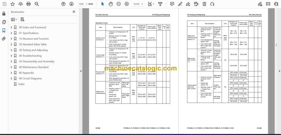