Format: PDF (Printable Document)
File Language: English
File Pages: 1242
File Size: 41.41 MB (Speed Download Link)
Brand: Komatsu
Model: PW200-7E0, PW220-7E0 Wheeled Excavator
Book No: VEBM949100
Serial No: H55051,H65051 and up
Type of Document: Shop Manual
$ 39
PW200/220-7E0 VEBM949100
CONTENTS
FOREWORD
Safety
List of revised pages
General
How to read the shop manual
Hoisting instructions
Coating materials
Standard tightening torque
Electric wire code
Conversion tables
Units
GENERAL
Specification dimension drawings
Working ranges
Specifications
Weight table
STRUCTURE AND FUNCTION, MAINTENANCE STANDARD
Engine related parts
Radiator – Oil cooler – Charge air cooler
Power train
Swing circle
Swing machinery and motor
Swing motor
Undercarriage
Transmission
Travel motor
Clutch control circuit
Axle
Suspension lock cylinder
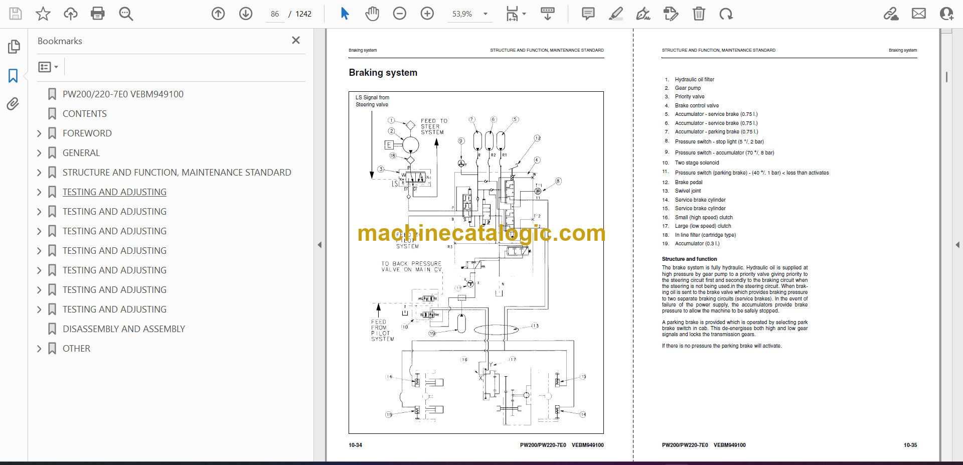
Braking system
Brake/steer pump
Priority valve
Power brake valve
Accumulator for brake system
Steering system
Steering column
Orbitrol valve
Hydraulic equipment layout drawings
Hydraulic circuit diagram
Hydraulic tank
Hydraulic pump
Pilot pressure control (PPC) system
Control valve
CLSS
Centre swivel joint
Travel PPC pedal
Work equipment – Swing PPC valve
Solenoid valves
Boom Safety valve
Hydraulic cylinder
Outrigger cylinder
Dozer cylinder
Work equipment
Air conditioner
Electrical wiring diagram
Electrical system
Engine control system
Machine monitor system
Overload warning device
Sensor
1st attachment circuit hydraulic performance (main valve bypassed)
Travel circuit
Steering system
Service brake and suspension system
Quick coupler control valve
ATT EPC valve assembly
KOMTRAX terminal system
Standard value table for engine related parts
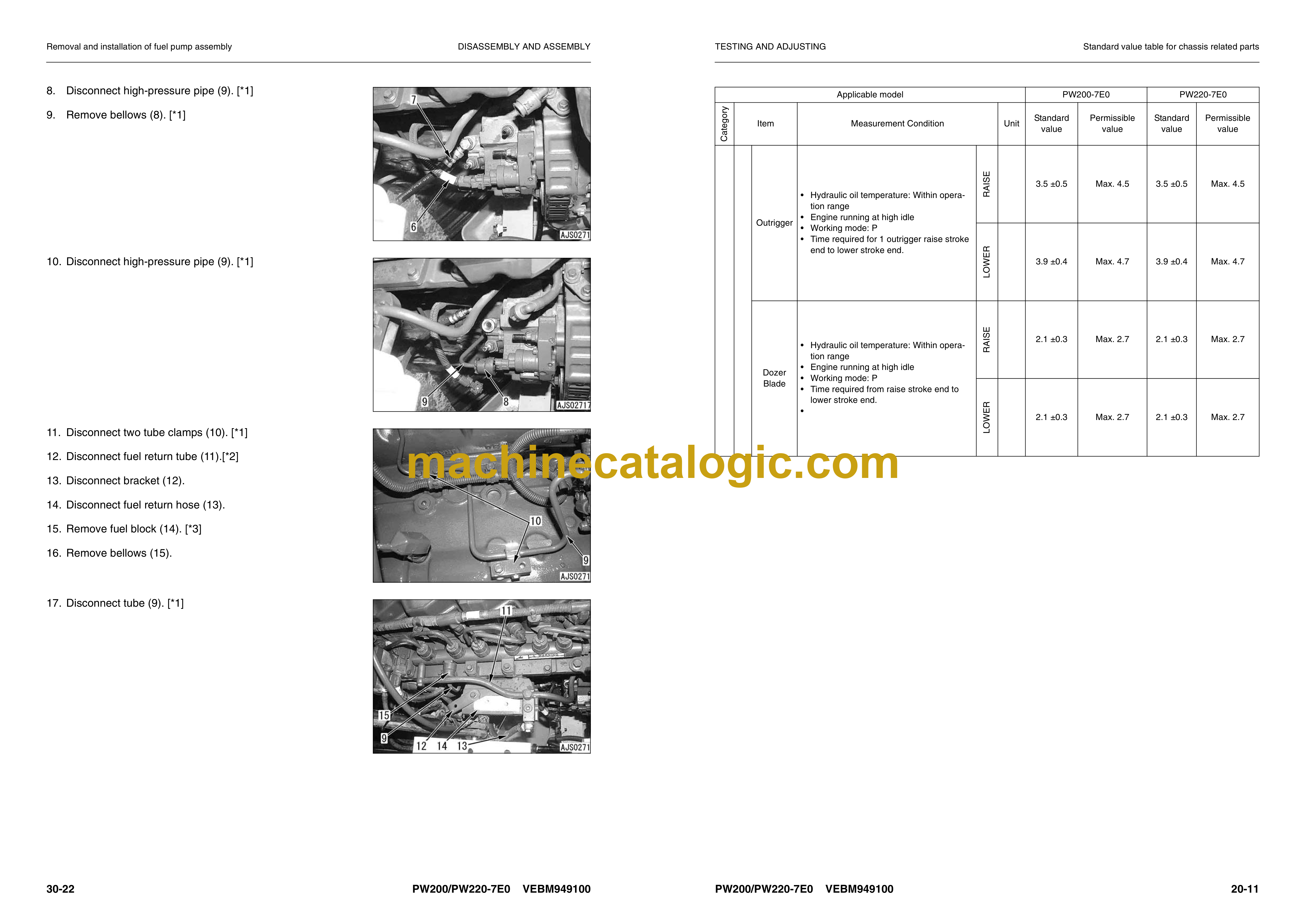
Standard value table for chassis related parts
Flow control characteristic of PC valve (STD)
TESTING AND ADJUSTING
Preparations for troubleshooting of electrical system
TESTING AND ADJUSTING
Measuring engine speed
Measuring intake air pressure (boost pressure)
Measurement of exhaust gas color
Adjusting valve clearance
Measuring compression pressure
Measurement of blow-by pressure
Measure engine oil pressure
Handling fuel system parts
Releasing residual pressure from fuel system
Measuring fuel pressure
Measuring fuel return rate and leakage
Bleeding air from fuel circuit
Checking fuel circuit for leakage
Checking and adjusting air conditioner compressor belt tension
Replacing the fan belt
Measurement of clearance in swing circle bearings
Inspection and adjustment of hydraulic oil pressure in hydraulic circuit for work equipment, swing and travel
Inspection and adjustment of control circuit oil pressure
Inspection and adjustment of pump pc (valve inlet) control oil pressure
Inspection and adjustment of pump ls valve control oil pressure
Measurement of solenoid valve output pressure
Measurement of PPC valve output pressure
Adjustment of work equipment and swing PPC valve
Measuring and adjusting quick coupler control valve output pressure
Testing travel motor relief pressure
Adjusting travel motor relief pressure
Testing propshaft speed
Testing transmission clutch control circuit
Inspection of locations of hydraulic drift of work equipment
Release of remaining pressure in hydraulic circuit
Measurement of oil leakage amount
Air bleeding of various parts
Inspection procedures for diode
Special function of monitor panel
Procedure for turning on KOMTRAX terminal
TESTING AND ADJUSTING
Troubleshooting
Points to remember when troubleshooting
Sequence of events in troubleshooting
Points to remember when carrying out maintenance
Checks before troubleshooting
Classification and steps for troubleshooting
Connector location chart and electrical circuit diagram by system
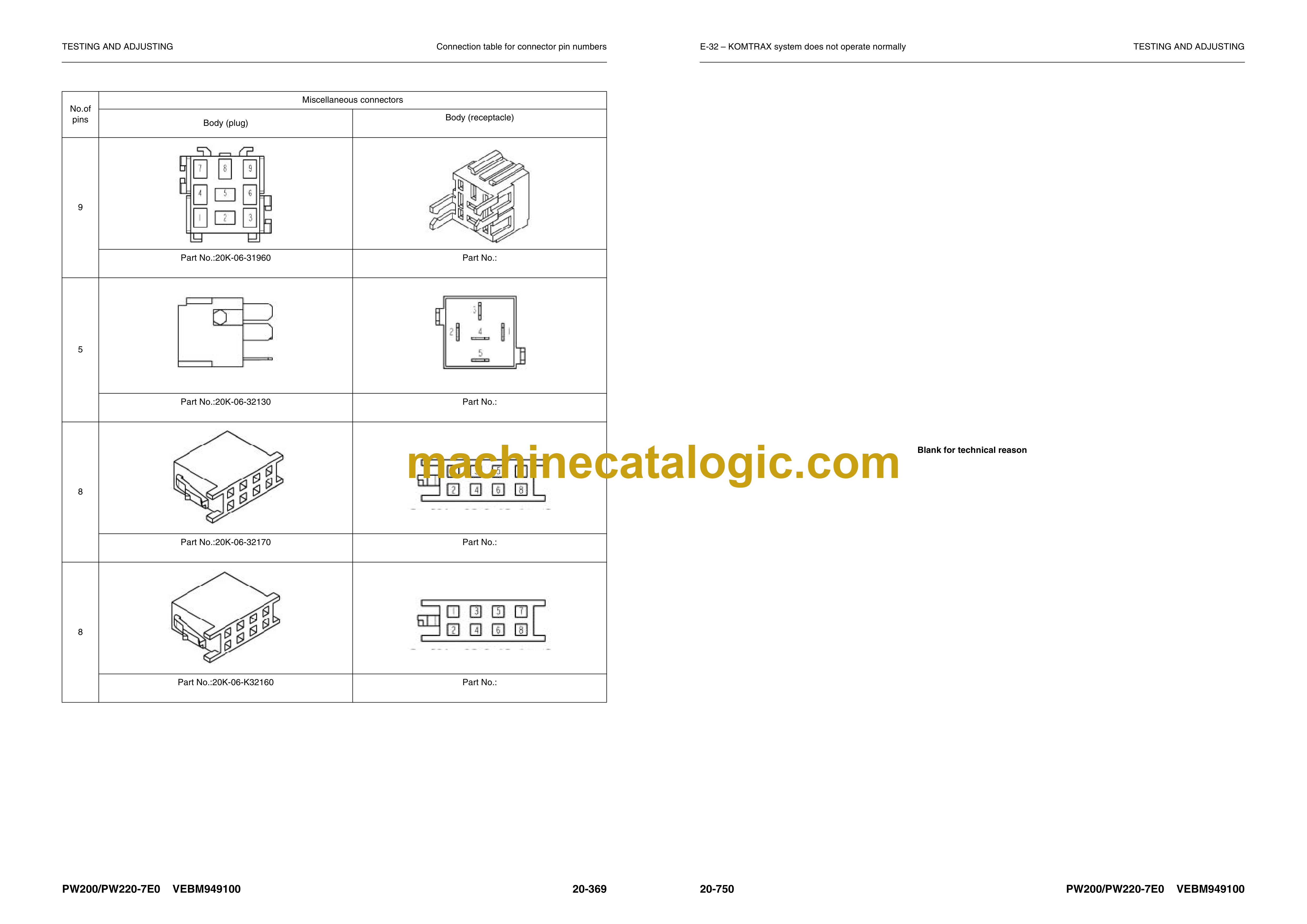
Connection table for connector pin numbers
Information contained in troubleshooting table
Failure code [6B2JMA] – Abnormality in travel PPC switch hydraulics
Failure code [989L00] – Engine controller lock caution 1
Failure code [989M00] – Engine controller lock caution 2
Failure code [989N00] – Engine controller lock caution 3
Failure code [AA10NX] – Air cleaner clogging
Failure code [AB00KE] – Charging voltage abnormally low
Failure code [B@BAZG] – Abnormally lowered engine oil pressure
Failure code [B@BAZK] – Abnormally lowered engine oil level
Failure code [B@BCNS] – Engine cooling water overheating
Failure code [B@BCZK] – Abnormally low radiator water level
Failure code [B@HANS] – Hydraulic oil overheating
Failure code [CA111] – EMC critical internal failure
Failure code [CA115] – Engine neutral and backup speed sensor error
Failure code [CA122] – Chg air press sensor high error
Failure code [CA123] – Chg air press sensor low error
Failure code [CA131] – Throttle sensor high error
Failure code [CA132] – Throttle sensor low error
Failure code [CA144] – Coolant temp sens high error
Failure code [CA145] – Coolant temp sens low error
Failure code [CA153] – Chg air temp sensor high error
Failure code [CA154] – Chg air temp sensor low error
Failure code [CA155] – Chg air temp high speed derate
Failure code [CA187] – Sens supply 2 volt low error
Failure code [CA221] – Ambient press sens high error
Failure code [CA222] – Ambient press sens low error
Failure code [CA227] – Sens supply 2 volt high error
Failure code [CA234] – Eng overspeed
Failure code [CA238] – Ne speed sens supply volt error
Failure code [CA271] – IMV/PCV1 short error
Failure code [CA272] – IMV/PCV1 open error
Failure code [CA322] – Inj #1 (L#1) open/short error
Failure code [CA323] – Inj #5 (L#5) open/short error
Failure code [CA324] – Inj #3 (L#3) open/short error
Failure code [CA325] – Inj #6 (L#6) open/short error
Failure code [CA331] – Inj #2 (L#2) open/short error
Failure code [CA332] – Inj #4 (L#4) open/short error
Failure code [CA342] – Calibration code incompatibility
Failure code [CA351] – Injectors drive circuit error
Failure code [CA352] – Sens supply 1 volt low error
Failure code [CA386] – Sens supply 1 volt high error
Failure code [CA428] – Water in fuel sensor high error
Failure code [CA429] – Water in fuel sensor low error
Failure code [CA435] – Eng oil press sw error
Failure code [CA441] – Battery voltage low error
Failure code [CA442] – Battery voltage high error
Failure code [CA449] – Rail press very high error
Failure code [CA451] – Rail press sensor high error
Failure code [CA452] – Rail press sensor low error
Failure code [CA488] – Chg air temp high torque derate
Failure code [CA553] – Rail press high error
Failure code [CA559] – Rail press low error
Failure code [CA689] – Eng ne speed sensor error
Failure code [CA731] – Eng bkup speed sens phase error
Failure code [CA757] – All continuous data lost error
Failure code [CA778] – Eng G speed sensor error
Failure code [CA1633] – KOMNET datalink timeout error
Failure code [CA2185] – Throttle sensor supply voltage high error
Failure code [CA2186] – Throttle sensor supply voltage low error
Failure code [CA2249] – Rail press very low error
Failure code [CA2311] – IMV solenoid error
Failure code [CA2555] – Grid htr relay volt high error
Failure code [CA2556] – Grid heater relay volt low error
Failure code [D110KB] – Short-circuiting in battery relay
Failure code [D19JKZ] – Personal code relay abnormality
Failure code [D862KA] – GPS antenna discon
Failure code [DA25KP] – Press. sensor power abnormality
Failure code [DA2RMC] – Pump comm. abnormality
Failure code [DA2SKA] – Disconnection of S-NET signal
Failure code [DA2SKQ] – Abnormality in inputting model code
Failure code [DA2SKQ] – Abnormality in inputting model code
Failure code [DAF0KT] – Abnormal data in error history
Failure code [DAFRMC] – Monitor comm. abnormality
Failure code [DDC3KZ] – Outrigger switch select abnormality
Failure code [DDHPAKP] – Abnormality in pump pressure sensor
Failure code [DDP4KX] – Abnormality in travel PPC pressure switch
Failure code [DDWCKZ] – Abnormality in travel direction control switch
Failure code [DFB1KZ] – Service lever potentio 1 abnormality
Failure code [DFB2KZ] – Service lever potentio 2 abnormality
Failure code [DFB3L8] – Service lever 1 potentio error
Failure code [DFB4L8] – Service lever 2 potentio error
Failure code [DGH2KB] – Hydr oil sensor short
Failure code [DH10KS] – Abnormality in pressure sensor power source
Failure code [DHPAKP] – Abnormality in F pump pressure sensor
Failure code [DHPAMA] – Abnormality in F pump pressure sensor
Failure code [DHPBMA] – Abnormality in R pump pressure sensor
Failure code [DHS5KX] – Abnormality in travel PPC sensor
Failure code [DHX1MA] – Abnormality in overload caution sensor
Failure code [DLE2MA] – Abnormality in engine rotation sensor in governor (pump controller system)
Failure code [DLT4KA] – Disconnection in transmission speed sensor in governor (pump controller syste)m)
Failure code [DW27KA] – Disconnection in transmission clutch solenoid
Failure code [DW27KB] – Short-circuiting in transmission clutch solenoid
Failure code [DW4CKA] – Disconnection in PPC lock solenoid
Failure code [DW4CKB] – PPC lock sol. S/C
Failure code [DW44KA] – Disconnection of travel F/R solenoid
Failure code [DW44KB] – Short-circuiting of travel F/R solenoid
Failure code [DW45KA] – Disconnection in swing parking brake solenoid
Failure code [DW4MKA] – Disconnection in creep solenoid
Failure code [DW4MKB] – Short-circuiting in creep solenoid
Failure code [DW91KA] – Disconnection in travel neutral solenoid
Failure code [DW91KB] – Short-circuiting in travel neutral solenoid
Failure code [DWK0KA] – Disconnection in 2-stage relief solenoid
Failure code [DWK0KB] – Short-circuiting in 2-stage relief solenoid
Failure code [DWK2KA] – Disconnection in 2-stage back pressure solenoid
Failure code [DWK2KB] – Short circuiting in 2-stage back pressure solenoid
Failure code [DXA0KA] – Disconnection in PC-EPC solenoid system
Failure code [DXE0KA] – Disconnection in LS-EPC solenoid system
Failure code [DXE0KB] – Short-circuiting in LS-EPC solenoid
Failure code [DXE4KA] – Service current EPC1 discon
Failure code [DXE4KB] – Service current EPC1 short
Failure code [DXE7KA] – Service current EPC2 disco
Failure code [DXE7KB] – Service current EPC2 short
Failure code [DXE8KA] – Service current EPC3 discon
Failure code [DXE8KB] – Service current EPC3 short
Failure code [DXE9KA] – Service current EPC4 discon
Failure code [DXE9KB] – Service current EPC4 short
Failure code [DY20KA] – Wiper working abnormality
Failure code [DY20MA] – Wiper parking abnormality
Failure code [DY2CKB] – Washer drive S/C
Failure code [DY2DKB] – Wiper drive (for) S/C
Failure code [DY2EKB] – Wiper drive (rev) S/C
TESTING AND ADJUSTING
Troubleshooting when service code “Electrical system” and failure code “Mechanical system” are indicated
Information contained in troubleshooting table
E-1 – Engine does not start (engine does not rotate)
E-5 – Auto-decelerator does not work
E-6 – Auto engine warm-up device does not work
E-7 – Preheater does not operate
E-8 – All work equipment, swing and travel do not move
E-9 – One-touch power max switch does not work
E-10 – No display in monitor panel at all
E-11 – Part of display on monitor panel is missing
E-12 – Monitor panel displays contents irrelevant to the model
E-13 – Fuel level monitor red lamp lights up while engine is running
E-14 – Engine coolant temperature gauge does not indicate normally
E-15 – Hydraulic oil temperature gauge does not display correctly
E-16 – Fuel gauge does not display correctly
E-17 – Swing lock monitor does not display correctly
E-18 – When the monitor switch is operated, no display appears
E-19 – Windshield wiper and window washer do not operate
E-20 – Alarm buzzer cannot be stopped
E-21 – “Boom/stabiliser RAISE” is not correctly displayed in monitor function
E-22 – “Boom/stabiliser LOWER” is not correctly displayed in monitor function
E-23 – “Arm DIGGING” is not correctly displayed in monitor function
E-24 – “Arm DUMPING” is not correctly displayed in monitor function
E-25 – “Bucket DIGGING” is not correctly displayed in monitor function
E-26 – “Bucket DUMPING” is not correctly displayed in monitor function
E-27 – “SWING” is not correctly displayed in monitor function
E-28 – “TRAVEL” is not correctly displayed in monitor function
E-29 – “2 piece boom” is not correctly displayed in monitor function
E-30 – Air conditioner does not work
E-31 – Travel reverse alarm does not sound
E-32 – KOMTRAX system does not operate normally
TESTING AND ADJUSTING
Troubleshooting of electrical system (E-Mode)
Information contained in troubleshooting table
Radio cassette and telephone socket
PPC lock circuit
Brake light circuit
Undercarriage attachments – Mode selection
Undercarriage attachments – Front left outrigger
Undercarriage attachments – Front right outrigger
Undercarriage attachments – Rear left outrigger
Undercarriage attachments – Rear right outrigger
Heated seat does not warm up
Suspension lock
Lower wiper does not work (optional fitment)
Work lights (operator cab front left)
Work lights (operator cab front right)
Work lights (operator cab rear)
Work lights (boom, arm and counterweight)
Cab and counterweight beacon light
Air seat compressor (option – air suspension seat)
Operator cab interior light
Cigar lighter
Park brake (not activating)
Park brake (displayed symbol)
RH PPC lever clamshell roller switch pushed to the LH position
RH PPC lever clamshell roller switch pushed to the RH position
RH PPC lever clamshell roller switch pushed to the RH or LH position
Horns
Swing lock – Normal operation
Swing lock – Emergency operation
Neutral start (engine)
Neutral start (engine) cont’d (A)
Neutral start (engine) cont’d (B)
Neutral start (engine) cont’d (C)
Emergency travel control – Forward
Emergency travel control – neutral
Emergency travel control – Reverse
Emergency travel control – Reverse cont’d
Driving lights – Main beam
Driving lights – Main beam flash
Driving lights – Main beam dipped
Driving lights – Position lights
Driving lights – Position lights cont’d (1) and (2)
Indicators – Right hand
Indicators – Left hand
Hazard warning lights
Hazard warning lights cont’d (A)
Swing lock proximity switch
TESTING AND ADJUSTING
Troubleshooting of electrical system (Error checking of items without monitor codes)
System chart for hydraulic and mechanical systems
Information contained in troubleshooting table
H-1 – All work equipment lacks power, or travel and swing speeds are slow
H-2 – Engine speed sharply drops or engine stalls
H-3 – No work equipment, travel or swing move
H-4 – Abnormal noise is heard from around hydraulic pump
H-5 – Auto-decelerator does not work
H-6 – Fine control mode does not function
H-7 – Boom moves slowly or lacks power
H-8 – Arm moves slowly or lacks power
H-9 – Bucket moves slowly or lacks power
H-10 – Work equipment does not move in its single operation
H-11 – Work equipment hydraulic drift is too fast
H-12 – Work equipment has big time lag
H-13 – Other work equipment moves when relieving single circuit
H-14 – One-touch power max. switch does not operate
H-15 – In compound operation, work equipment with larger load moves slowly
H-16 – In swing and boom RAISE operation, boom moves slowly
H-17 – In swing and travel, travel speed drops sharply
H-18 – Travel speed does not switch
H-19 – Travel speed does not shift, or it is too slow or fast
H-20 – Machine does not swing
H-21 – Swing acceleration is poor, or swing speed is slow
H-22 – Excessive overrun when stopping swing
H-23 – There is big shock when stopping swing
H-24 – There is loud abnormal noise caused when stopping swing
H-25 – Swing natural drift is too big
H-26 – Swing speed is faster than specified swing speed
Troubleshooting of engine (S-mode)
S-1 – Starting performance is poor
S-2 – Engine does not start
S-3 – Engine does not pick up smoothly
S-4 – Engine stops during operations
S-5 – Engine does not rotate smoothly
S-6 – Engine lack output (or lacks power)
S-7 – Exhaust smoke is black (incomplete combustion)
S-8 – Oil consumption is excessive (or exhaust smoke is blue)
S-9 – Oil becomes contaminated quickly
S-10 – Fuel consumption is excessive
S-11 – Oil is in coolant (or coolant spurts back or coolant level goes down)
S-12 – Oil pressure drops
S-13 – Oil level rises (entry of coolant/fuel)
S-14 – Coolant temperature becomes too high (overheating)
S-15 – Abnormal noise is made
S-16 – Vibration is excessive
TESTING AND ADJUSTING
Troubleshooting of hydraulic and mechanical system (H-Mode)
How to read this manual
Sketches of special tools
Precautions when performing operation
Removal and installation of starting motor
Removal and installation of fuel pump assembly
Removal and installation of fuel injector assembly
Removal and installation of engine front seal
Removing and installation of engine rear seal
Removal and installation of cylinder head assembly
Removal and installation of combination cooler
Removal and installation of engine and hydraulic pump assemblies
Removal and installation of fuel cooler assembly
Removal and installation of transmission and travel motor
Disassembly and assembly of transmission
Disassembly and assembly of travel motor assembly
Removal and installation of swing motor and swing machinery assembly
Disassembly and assembly of swing motor and swing machinery assembly
Removal and installation of front axle
Disassembly and assembly of front axle
Removal and installation of rear axle
Disassembly and assembly of rear axle
Removal and installation of propshaft
Removal and installation of wheel
Removal and installation of suspension lock cylinder
Disassembly and assembly of suspension lock cylinder
Removal and installation of outrigger
Disassembly and assembly of outrigger
Removal and installation of dozer blade
Disassembly and assembly of dozer blade
Removal and installation of swing circle assembly
Removal and installation of revolving frame assembly
Removal and installation of centre swivel joint
Disassembly and assembly of centre swivel joint
Removal and installation of hydraulic tank
Removal and installation of fuel tank
Removal and installation of control valve
Removal and installation of LS select valve assembly
Removal and installation of LS shuttle valve assembly
Removal and installation of pressure compensation valve assembly
Removal and installation of main relief valve assembly
Removal and installation of LS control EPC valve assembly
Removal and installation of EPC solenoid valve assembly
Removal and installation of PPC valve block assembly
Removal and installation of manifold block assembly
Removal and installation of oil seal in hydraulic pump input shaft
Disassembly and assembly of work equipment ÜPPC valve
Disassembly and assembly of hydraulic cylinder
Removal and installation of monoboom work equipment
Removal and installation of 2 piece boom work equipment
Removal and installation of air conditioner unit
Removal and installation of counterweight
Removal and installation of operator cab assembly
Removal and installation of monitor assembly
Removal and installation of governor/pump controller assembly
Removal and Installation of KOMTRAX terminal
DISASSEMBLY AND ASSEMBLY
OTHER
Lubrication
Hydraulic circuit diagram (1/3)
Hydraulic circuit diagram (2/3)
Hydraulic circuit diagram (3/3)
Electrical circuit diagram (1/7)
Electrical circuit diagram (2/7)
Electrical circuit diagram (3/7)
Electrical circuit diagram (4/7)
Electrical circuit diagram (5/7)
Electrical circuit diagram (6/7)
Electrical circuit diagram (7/7)


