The Liebherr LR 1600-2 Crawler Crane is a serious lift machine, and when it throws an electrical or hydraulic fault, the first thing a decent workshop does is grab the BMK or “outline of components.” The Technical Information & BMK Components Manual for the LR 1600-2 (SN 074519) is what your techs use to tie what they see on the schematics to the real iron on the crane. If you’re chasing a relay, valve block, sensor, or plug by its Liebherr code and need to know where it actually sits on the carrier or superstructure, this is the right book. If you’re hoping for repair steps or part numbers, this isn’t it.
What this manual helps you do
- Identify which physical component matches a schematic tag like K15, V3, or X45 on the LR 1600-2.
- Locate sensors, valves, junction boxes, and harness plugs on both the crawler carrier and the upper crane body.
- Trace wiring or hydraulic lines from a diagram reference to the actual mounting point on the machine.
- Cross-reference Liebherr component IDs to the names and locations used in other LR 1600-2 documentation.
- Pinpoint components when training new techs so they learn the machine layout faster and stop guessing.
Who this is for
This is aimed at workshop technicians, field service techs, electrical diagnostic engineers, fleet mechanics, and training instructors. If you need fault-finding procedures, repair methods, or OEM part numbers, you want the service manual or parts catalogue instead, not this BMK.
FAQ
Q: Is the PDF clear and searchable?
A: Yes, these are normally supplied as readable PDF scans where diagrams and ID labels are clear enough to zoom and search by code.
Q: Does it cover both carrier and superstructure?
A: Yes, this Technical Information & BMK Components Manual combines the component identification for the crawler carrier and the superstructure in one product.
Q: Does it work with other Liebherr manuals?
A: Yes, the BMK is meant to be used alongside wiring diagrams, hydraulic schematics, service manuals, and parts catalogues so you can go from code to location to part.
Bottom line: If your main need is to identify and physically find LR 1600-2 components by their Liebherr codes on SN 074519, this is exactly what you want. If you’re after “how to fix it” or “what part to order,” this is the wrong document.
📘 Show Index
Table of Contents:
Carrier — Table of Contents
- Vergleich
- LR 1600/2 und LR 1600/2-W
- Raupenträger
- Elektrik Raupenträger
- Fahrantrieb Sensorik
- Fahrantrieb
- Kettenspanner
- Mittelteil breites Fahrwerk
- Hydraulische Montage-Abstützung
- Drehdurchführung:
- Elektrik
- Übersicht:
- Topf
- Neigungssensor
- Drehdurchführung Drehbühne / Topf
- Schaltschrank
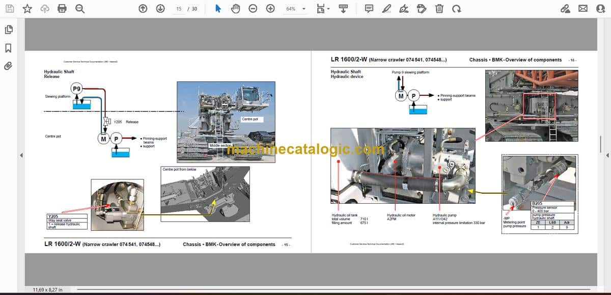
- Hydraulische Welle
- Freigabe
- Hydraulik-Aggregat
- Betrieb Abstützung ohne Drehbühne
- Abstützung
- Übersicht
- Beleuchtung
- CAN-Ventilblock Verbolzung-Abstützholme vorne
- CAN-Ventilblock Verbolzung-Abstützholme hinten
- Ventilblock-Abstützung
- Längengeber-Abstützholm
- Druckgeber Abstützzylinder
- Elektro-Steckverbindungen Abstützholm / Topf
- Hydraulik-Kuppelstellen Abstützholm / Topf
- Mittelteil Schmale-Raupe:
- Index
Superstructure — Table of Contents
- LR 1600/2 Drehbühne
- ab 074 505
- Übersicht:
- Kabine:
- Steuerstand:
- Monitore, Pedale
- Meisterschalter, LSB-BKE
- Meisterschalter 1 rechts
- Meisterschalter 2 links
- Seitenkonsole – Bedienelemente
- Seitenkonsole – Bedienelemente
- Dachkonsole
- Einsatzplaner auf BSE
- Kameraüberwachung
- Kabineninstallation:
- Radio und Innenbeleuchtung
- 12 Volt Netz
- Wisch- Waschanlage
- LMB-Warneinrichtungen
- Kabinenaufstiegs-Leiter „Schmale Raupe“
- Heizung / Klima
- Heiz- und Klima-Gerät
- Temperatursensoren
- Klimaanlage
- Zusatzheizung „Thermo 90 ST
- Elektrik Drehbühne:
- Blatteriekasten
- Sicherungen
- Blatterieladegerät
- Fremdeinspeisung
- Steckverbindungen
- Drehbühne – Ausleger
- Drehbühne – Schaltschrank
- Schaltschrank
- Zentraleinheiten
- Eingangsplatinen
- Steckverbindungen auf Eingangsplatinen
- EA-Modul 6, Datenlogger
- Sicherungen
- Relaisträger
- Relais unter Schwenkrahmen 1
- Notbetrieb
- Vorwiderstände-Notbetrieb
- Funktionsbausteine
- Zentralschmieranlage:
- Antriebsaggregat:
- Dieselmotor D846 A7 CR 370 kW / 496 PS:
- Einbauansicht
- Einspritzseite
- Abgasseite
- Motoransicht Schwungradseite
- Motoransicht oben
- Kraftstoff-Pumpen
- Kraftstoff-Service-Center KSC
- Kraftstoff-Hochdrucksystem
- Drehzahl-Sensoren
- Ladeluft-Sensoren
- Wassergekühlte externe Abgasrückführung
- Flammstartanlage
- Kühlmittel-Niveau und -Temperatur
- Motorsteuergerät, Luftfilter-Unterdruck
- Diesel-Kraftstoffanlage:
- Kraftstoff-Vorfiltereinheit
- Druckluftanlage:
- Kompressor, Trockner
- Motorbremse und Klappe in Ansaugluft
- Kranhydraulik:
- Pumpenverteilergetriebe
- Hydrauliköltank
- Hydrauliköl-Kühler
- Hydraulikpumpen
- Anordnung an PVG
- Übersicht 1
- Übersicht 2
- Beschreibung Pumpen A11VO (DRG); Pumpe 9, 10
- Beschreibung Pumpen A10VO (ED) Pumpe 7
- Beschreibung Pumpen A4VG; Pumpe 1 bis 6, 12, 14
- Drucksensoren
- Druckstufenventile Pumen 9, 10
- Speisedruck-Versorgung Pumpe 8
- Pumpen 3 und 4 auf Raupenfahrwerk
- Lüfterrad-Kombikühler
- Nebenverbraucher
- Druckversorgung von Pumpe 9
- Kabine kippen
- Kabine schwenken
- Leiter schwenken
- Bolzenziehzylinder S-, D- und SA-Bock
- Montagewinde
- Drehwerk
- Druckversorgung
- Ansteuerung
- Drehwerk 1 bis 3
- S-, D- und SA-Rückfallzylinder
- Handbetätigung
- Druckversorgung S- und D-Rückfallzylinder
- Druckversorgung SA-Bock-Rückfallzylinder
- Druckversorgung SA-Bock-Rückfallzylinder
- Winden im Drehbühnenrahmen
- Übersicht
- Windendrehgeber Winden 1, 2, 4
- Winde 1 und 2
- Versorgung Winde 1 und 2
- Hydraulikanschlüsse Winde 1 und 2
- Ansteuerung Winde 1
- Ansteuerung Winde 2
- Winde 4
- Haupt-Ausleger
- S-Anlenkstück
- Hydraulikverbindungen
- Elektro-Installation
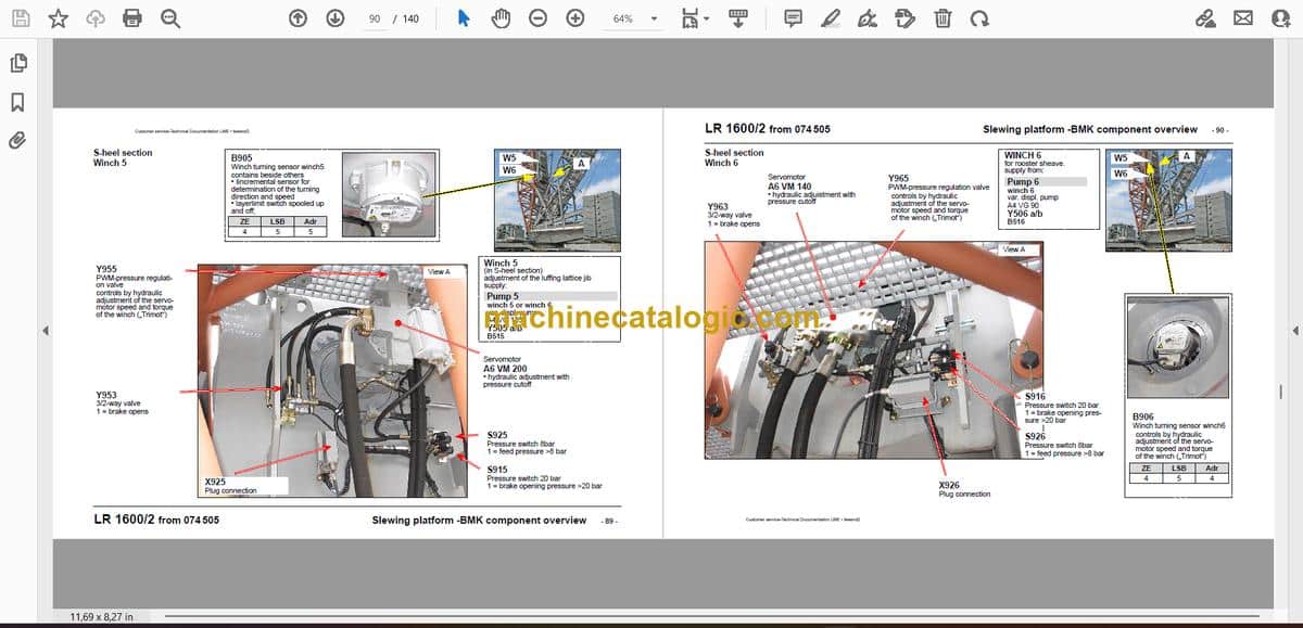
- Winde 5
- Winde 6
- Kraftmessachsen in S-Rückfallzylinder
- Sensoren S-Rückfallzylinder
- S/W-Kopfstück als S-Kopfstück
- „Derrick“-Ausleger D
- Sensorik
- „Derrick“-Anlenkstück-Rückfallzylinder
- Rückfallzylinder
- Winde 3
- Druckgeber Zugzylinder
- Zugzylinder-Sperrventile
- Zugzylinder heben / senken
- Aufstellbock („SA-Bock“)
- Sensorik
- Raupen-Montagevorrichtung („SA-Bock“)
- Kraftmessstellen
- Ballastpalette B
- Wippbare Gitterspitze W
- Übersicht
- W-Anschlusskopf
- W-Anlenkstück
- S/W-Kopfstück
- WA-Bock 1
- Feste Gitterspitze F
- F-Anschlußkopf und Kopfstück
- Mastnase H 36 t (Typ 1)
- Ballastwagen BW
- Übersicht
- Führungsrohr
- Verbolzung Drehbühne / Ballastwagen
- Hydraulik und Elektrik
- Ansteuerung Ausschiebezylinder
- Abstützung-Ballastwagen
- Radsatz
- Ansteuerung Radeinschlag
- Drehgeber
- Antrieb
- Hydromotor
- Ventile
- Schaltschrank-Antrieb
- Drehdurchführung
- Elektrik-Ballastwagen
- Schaltschrank
- Schaltschrank
- Schaltschrank
- Bedienpulte A1210 und A1220
- Bedienpult A1230
- Adapter Ballastwagen LR 1750
- Sonderausstattung
- Hydraulik-Aggregatwagen
- Hydraulische Notbetätigung
- Montageplatte Notbetrieb
- Montageplatte Parallelbetrieb
- Index
Liebherr Crane


