The Liebherr LR 1600-2 Crawler Crane is usually on critical, planned lifts where downtime kills your schedule and budget. This Technical Information & BMK Components Manual for SN 074525 is what your techs reach for when a schematic says “K15” or “X45” and they need to know where that is on the machine. Component identification matters because if you can’t find it, you can’t test it, and you can’t plan parts or downtime accurately. This isn’t about how to fix the crane; it’s about knowing exactly where everything lives on both carrier and superstructure.
What this manual helps you do
- Identify which physical component matches a reference like E1, V12, K3, or X45 shown on wiring or hydraulic diagrams.
- Locate sensors, valves, relays, control units, and junction boxes on the LR 1600-2 using clear outline and layout diagrams.
- Trace harness routes and hydraulic runs on the carrier and superstructure so you can plan access, testing, and removal work.
- Cross-reference Liebherr component IDs to other documents (wiring diagrams, service info) when chasing a fault code.
- Pinpoint components during technician training so new staff learn the machine layout faster and make fewer “where is it?” calls.
Who this is for
This suits a workshop technician, field service tech, electrical diagnostic engineer, fleet mechanic, or training instructor who already has service and parts books. If you need repair procedures, torque values, or part numbers, you want the service manual and parts catalogue instead, not this BMK.
FAQ
Q: Is the PDF clear and searchable for diagrams and IDs?
A: Yes, it’s a PDF with readable component outlines and designators you can zoom and search by text.
Q: Does it cover both the undercarriage and the upper crane?
A: Yes, it combines BMK component identification for both the carrier and the superstructure.
Q: Does it tie in with Liebherr wiring diagrams or service manuals?
A: Yes, the BMK links component IDs to items used in wiring diagrams and other Liebherr technical documents.
Bottom line: If your main problem is “I see it on the schematic but can’t find it on the crane,” this BMK component identification manual is exactly what you need. If you’re after how-to repair steps or parts ordering, it’s the wrong book.
📘 Show Index
Table of Contents:
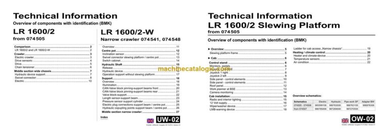
Carrier — Table of Contents
- Vergleich
- LR 1600/2 und LR 1600/2-W
- Raupenträger
- Elektrik Raupenträger
- Fahrantrieb Sensorik
- Fahrantrieb
- Kettenspanner
- Mittelteil breites Fahrwerk
- Hydraulische Montage-Abstützung
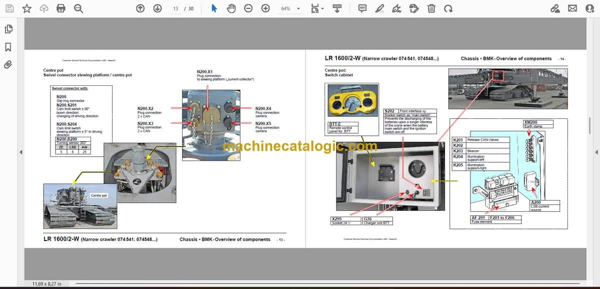
- Drehdurchführung:
- Elektrik
- Übersicht:
- Topf
- Neigungssensor
- Drehdurchführung Drehbühne / Topf
- Schaltschrank
- Hydraulische Welle
- Freigabe
- Hydraulik-Aggregat
- Betrieb Abstützung ohne Drehbühne
- Abstützung
- Übersicht
- Beleuchtung
- CAN-Ventilblock Verbolzung-Abstützholme vorne
- CAN-Ventilblock Verbolzung-Abstützholme hinten
- Ventilblock-Abstützung
- Längengeber-Abstützholm
- Druckgeber Abstützzylinder
- Elektro-Steckverbindungen Abstützholm / Topf
- Hydraulik-Kuppelstellen Abstützholm / Topf
- Mittelteil Schmale-Raupe:
- Index
Superstructure — Table of Contents
- LR 1600/2 Drehbühne
- ab 074 505
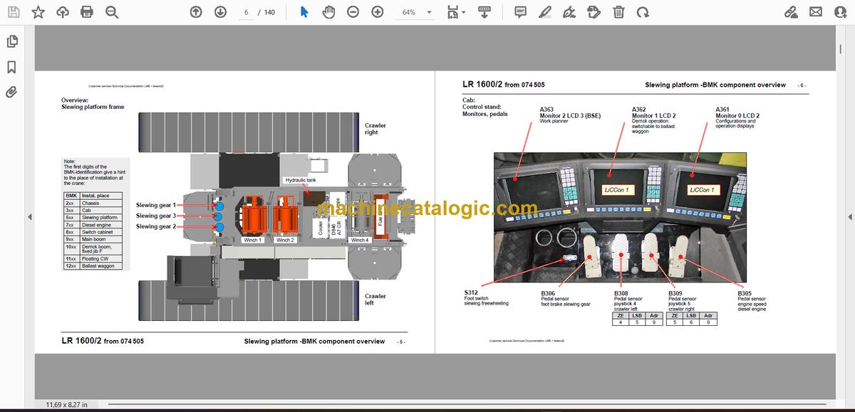
- Übersicht:
- Kabine:
- Steuerstand:
- Monitore, Pedale
- Meisterschalter, LSB-BKE
- Meisterschalter 1 rechts
- Meisterschalter 2 links
- Seitenkonsole – Bedienelemente
- Seitenkonsole – Bedienelemente
- Dachkonsole
- Einsatzplaner auf BSE
- Kameraüberwachung
- Kabineninstallation:
- Radio und Innenbeleuchtung
- 12 Volt Netz
- Wisch- Waschanlage
- LMB-Warneinrichtungen
- Kabinenaufstiegs-Leiter „Schmale Raupe“
- Heizung / Klima
- Heiz- und Klima-Gerät
- Temperatursensoren
- Klimaanlage
- Zusatzheizung „Thermo 90 ST
- Elektrik Drehbühne:
- Blatteriekasten
- Sicherungen
- Blatterieladegerät
- Fremdeinspeisung
- Steckverbindungen
- Drehbühne – Ausleger
- Drehbühne – Schaltschrank
- Schaltschrank
- Zentraleinheiten
- Eingangsplatinen
- Steckverbindungen auf Eingangsplatinen
- EA-Modul 6, Datenlogger
- Sicherungen
- Relaisträger
- Relais unter Schwenkrahmen 1
- Notbetrieb
- Vorwiderstände-Notbetrieb
- Funktionsbausteine
- Zentralschmieranlage:
- Antriebsaggregat:
- Dieselmotor D846 A7 CR 370 kW / 496 PS:
- Einbauansicht
- Einspritzseite
- Abgasseite
- Motoransicht Schwungradseite
- Motoransicht oben
- Kraftstoff-Pumpen
- Kraftstoff-Service-Center KSC
- Kraftstoff-Hochdrucksystem
- Drehzahl-Sensoren
- Ladeluft-Sensoren
- Wassergekühlte externe Abgasrückführung
- Flammstartanlage
- Kühlmittel-Niveau und -Temperatur
- Motorsteuergerät, Luftfilter-Unterdruck
- Diesel-Kraftstoffanlage:
- Kraftstoff-Vorfiltereinheit
- Druckluftanlage:
- Kompressor, Trockner
- Motorbremse und Klappe in Ansaugluft
- Kranhydraulik:
- Pumpenverteilergetriebe
- Hydrauliköltank
- Hydrauliköl-Kühler
- Hydraulikpumpen
- Anordnung an PVG
- Übersicht 1
- Übersicht 2
- Beschreibung Pumpen A11VO (DRG); Pumpe 9, 10
- Beschreibung Pumpen A10VO (ED) Pumpe 7
- Beschreibung Pumpen A4VG; Pumpe 1 bis 6, 12, 14
- Drucksensoren
- Druckstufenventile Pumen 9, 10
- Speisedruck-Versorgung Pumpe 8
- Pumpen 3 und 4 auf Raupenfahrwerk
- Lüfterrad-Kombikühler
- Nebenverbraucher
- Druckversorgung von Pumpe 9
- Kabine kippen
- Kabine schwenken
- Leiter schwenken
- Bolzenziehzylinder S-, D- und SA-Bock
- Montagewinde
- Drehwerk
- Druckversorgung
- Ansteuerung
- Drehwerk 1 bis 3
- S-, D- und SA-Rückfallzylinder
- Handbetätigung
- Druckversorgung S- und D-Rückfallzylinder
- Druckversorgung SA-Bock-Rückfallzylinder
- Druckversorgung SA-Bock-Rückfallzylinder
- Winden im Drehbühnenrahmen
- Übersicht
- Windendrehgeber Winden 1, 2, 4
- Winde 1 und 2
- Versorgung Winde 1 und 2
- Hydraulikanschlüsse Winde 1 und 2
- Ansteuerung Winde 1
- Ansteuerung Winde 2
- Winde 4
- Haupt-Ausleger
- S-Anlenkstück
- Hydraulikverbindungen
- Elektro-Installation
- Winde 5
- Winde 6
- Kraftmessachsen in S-Rückfallzylinder
- Sensoren S-Rückfallzylinder
- S/W-Kopfstück als S-Kopfstück
- „Derrick“-Ausleger D
- Sensorik
- „Derrick“-Anlenkstück-Rückfallzylinder
- Rückfallzylinder
- Winde 3
- Druckgeber Zugzylinder
- Zugzylinder-Sperrventile
- Zugzylinder heben / senken
- Aufstellbock („SA-Bock“)
- Sensorik
- Raupen-Montagevorrichtung („SA-Bock“)
- Kraftmessstellen
- Ballastpalette B
- Wippbare Gitterspitze W
- Übersicht
- W-Anschlusskopf
- W-Anlenkstück
- S/W-Kopfstück
- WA-Bock 1
- Feste Gitterspitze F
- F-Anschlußkopf und Kopfstück
- Mastnase H 36 t (Typ 1)
- Ballastwagen BW
- Übersicht
- Führungsrohr
- Verbolzung Drehbühne / Ballastwagen
- Hydraulik und Elektrik
- Ansteuerung Ausschiebezylinder
- Abstützung-Ballastwagen
- Radsatz
- Ansteuerung Radeinschlag
- Drehgeber
- Antrieb
- Hydromotor
- Ventile
- Schaltschrank-Antrieb
- Drehdurchführung
- Elektrik-Ballastwagen
- Schaltschrank
- Schaltschrank
- Schaltschrank
- Bedienpulte A1210 und A1220
- Bedienpult A1230
- Adapter Ballastwagen LR 1750
- Sonderausstattung
- Hydraulik-Aggregatwagen
- Hydraulische Notbetätigung
- Montageplatte Notbetrieb
- Montageplatte Parallelbetrieb
- Index
Liebherr Crane


