Format: PDF (Printable Document)
File Language: English
File Pages: 144
File Size: 24.47 MB (Speed Download Link)
Brand: Liebherr
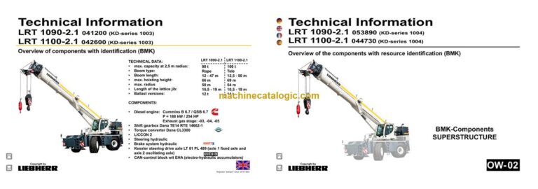
Model: LRT 1100-2.1 Rough Terrain Crane
Components: Carrier + Superstructure
Serial No: SN 044848
Date: 2024
Type of Document: Technical Information & BMK Components Manual
$ 80
The Liebherr LRT 1100-2.1 Rough Terrain Crane is a serious piece of kit, and when something’s acting up, the first thing good techs want to know is: where is that component actually mounted on the machine? That’s exactly where a BMK / component identification manual comes in. Workshop techs, field service, and trainers reach for this when a wiring diagram says “K15” or “V12” and they need to see it on the actual crane. If your main pain is “I can see it on the schematic, but not on the crane,” this BMK document is usually the fix.
What this manual helps you do
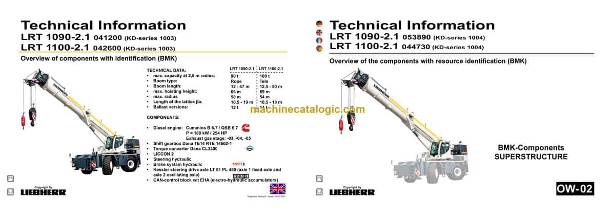
The Technical Information & BMK Components Manual for the Liebherr LRT 1100-2.1 Rough Terrain Crane provides component identification diagrams, reference designators, and visual outlines used by technicians cross-referencing wiring or hydraulic schematics to physical parts on the crane. These manuals typically show layout views of both the carrier and superstructure so new techs can learn the machine’s “geography” and avoid the classic mistake of chasing the wrong component.
Who this is for
This suits workshop technicians, field service techs, electrical diagnostic engineers, fleet mechanics, and training instructors. If you need repair procedures, torque specs, or part numbers, you want a service manual or parts catalogue instead, not this BMK.
FAQ
Q: Is the PDF clear and searchable enough to zoom in on component diagrams?
A: Yes, these are normally supplied as a readable PDF where you can zoom into layout views and search by component ID or designator text.
Q: Does this cover both the carrier and the superstructure layouts?
A: Yes, this product combines BMK information for both the carrier (undercarriage/chassis) and the superstructure (upper crane body).
Q: Does it work together with wiring diagrams and parts catalogues?
A: Yes, it’s meant to be used alongside Liebherr schematics, service information, and parts catalogues so you can go from fault code → schematic symbol → physical component.
Bottom line: If your goal is component identification and location on the LRT 1100-2.1, this is the right manual; if you want how-to-repair steps or part numbers, it’s not.
Chassis:……………………………………………………………………………….4
View from front, lighting…………………………………………………………….4
View from rear, lighting……………………………………………………………..5
Lighting support, EMERGENCY-STOP……………………………………….6
Battery, main fuse box………………………………………………………………7
I/O- modules, BTB, ECU……………………………………………………………8
Fuses, diagnostics- and emergency operation plug………………………9
Relay, distributor…………………………………………………………………….10
Diagnosis plug………………………………………………………………………. 11
► Diesel engine Cummins:……………………………………………………..12
Installation overview……………………………………………………………….12
Type plate on engine………………………………………………………………13
Overview fan side…………………………………………………………………..14
Overview injection side……………………………………………………………15
Overview exhaust side…………………………………………………………….16
Overview of exhaust side stage IV with eAGR……………………………17
Overview of exhaust side Power Band H w/o AGR……………………..17
Top view………………………………………………………………………………..18
Top view stage IV engine…………………………………………………………19
Top view Power Band H engine………………………………………………..19
Overview fly-wheel side…………………………………………………………..20
Overview fly-wheel side…………………………………………………………..21
Engine Control Module ECM……………………………………………………22
Engine control unit ECM………………………………………………………….23
Engine-CAN…………………………………………………………………………..24
Fuel scheme ( high- and low pressure)……………………………………..25
Common-Rail-System …………………………………………………………….26
Common-Rail-system Power Band H………………………………………..27
Common-Rail-system stage IV…………………………………………………28
Injectors………………………………………………………………………………..29
Injectors………………………………………………………………………………..30
Fuel prefilter…………………………………………………………………………..30
Air sensors…………………………………………………………………………….31
Air-sensors on stage IV devices……………………………………………….32
Air-sensors Power Band H engine…………………………………………….33
Speed sensors……………………………………………………………………….34
Speed sensors……………………………………………………………………….35
Cooling agent…………………………………………………………………………36
Oil circuit……………………………………………………………………………….37
Exhaust gas turbo charger……………………………………………………….38
Exhaust gas turbo charger for stage IV engines…………………………39
Exhaust gas turbo charger for Power Band H engines ……………….40
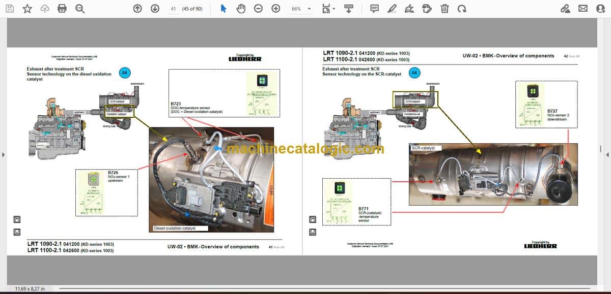
► Exhaust after treatment SCR……………………………………………….41
Copyright by
liebherr
Customer Service-Technical Documentation LWE
Originator: lwehap3 / Issue: 07.07.2021
UW-02 • BMK – Overview of components 2 from 86 LRT 1100-2.1 042600 (KD-series 1003)
LRT 1090-2.1 041200 (KD-series 1003)
Note:
All stated pressures according to state June 2021 !
Schematics Chassis Version
Electric 98023938 003
Hydraulic/
pneumatic system
98025944 005
* = Customer‘s spec.
Sensor technology on the diesel oxidation catalyst……………………..41
Sensor technology on the SCR-catalyst…………………………………….42
Mixing tube……………………………………………………………………………43
Exhaust after treatment system:……………………………………………….44
Overview……………………………………………………………………………….44
Exhaust system – module overview…………………………………………..45
Exhaust gas system – sensor technology…………………………………..46
AdBlue-pump module……………………………………………………………..47
AdBlue tank and tank gauge unit ……………………………………………..48
Dosing unit AdBlue…………………………………………………………………49
Cooling system:……………………………………………………………………50
Cooler installation…………………………………………………………………..50
Diesel fuel system:……………………………………………………………….51
Fuel prefilter and tank……………………………………………………………..51
► Shift gearbox:……………………………………………………………………..52
Dana TE14 RTE14662-1…………………………………………………………52
► Torque converter:……………………………………………………………….54
Dana CL 3300………………………………………………………………………..54
► Hydraulic:…………………………………………………………………………..55
Temperature sensor hydraulic oil, hydraulic oil tank…………………….55
Pumps – steering, support, axle suspension……………………………….56
Pumps – steering ……………………………………………………………………57
Crane hydraulic – pumps………………………………………………………….58
► Drive train:………………………………………………………………………….59
Overview……………………………………………………………………………….59
► Axle oscillation:………………………………………………………………….60
Oscillating axle……………………………………………………………………….60
Transversal differential lock……………………………………………………..61
► Steering:…………………………………………………………………………….62
Control block (change over block)…………………………………………….62
Switching emergency steering pump, deficiency monitoring, steering gear.
63
Turn sensor……………………………………………………………………………64
Steering cylinder…………………………………………………………………….65
► Brake:…………………………………………………………………………………66
Overview brake system…………………………………………………………..66
Activation………………………………………………………………………………67
Activation………………………………………………………………………………68
► Support:……………………………………………………………………………..69
Inclination sensor, support cylinder…………………………………………..69
Oil supply support…………………………………………………………………..70
Support valves – left………………………………………………………………..71
Support valves – right………………………………………………………………72
Monitoring support pressure with pressure sensor………………………75
Inductive sensor extending support…………………………………………..76
► Special equipment:……………………………………………………………..78
Ballast cylinder……………………………………………………………………….78
Eddy current brake Telma ……………………………………………………….79
Air-conditioner………………………………………………………………………..80
Cooling water preheating ………………………………………………………..81
Additional heating Airtop 2000 STC gearbox / converter ……………..82
Additional heating DBW 2016 ………………………………………………….83
► Index………………………………………………………………………………….84
► Haftungsbegrenzung / Disclaimer………………………………………..86
► Superstructure general:………………………………………………………..3
Lighting slewing platform / boom………………………………………………..3
LMB warning device (EN 13000)………………………………………………..4
Central greasing device…………………………………………………………….5
Boom direction…………………………………………………………………………6
► Crane cabin:…………………………………………………………………………7
Heating heat exchanger……………………………………………………………7
Heating – activation, temperature sensors……………………………………8
Wiper motors, washer pump, platform…………………………………………9
Interior furnishing……………………………………………………………………10
Controls cab:……………………………………………………………………….11
Liccon – monitor, pedals, ethernet……………………………………………. 11
Joystick right, key board LSB-CAB1………………………………………….12
Joystick left, support control unit LSB-AST3……………………………….13
Operation- and control unit………………………………………………………14
Switch cabinet crane cabin:………………………………………………….15
Fuses……………………………………………………………………………………15
Relay, resistor modules…………………………………………………………..16
Mounting plate – LSB-master, voltage converter…………………………17
Universal in/output module, data logger II………………………………….18
Diagnosis plug, remote diagnosis……………………………………………..19
Plug plate slewing platform / cab………………………………………………20
EMERGENCY OPERATION – XNOT – plug………………………………..21
EMERGENCY OPERATION resistors, air circulation…………………..22
► Crane hydraulic:…………………………………………………………………23
Temperature sensor and oil cooler……………………………………………24
Overview hydraulic components……………………………………………….25
Overview metering connector plate…………………………………………..26
Main control block (Bucher)……………………………………………………..27
Main control block (Bucher)……………………………………………………..28
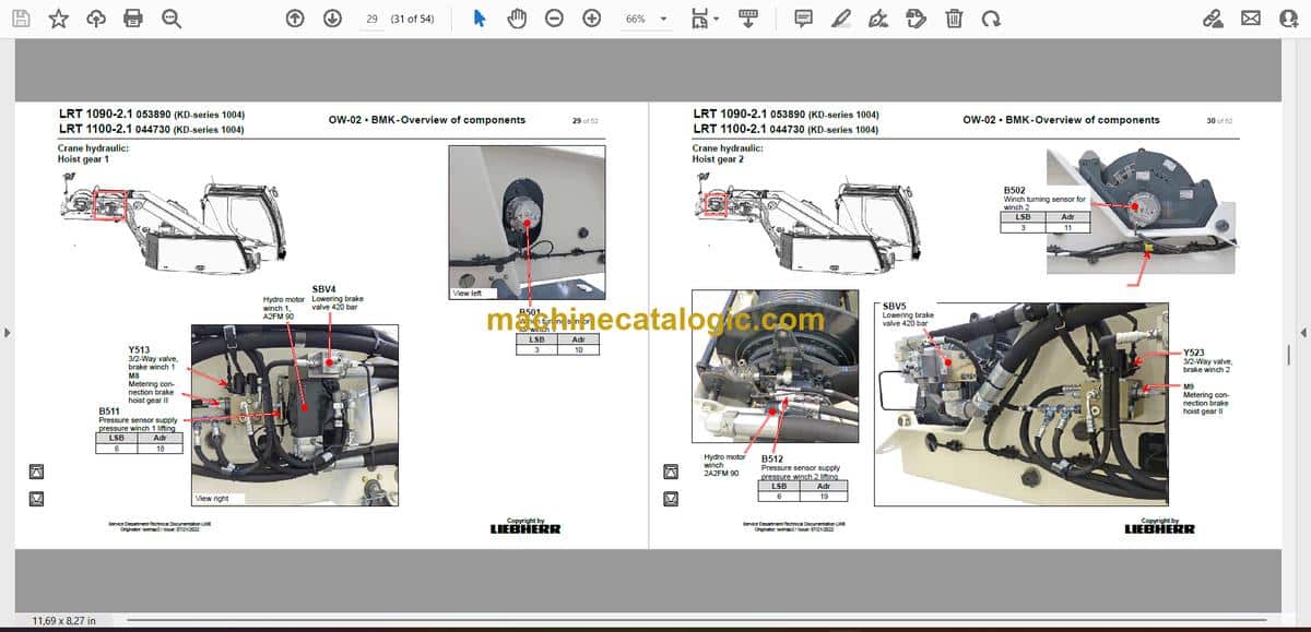
Hoist gear 1…………………………………………………………………………..29
Hoist gear 2…………………………………………………………………………..30
Luffing…………………………………………………………………………………..31
Slewing gear – activation………………………………………………………….32
Slewing gear – brake, locking……………………………………………………33
Auxiliary consumer valves……………………………………………………….34
Cab tilting………………………………………………………………………………35
► Rope boom LRT 1090-2.1:……………………………………………………36
base section, “boom steep”……………………………………………………..36
Boom head……………………………………………………………………………37
Hydraulic……………………………………………………………………………….38
► Telescopic boom LRT 1100-2.1:……………………………………………39
base section, “boom steep”……………………………………………………..39
Boom head……………………………………………………………………………40
Tele section pinning, position sensor…………………………………………41
Cylinder pinning, position sensor………………………………………………42
Hydraulic……………………………………………………………………………….43
► Ballasting……………………………………………………………………………44
► Special equipment:……………………………………………………………..45
Double swing away jib* – electric………………………………………………45
Double swing away jib* + swing away jib slewing……………………….46
Additional heating Airtop 2000ST……………………………………………..47
Camera monitoring (basic set up)……………………………………………..48
Emergency control crane hydraulic*………………………………………….49
► Index………………………………………………………………………………….50


