The Liebherr LTM 1100-5.2 Mobile Crane earns its keep on sites where you’re juggling road travel, setup, and precise lifts all day long. When something’s acting up, the first person who reaches for the BMK is usually the tech with a laptop in one hand and a fault code in the other. Component identification is what keeps you from wasting an hour pulling covers just to find one relay or valve buried in the carrier. The Technical Information & BMK Components Manual for Liebherr LTM 1100-5.2 Mobile Crane provides component identification diagrams, reference designators, and visual outlines used by technicians cross-referencing wiring or hydraulic schematics to physical parts on the crane.
What this manual helps you do
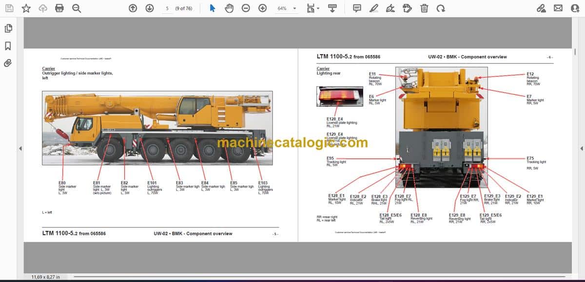
- Identify where each electrical, hydraulic, and mechanical component sits on the carrier and superstructure for SN 065894.
- Locate items from wiring diagrams (like K, V, X, E numbers) on actual machine views so you can get hands on the right part fast.
- Trace harness routes and component groupings using outline and layout views of the crane.
- Cross-reference Liebherr reference designators to the correct item names used in other Liebherr manuals.
- Match fault codes or schematic symbols to the physical relay, sensor, valve, or connector you need to test or swap.
Who this is for
This is aimed at workshop technicians, field service techs, electrical diagnostic engineers, fleet mechanics, and training instructors. If you’re after step‑by‑step repair procedures, torque specs, or part numbers, you want the service manual and parts catalogue instead of this BMK component identification book.
FAQ
Q: Are the diagrams clear and searchable in the PDF?
A: Yes, this type of BMK manual is usually supplied as a readable PDF with clear component outlines and text that you can search by ID.
Q: Does it cover both carrier and superstructure layouts?
A: Yes, this product combines the BMK for the carrier and the BMK for the superstructure into one Technical Information & BMK Components Manual.
Q: Does it work with other Liebherr documents like wiring diagrams?
A: Yes, the whole point is to tie the reference designators in your wiring, hydraulic, or service documents to the exact physical components on the crane.
Bottom line: If you need to find and name components on an LTM 1100-5.2 (SN 065894) and tie them to Liebherr schematics, this is the right manual; if you want repair steps or parts lists, it’s not.
📘 Show Index
Table of Contents:
Carrier — Table of Contents
- Fahrzeug
- Beleuchtung vorne, Spiegel
- Schiebeholmbeleuchtung / Seitenmarkierungsleuchtenrechts
- Schiebeholmbeleuchtung / Seitenmarkierungsleuchten links
- Beleuchtung hinten
- Ansicht von hinten, Steckdosen, Warnsignalgeber
- Fahrerhaus
- Türen und Fenster, Innenbeleuchtung
- Lüftung und Wärmetauscher
- Bedienelemente
- Batterien und Hauptsicherungskasten
- Mittelkonsole – E/A-Module und Diagnosestecker
- Mittelkonsole – Relais
- Mittelkonsole – Sicherungen
- Mittelkonsole – Bestückungsmodul, Spannungswandler
- Druckluftanlage
- Druckgeber und Ventile der Bremsanlage
- Kompressor und Trockner
- Ventilblock Hilfsverbraucher
- Dieselmotor D 846 TI A7, 370 kW/503 PS (Common Rail)
- Motoransicht links
- Motoransicht rechts
- Motoransicht Schwungradseite
- Motoransicht oben
- Injektoren
- Kraftstoff-Pumpen
- Kraftstoff-Service-Center KSC
- Raildruck-Geber
- Druckbegrenzungsventil im Kraftstoffsystem
- Hohlschrauben zur Druckminderung im Kraftstoffsystem
- Drehzahl-Geber
- Ladeluft-Geber
- Öl-Druckgeber
- Wassergekühlte äußere Abgasrückführung
- Flammstartanlage
- Kühlmittel-Niveau und -Temperatur
- Motorsteuergerät, Luftfilterdruck
- Kraftstoffanlage
- Kraftstoff-Vorfilter und -Tank
- Schaltgetriebe ZF 12 AS 2302 mit Intarder
- Kupplungs- und Getriebesteller
- Intarder
- Hydraulikpumpen
- Antriebsstrang
- Übersicht
- Verteilergetriebe – Impulsgeber und Pumpen
- Differential-Sperren – Achse 1 und 2
- Differential-Sperren – Achse 4 und 5
- Wirbelstrombremse Telma FOCAL 2200L 24V
- Lenkung
- Druckversorgung – Lenkpumpen
- Ölmangel-Überwachung
- Lenkgetriebe – Durchflussanzeiger, Druckbegrenzungsventil, Messpunkte
- Aktive Hinterachslenkung
- Bosch-CAN-Ventile Achse 3 bis 5
- Zentrier- und Notlenkpumpe
- Ventilblock Achse 3 bis 5, Öldruckfilter, Strömungsschalter
- Druckschalter, Hydrospeicher, Öldruckfilter
- Lenk- und Zentrierzylinder, Sicherheitsventile
- Winkelgeber
- Abstützung
- Abstützbedieneinheit links
- Abstützbedieneinheit rechts
- Abstützventile – Rechts
- Abstützventile – Links
- Neigungsaufnehmer
- Druckaufnehmer für Stützkraftanzeige
- Achsfederung
- Niveaugeber- Achsfederung
- Ventile für Achs-Ausgleich; Blockiert/Gefedert
- Öl -Freigabe Abstützung / Achsfederung
- Füll- und Ablassventile links
- Füll- und Ablassventile rechts
- Sonderausstattung
- Klimaanlage
- Zusatzheizung
- Fremdeinspeisung
- Index
Superstructure — Table of Contents
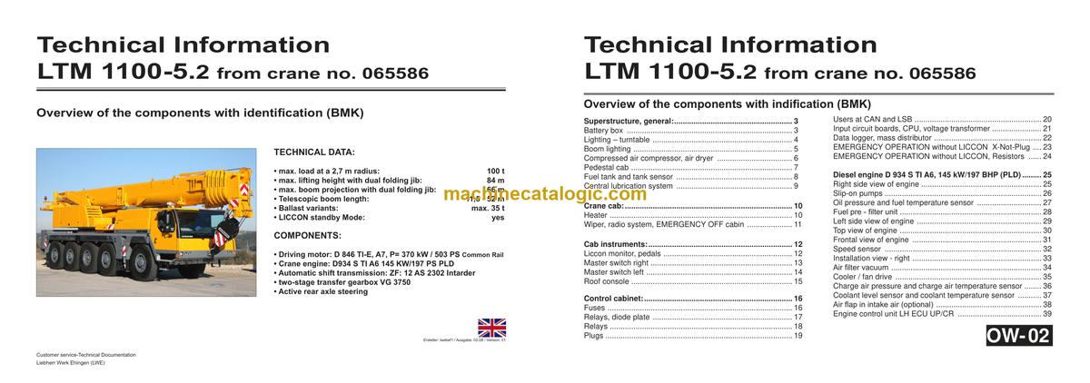
- Superstructure, general:
- Battery box
- Lighting – turntable
- Boom lighting
- Compressed air compressor, air dryer
- Pedestal cab
- Fuel tank and tank sensor
- Central lubrication system
- Crane cab:
- Heater
- Wiper, radio system, EMERGENCY OFF cabin
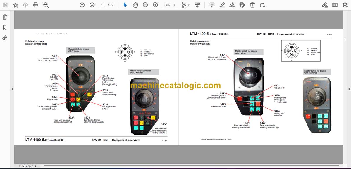
- Cab instruments:
- Liccon monitor, pedals
- Master switch right
- Master switch left
- Roof console
- Control cabinet:
- Fuses
- Relays, diode plate
- Relays
- Plugs
- Users at CAN and LSB
- Input circuit boards, CPU, voltage transformer
- Data logger, mass distributor
- EMERGENCY OPERATION without LICCON X-Not-Plug
- EMERGENCY OPERATION without LICCON, Resistors
- Diesel engine D 934 S TI A6, 145 kW/197 BHP (PLD)
- Right side view of engine
- Slip-on pumps
- Oil pressure and fuel temperature sensor
- Fuel pre – filter unit
- Left side view of engine
- Top view of engine
- Frontal view of engine
- Speed sensor
- Installation view – right
- Air filter vacuum
- Cooler / fan drive
- Charge air pressure and charge air temperature sensor
- Coolant level sensor and coolant temperature sensor
- Air flap in intake air (optional)
- Engine control unit LH ECU UP/CR
- Crane hydraulics:
- Overview hydraulic pumps
- Main control block without hoist gear 2
- Main control block – pressure stages, pressure sensors
- Oil cooler hydraulic oil, temperatur sensor
- Pressure switch monitoring winch 2
- Hoist gear I
- Hoist gear 2*
- Luffing gear
- Emergency operation LMB by-pass EN13000
- Slewing gear
- Auxiliary loads, turntable lock
- Ballasting
- Boom direction
- Telescopic boom:
- Cable drum, angle and length sensors
- Boom head
- Telescopic section pinning
- Gripper pinning, position sensor
- Emergency operation – tele pinning, gripper pinning
- Auxiliary equipment dual folding jib*:
- Control
- Hydraulic components, angle sensor
- Limit switch
- pecial equipment*
- Auxiliary heater
- Air conditioning
- Index
- Tourelle général:
- Caisson à batteries
- Eclairage dispositif de rotation tourelle
- Eclairage flèche télescopique
- Compresseur d‘air, dessiccateur d‘air
- Marchepied cabine tourelle
- Réservoir à carburant et capteur du réservoir
- Dispositif de graissage central
- Cabine de grue:
- Chauffage
- Moteur d‘essuie-glace, radio, ARRET D‘URGENCE cabine de grue
- Equipements cabine de grue:
- Moniteur Liccon, pédales
- Manipulateur droit
- Manipulateur gauche
- Console de toit
- Armoire électrique
- Fusibles
- Relais, platine à diodes
- Relais
- Connecteurs
- Participants CAN et LSB
- Platines d‘entrée, unité centrale, convertisseur de tension
- Enregistreur de données, distribution de la masse
- MODE D‘URGENCE sans LICCON – connecteurs X-Not
- MODE D‘URGENCE sans LICCON – résistances
- Moteur Diesel D 934 S TI A6, 145 kW/197 PS (PLD)
- Vue de droite du moteur
- Pompes-injecteur
- Capteur de pression d‘huile et capteur de température carburant
- Unité de préfiltrage du carburant
- Vue de gauche du moteur
- Vue de dessus du moteur
- Vue de devant du moteur
- Capteurs de vitesse de rotation
- Vue de droite en état monté
- Filtre d‘air en dépression
- Entraînement ventilateur refroidisseur
- Capteur de pression et de temp. air de suralimentation
- Capteur de niveau et de température du réfrigérant
- Clapet à air dans conduite d‘aspiration (option)
- Appareil de commande moteur LH ECU UP/CR
- Partie hydraulique tourelle:
- Vue d‘ensemble des pompes hydrauliques
- Bloc de commande principal avec dispositif de levage 2
- Bloc de commande principal – paliers de pression, capteurs de pression
- Refroidisseur d‘huile hydraulique, capteur de température
- Interrupteur à pression, contrôle du treuil 2
- Dispositif de levage 1
- Dispositif de levage 2*
- Dispositif de relevage de flèche
- Mode d‘urgence shintage CEC EN13000
- Dispositif de rotation tourelle
- Consommateurs auxiliaires, arrêt en rotation tourelle
- Système de contrepoids – côte gauche
- Orientation flèche télescopique*
- Flèche télescopique:
- Tambour à câble, capteur d‘angle et de longueur
- Tête de flèche
- Verrouillage éléments flèche télescopique
- Verrouillage pince, capteurs de position
- Mode d‘urgence verrouillage éléments flèche télescopique, verrouillage pince
- Equipements additionnels fléchette pliante double*:
- Commande
- Composants hydrauliques, capteur d‘angle
- Capteurs de fin de course
- Equipements spéciaux*
- Chauffage additionnel
- Climatisation
- Index
- Superestructura general:
- Caja de baterías
- Iluminación plataforma giratoria
- Iluminación pluma
- Compresor de aire, secador de aire
- Descansillo cabina
- Depósito de combustible y transmisor de depósito
- Lubricación centralizada
- Cabina de grúa:
- Calefacción
- Motor de limpiaparabrisas, equipo de radio, PARADA DE EMERGENCIA cabina
- Instrumentos cabina:
- Monitor Liccon, pedales
- Contróler derecha
- Contróler izquierda
- Consola de techo
- Armario de distribución
- Fusibles
- Relés, placa de diodos
- Relés
- Clavijas
- Usuarios de CAN y LSB
- Placas de entrada, unidad central, transformador de tensión
- Registrador de datos, distribución de masa
- SERVICIO DE EMERGENCIA sin LICCON – clavijas de emergencia X
- SERVICIO DE EMERGENCIA sin LICCON – resistencias
- Motor Diesel D 934 S TI A6, 145 kW/197 CV (PLD)
- Vista del motor derecha
- Bombas enchufables
- Transductor de presión de aceite y transmisor de temperatura de combustible
- Unidad filtrante previa de combustible
- Vista del motor izquierda
- Vista del motor arriba
- Vista del motor delante
- Transmisores de revoluciones
- Vista de montaje derecha
- Presión negativa del filtro de aire
- Radiador-accionamiento de ventilador
- Transductor de presión y transmisor de temperatura de aire de sobrealimentación
- Transmisor de nivel y transmisor de temperatura de refrigerante
- Válvula de aire en aire aspirado (opcional)
- Motor-aparato de mando LH ECU UP/CR
- Sistema hidráulico de plataforma giratoria:
- Sinopsis de bombas hidráulicas
- Bloque de mando principal con mecanismo de elevación 2
- Bloque de mando principal – etapas de presión, transductores de presión
- Radiador de aceite-aceite hidráulico, transmisor de temperatura
- Presostato control cabrestante 2
- Mecanismo de elevación 1
- Mecanismo de elevación 1
- Mecanismo de elevación 2*
- Mecanismo de elevación 2*
- Mecanismo de basculamiento
- Servicio de emergencia LMB puenteado EN13000
- Mecanismo de giro
- Mecanismo de giro
- Consumidores auxiliares, inmovilización de plataforma giratoria
- Contrapesos
- Contrapesos
- Dirección de pluma*
- Pluma telescópica:
- Tambores de cable, transductores angulares y transmisores de longitud
- Cabeza de pluma
- Embulonamiento de tramos telescópicos
- Embulonamiento de pinza, transductores de posición
- Servicio de emergenciaembulonamiento detramo telescópicoembulonamiento de pinza
- Equipamiento adicional plumín lateral doble*:
- Activación
- Componentes hidraúlicos, Sensor de ángulo
- Interruptor final de carrera
- Equipamiento adicional*
- Calefacción adicional
- Aire acondicionado
- Índice
Liebherr Crane


