The Liebherr LTM 1650-8.1 Mobile Crane is a serious bit of kit, and when it’s down, nobody cares about theory — they just want it found and fixed. The BMK / Technical Information manual is what your electrical and hydraulic guys grab when a schematic says “K15” or “V23” and they need to know where that actually lives on the machine. Component identification is what keeps you from wasting an hour opening the wrong covers or chasing the wrong harness. I’ve seen more time lost from “where is it?” than from the actual repair.
What this manual helps you do
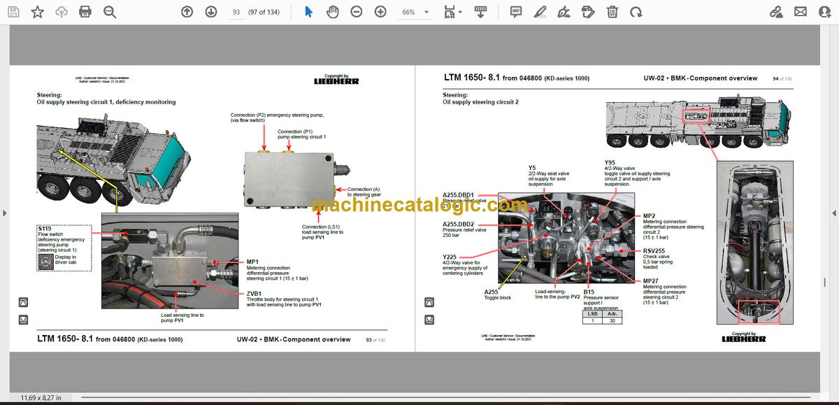
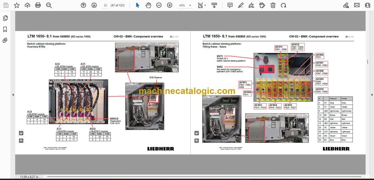
- Identify which physical component corresponds to a reference like E1, K3, or X45 on your wiring or hydraulic diagrams.
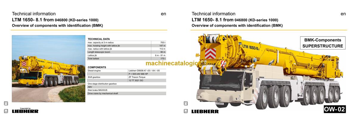
- Locate components on both carrier and superstructure using outline views and layout diagrams of the LTM 1650-8.1.
- Trace harnesses, valves, and sensors from schematic symbols to their real mounting positions on the crane.
- Cross-reference Liebherr component IDs to other documents you already have, like wiring diagrams or fault lists.
- Pinpoint what Liebherr actually calls a given box, sensor, or valve so you can talk correctly to parts or service.
Who this is for
This is aimed at workshop technicians, field service techs, electrical diagnostic engineers, fleet mechanics, and training instructors. If you’re after repair procedures, torque specs, fault trees, or part numbers, you need a service manual or parts catalogue instead, not this BMK.
FAQ
Q: Are the diagrams clear and searchable in the PDF?
A: These BMK PDFs are usually clean scans or native files with readable layouts; you can zoom in and search text like component IDs.
Q: Does it cover both the carrier and the upper crane?
A: Yes, this BMK manual is for carrier and superstructure together for SN 046884 of the LTM 1650-8.1.
Q: Does it work with other Liebherr documents?
A: Yes, the BMK is meant to be used alongside wiring diagrams, hydraulic schematics, parts catalogues, and service manuals by matching component IDs.
Bottom line: If your main problem is “where is this component on the crane?” then yes, this is exactly the document you need. If you want how-to repair steps or part numbers, then no, this isn’t the right book.
📘 Show Index
Table of Contents:
Superstructure — Table of Contents
- Superstructure general:
- Lighting slewing platform
- Working flood light slewing platform lateral
- Lighting boom
- LMB – warning device (EN 13000)
- Central greasing device
- Camera monitoring
- Transmission technology and slewing platform left
- Winches and slewing platform right
- Ballasting
- TY-suspension
- Transmission camera signal boom
- Crane cab:
- Heating – heating air conditioning
- Heating – additional heating Thermo Pro 90
- Heating – activation, temperature sensors
- Air-conditioner
- Wiper motor, washer pump
- Interior furnishing
- Transport position and operating position
- Fittings cab:
- LICCON-monitor, pedals
- Joystick 1, LSB-TE1 right
- Joystick 2, LSB-TE2 left
- Operation- and control unit
- Switch cabinet crane cab:
- Tilting frame – fuses
- Tilting frame – plug plate slewing platform
- Tilting frame – plug plate cab
- Relay, resistor modules
- Ventilation cab cabinet,
voltage converter
- Data logger II, remote diagnostics
- Ethernet Switch
- Diagnosis plug
- Switch cabinet slewing platform:
- LSB – plug-in boards ventilation switch cabinet
- Overview UEA modules
- Overview BTBs
- Tilting frame – fuses
- Release relay, voltage supply
- Relay, earth distribution
- EMERGENCY – socket
- EMERGENCY OPERATION – resistors
- Crane drive:
- Mechanical shaft
- Angle gear box
- Distribution gearbox
- Crane hydraulic:
- Overview hydraulic pumps
- Hydraulic oil tank
- Temperature sensor , oil filter and oil cooler
- Pressure stage valve
- Supply pressure
- Slewing gear
- Pump 12
- Activation, brake and slewing gear 1
- Slewing gear 2 and 3
- Slewing ring sensor
- Hoist gear
- Pump and pressure sensor
- Winch 1
- Winch 1* – connections
- Winch 2*
- Winch 2** – connections
- Winch 3*
- Winch 3* – ajustment pulley
- Winch 3* – connectors
- Luffing and telescoping
- Pump 7 and 8
- Control block
- Pressure sensor, release luffing down
- Lowering brake and boom boom steep
- Swivel joints
- Auxiliary consumer
- Pump
- Valve block
- Locking slewing platform, flow sensor ballast
- Tilting cab, cab arm slewing
- emergency operation
- Slewing gear
- Luffing gear
- Hoist gear
- Supply connections
- Counterweight frame
- Overview
- Electrical connections,
fitted sensors counterweight frame
- Hydraulic
- Supply connections
- Assembly winch
- Ballasting control block
- Ballasting cylinder
- Slewing cylinder counterweight receptacle
- Telescoping boom:
- Base section
- Behind connections
- Side wise attachments
- Boom head
- Telematic
- Position sensor, tele section pinning
- Cylinder pinning, toggle valve
- Emergency operation tele- / cylinder pinning
- Special equipment:
- Oil cooler 2*
- Immobiliser*
- Zoom – camera boom*
- Additional equipment:
- Tele- and luffing cylinder assembly/disassembly*
- Quick couplings boom
- Quick couplings luffing cylinder
- Activation pinning cylinder
- Pinning cylinder at the slewing platform
- Pinning cylinder at the boom
- Safety valve hydraulic
- TY-suspension*
- Overview*
- Hydraulic supply*
- Control block Ty-frame adjustment*
- Erection cylinder* and TY-frame steep*
- Adjustment cylinder* and angle sensor*
- Control block suspension functions*
- Control block suspension functions*
- Suspension winches*
- Suspension winches – tooth detection*
- Tension cylinder*
- Tension cylinder – sensors*
- Fixed jib*
- TF-adapter*
- Ty-adapter* – control block
- Luffing lattice jib*
- N-assembly unit*- angle sensor
- N-assembly unit* – sensors luffing jib up / down
- N-assembly unit*- fall back protection
- N-assembly unit* – A-frame 3
- NA-middle section*
- N-head section* and auxiliary jib*
- Index:
- Haftungsbegrenzung / Disclaimer
Liebherr Crane


