Format: PDF (Printable Document)
File Language: English
File Pages: 72
File Size: 2.75 MB (Speed Download Link)
Brand: Liebherr
Model: PR731C Crawler Loader
Type of Document: Operating Manual
$ 40
MACHINE DESCRIPTION
Diesel Engine
Splitter BOX
Hydraulic System
Main Frame, Steel Structure, Covers
Undercarri age
Operator’s Platform, Cab and Canopy
Attachments
TECHNICAL DATA PR 731 C
Dimensions – Basi c Machine
TRANSPORT DIMENSIONS AND WEIGHTS
Basic Machine
Operator’s Cab
Canopy
Track Cuard (1 piece)
Straight Blade
Push Arm – left With Hydr. Tilt Cylinder and Brace
Push Arm – right with Braces
Angle Blade w. Braces
“C” Frame
Single Shank Ripper
Multi Shank Ripper
Wi nch
Swinging Drawbar
Counterweight
GENERAL TECHNICAL DATA
Engine Installation
Engine Data
Air Cleaner
Coupling – Engine to Splitter box
Cooling System/Capacity
Fuel System f Capacity
Splitter box/Capacity
Hydraulic System
Closed Loop Hydrostatic Drive
Attachment Hydraulics
Control Val ve
Pilot (servo) Control Valve
Servo Pump
Hydraulic Tank
Hydraulic Oil Cooler
Hydraulic Oil Filters
Undercarriage
Travel Drive
Electrical System
Cab Heater/Fresh Air
Attachments
Bl ade Lift Cylinder
Blade Tilt Cylinder(Straight Blade)
Ripper Cylinder
Blade Tilt Cylinder (Angle Blade)
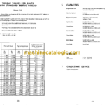
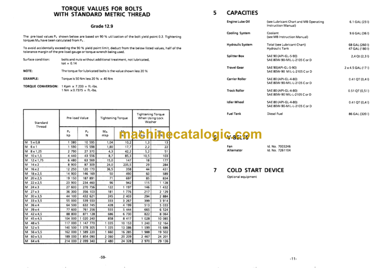
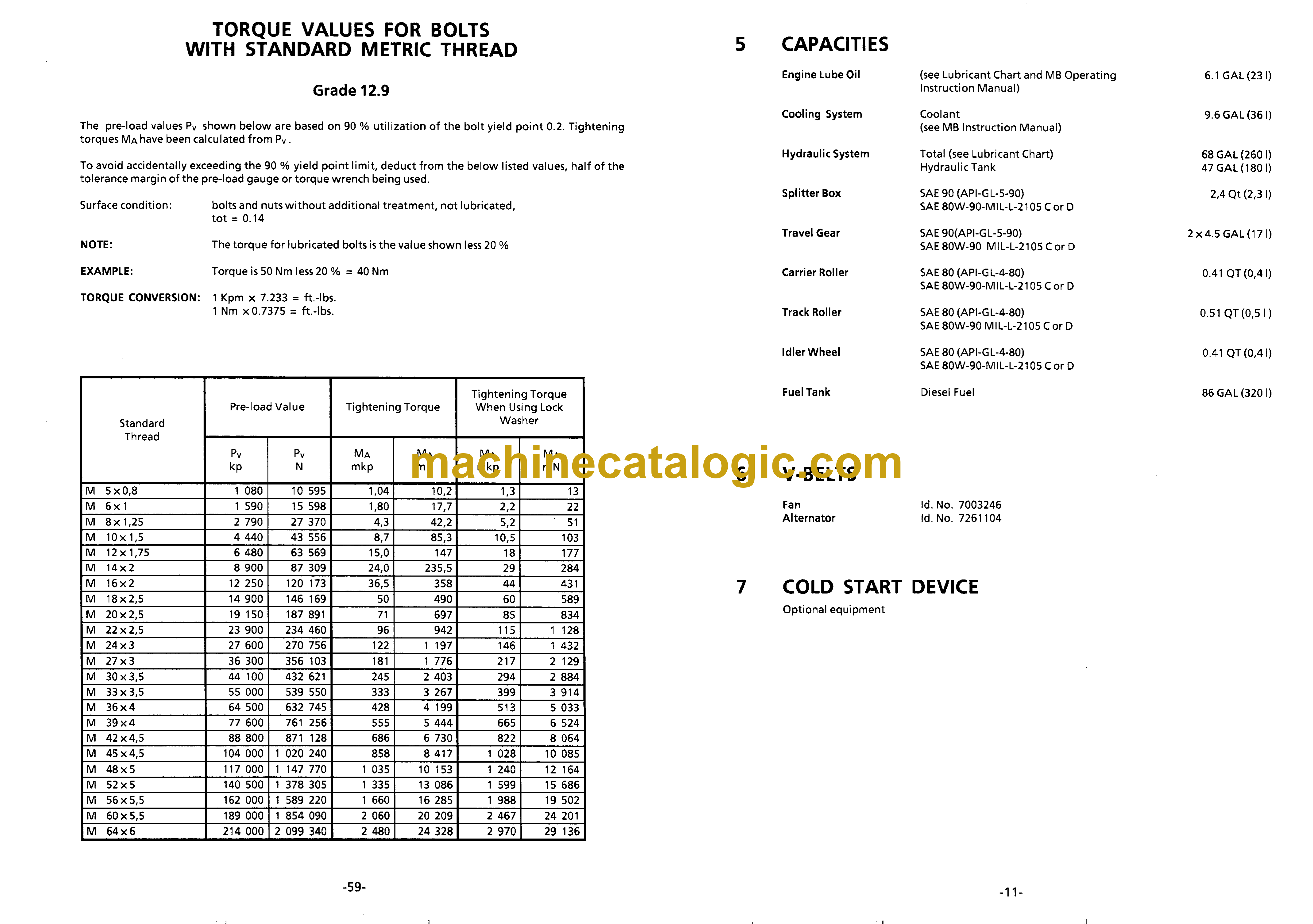
CAPACITIES
V-BELTS
COLD START DEVICE
FILTER ELEMENTS/ O-RINGS
Engine Filters
Hydraulic Filters
Cab Filters
O-Rings
SAFETY INFORMATION
Accident Preventi on
General Safety Information
Crushing and Burn Prevention
Fire and Explosion Prevention
Machine Start-up Safety
Engine Start-up and Operation Safety
Machine Operating Safety
Machine Towing and Pulling Safety
Machine Parking Safety
Machine Transportation Safety
BEFORE STARTING THE ENGINE
Check Engine Oil Level
Check Coolant Level
Check Electrical SystemlBattery
Check Fuel System/ Fuel Level
Check Air Filter/Vacuum Indicator
CONTROLS AND INSTRUMENTATION
O perator•s Cab
Operator’s Seat
Cab Heater/Fresh Air
OPERATION
Start-u p Procedures
Starting the Engine
Starting the Engine at LOW Ambient Temperatures with KBI Cold Start System
Low Idle Automatic – Ecomat
StoppingfParking the Machine
Travel Functions
Straight Travel
Counter Rotation
Turning left/right in forward or reverse
Turning Power Turn
Brake Operation
Hill-ow Travel Speed Selector
Towi ng
Attachment Operation
Blade – Raise/Lower
Blade – Float Position
Hydraulic Blade Tilt (Straight and Angle Blade)
Blade Pitch Adj ustment (Straight Bl ade)
Manual Adjustment of Angle Blade
Manual Tilt Adjustment of Angle Blade
Ripper Attachment Operation
Tilting the CabiCanopy
Raise (tilt) Cab
Lower Cab
MAINTENANCE
Diesel Engine
Engine Air Intake System
Servici ng the Air Cleaner
Dry Cleaning
Wet Cleaning
Pri mary Element Inspection
Pri mary Element Installation
Inspection Of the Air Intake and Pre-Cleaner
Fuel Tank/Hydraulic Tank
Fuel Filtermater Separator
Hydrau lic System
Check and Clean the Magnetic Rod
Replace Hydr. Tank Filter
Replace Servo Oil Filter
Replace Replenishing Oil (Spin on) and In •Line Filters on the Travel Pumps
Splitterbox
Hydraulic System Maintenance and Repair
Hydrau lic Cylind ers
Travel Gear
Travel Gear Maintenance
Travel Gear Parking Brake
Track Components
TO Tighten Track Tension
TO Release Track Tension
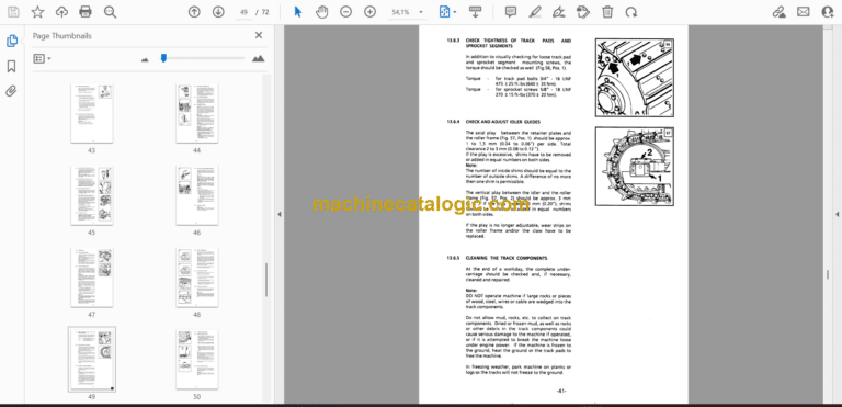
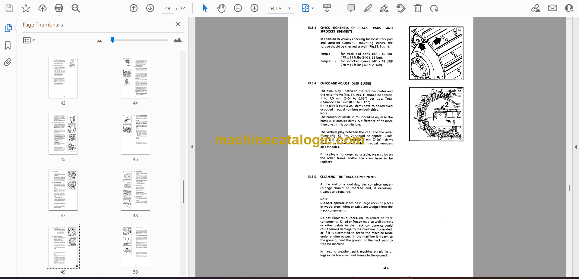
Check Tightness of Track Pads and Sprocket Segments
Check and Adjust the Idler Guides
Cleaning the Track Components
Replace Track Chain
Remove Sealed Track Chain
Install Sealed Track Chain
Remove SALT Chain
Install SALT Chain
Electrical System
Battery Maintenance
TO Replace Fuses
Heatingand Fresh Air System
Attachments
Cutting Edges and Corner Shanks
Blade Mounting, Push Arms and Braces
Ripper Shanks and Teeth
Repl acement of Wear and Tear Items
Piston Rod Preservation
MAINTENANCE GUIDELINES
Daily
Every 250 Operating Hours
Every 500 Operating Hours
Every 2000 Operati ng Hours
Lubri cation Chart
Lu bri cation Points
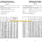
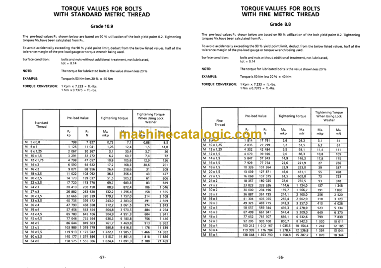
TORQUE CHART
ELECTRICAL SCHEMATIC

