Format: PDF (Printable Document)
File Language: English
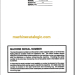
Brand: Link Belt Crane
Model: UC98A
Type of Document: Service Manual
$ 55
Front Axle Disassernbly
Front Brake Actuator
Front Brake Assembly
Front And Rear Suspen-
Sion
Troubleshooting Steering
System
Steer Cyl inder & Lines
Transmission Assembly
Transmission Controls
Drive Shafts
Bevel Gear (Overdrive)
Transmission
Rear Brake Actuator
Rear Axles & Brakes
Rear Axle Assembly
Troubleshooting Air
Brakes
Air Brake System
Hydraulic Outrigger
Trouble Shooting
Hydraulic Outrigger
System
Outrigger Holding Valve
Outrigger Beam & Box
Assembly
Telescoping Tube
Assernbly
Outrigger Jack. Cylinder
Outrigger Control Valve
Rotating Joint
Tire And Wheel Assembly
Area I
– Rubber Tire
Lower Frame, General
Front Axle And Wheel
Assembly
Area 3 – Upper Revolving Frame And Machinery
Undecking Machine
Conical Rollers
Swing Lock Control
Retractable Gantry
Area 4 — Vertical Shafts
General , Vertical Travel Shaft
Vertical Center Drive-
Shaft
Swing Center Drive-Shaft
Vertical Swing Shaft
Swing Brake Shaft
Swing Brake Assembly
Swing Brake Controls
Swing And Travel
Shifters
Area 5- Horizontal Shafts
Horizontal Shafts
(Geno)
Ind. Travel Reverse
Shaft
Ind. Swing Reverse
S ha ft
Reduction Shaft
Front Drum Shaft
F.D. And R.D. Brakes
Rear Drum Shaft
Boom Hoist Shaft
(Ind. Machines)
Boom Hoist Brake
Clutches (General)
Clutch Assembly
Clutch Rotating Joint
Area 6 – Upper Engine
Engine Wiring
Chain Case
Area 7 –
Speed-o-Matic Hydraulic Control System
S-0-M General
Trouble Shooting
Unloading Valve
Accumulator
External Check Valve
Rel ief Valve
S-o-M Filter
Rel ief Valve
S-o-M Pump
Control Valves & Stand
Area 9 – Tubular Boom Attachment
Live Mast And Cylinder
