A load moment indicator monitors how heavily a crane is loaded and keeps the operator inside safe limits. When the DS 150 starts giving bad readings or won't pass a check, downtime follows. A service manual is what a fleet mechanic or independent shop reaches for when they're repairing the unit in-house, replacing a board or transducer, or tracing a fault on a machine that came in without paperwork.
What this manual helps you do
- Trace the DS 150 connections, wiring diagram and digital inputs when a signal goes missing.
- Check the basic adjustments after repair or replacement.
- Replace the main board and transducer by following the DS 150 replacement procedure.
- Read the circuit drawings and central unit P.C. board layout to locate components on the board.
- Follow the electrical diagrams to isolate a problem before you swap parts.
Who this is for
Crane service technicians and rental fleet mechanics who maintain DS 150 systems on their own cranes. It also suits independent repair shops and dealer technicians who need workshop-level procedures for the unit.
FAQ
Q: What do I receive and how is it organised?
A: You get the set: 3 PDF files, 298 pages in total, in English. The files are Publication 031-300-100-753 (53 pages), Publication 031-300-190-052 (57 pages) and Manual 3 (188 pages), which is the main manual.
Q: Which machine does it fit?
A: It covers the PAT DS 150 load moment indicator. The title reads "PAT LMI Manual for DS350/GW and DS150", so the DS150 sections sit alongside DS350G/GW material in the same document.
Q: How does it fit the job I'm doing?
A: The sections include mechanical description, definitions, basic adjustments and checks, and DS150 sections for wiring, circuit drawings, board layout and main board and transducer replacement. That's the material you'd expect to work from when repairing the unit at your own shop.
Keep the full set on file and you've got the wiring, adjustment and replacement references ready the next time a DS 150 comes into the shop.
Click here to view the preview (PDF)
📘 Show Index
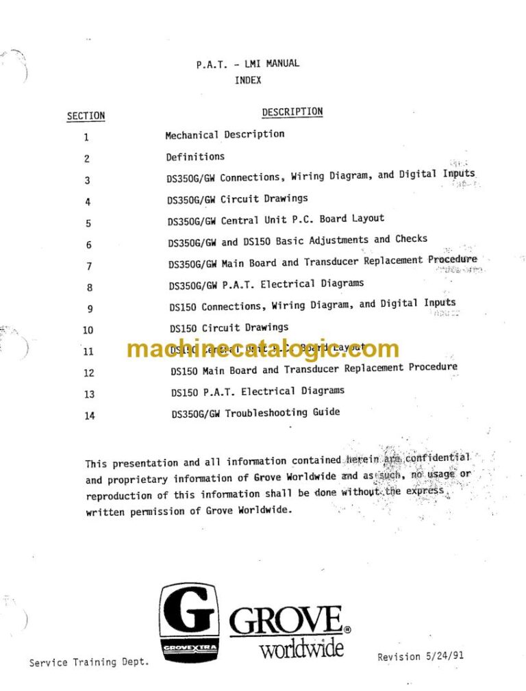
Table of Contents:
- Manual 3 (188 pages)
- Mechanical Description
- Definitions
- DS350G/GW Connections, Wiring Diagram, and Digital Inputs
- DS350G/GW Circuit Drawings
- DS350G/GW Central Unit P.C. Board Layout
- DS350G/GW and DS150 Basic Adjustments and Checks
- DS350G/GW Main Board and Transducer Replacement Procedure
- DS350G/GW P.A.T. Electrical Diagrams
- DS150 Connections, Wiring Diagram, and Digital Inputs
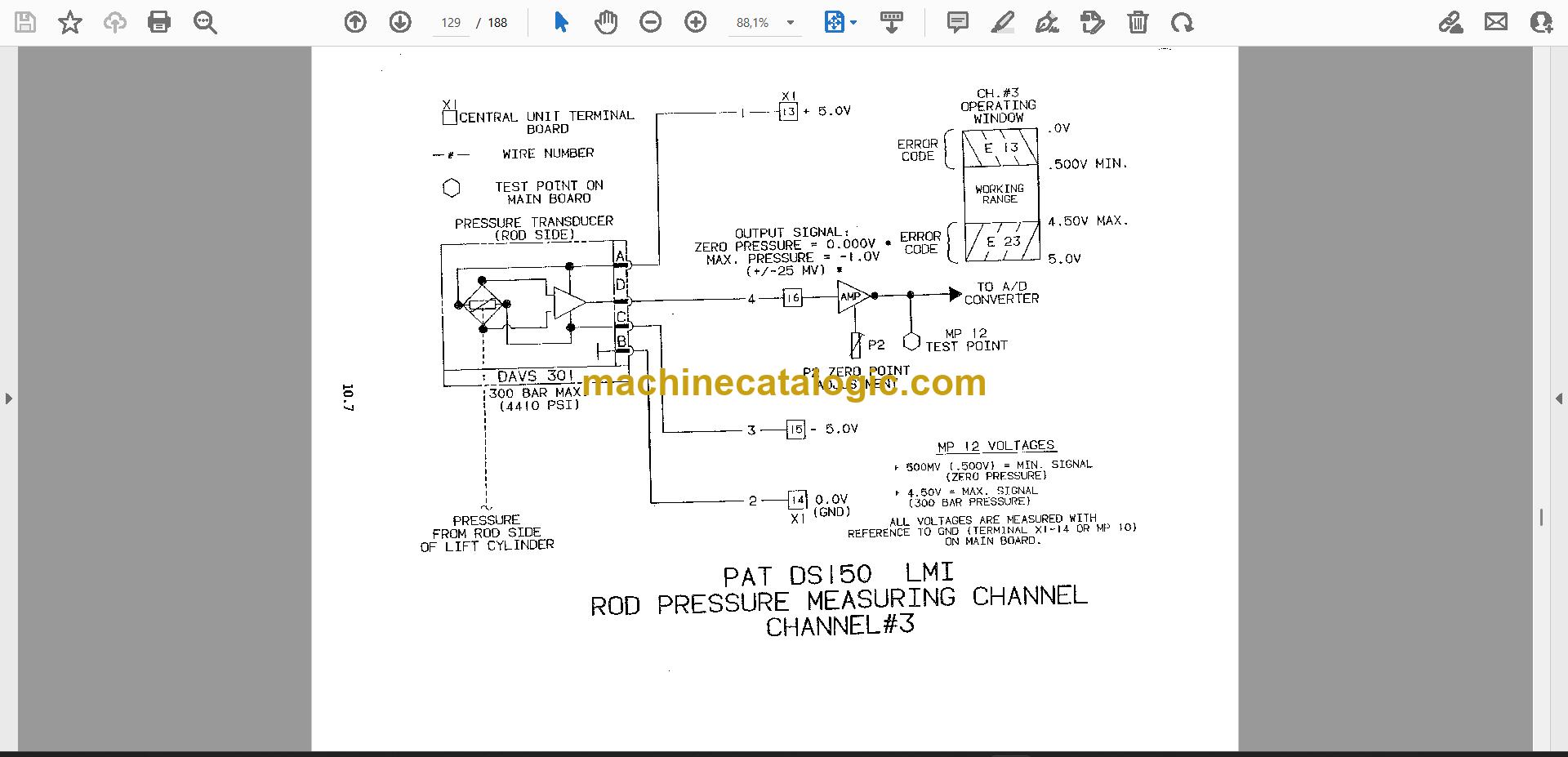
- DS150 Circuit Drawings
- DS150 Central Unit P.C. Board Layout
- DS150 Main Board and Transducer Replacement Procedure
- DS150 P.A.T. Electrical Diagrams
- DS350G/GW Troubleshooting Guide
- Publication 031-300-100-753 (53 pages)
- MECHANICAL DESCRIPTION OF THE SYSTEM COMPONENTS
- MECHANICAL AND ELECTRICAL DESCRIPTION OF THE CENTRAL UNIT
- BASIC SYSTEM COMPONENT LAYOUT
- BASIC ADJUSTMENT OF THE COMPONENTS
- DEFINITIONS
- DRAWINGS
- SYSTEM ELECTRICAL DIAGRAM
- CENTRAL UNIT BOARD LAYOUT AND MEASURING POINTS 024-150-300-001
- PROCEDURE
- EPROM REPLACEMENT IN CENTRAL UNIT
- PISTON & ROD PRESSURE CHANNEL ZERO POINT ADJUSTMENT
- LENGTH & ANGLE ADJUSTMENTS
- THEORY
- ANTI-TWO BLOCK & SHUTOFF CIRCUIT
- LENGTH MEASURING CHANNEL
- PISTON SIDE PRESSURE MEASURING CHANNEL
- TROUBLESHOOTING FLOW CHARTS
- GENERAL FLOWCHART
- LEVER LOCKOUT ACTIVATED
- BROKEN LENGTH CABLE
- ERROR CODE TABLE
- ADDENDUM A BASIC ADJUSTMENT AND VOLTAGE CHECKS
- Publication 031-300-190-052 (57 pages)
- MECHANICAL DESCRIPTION OF THE SYSTEM COMPONENTS
- MECHANICAL AND ELECTRICAL DESCRIPTION OF THE CENTRAL UNIT
- BASIC ADJUSTMENT OF THE HARDWARE
- DEFINITIONS
- DRAWINGS
- DRAWING 4. CENTRAL UNIT ELECTRICAL DIAGRAM
- DRAWING 5. CABLE REEL ELECTRICAL DIAGRAM
- DRAWING 6. CENTRAL UNIT BOARD LAYOUT AND MEASURING POINTS
- PROCEDURE
- PPRCEDURE 1. EPROM REPLACEMENT IN CENTRAL UNIT
- PROCEDURE 2. PISTON & ROD PRESSURE CHANNEL ZERO POINT ADJUSTMENT
- PROCEDURE 3. LENGTH & ANGLE ADJUSTMENTS
- THEORY
- THEORY 1. ANTI-TWO BLOCK & SHUTOFF CIRCUIT
- THEORY 2. LENGTH MEASURING CHANNEL
- THEORY 3. PISTON SIDE PRESSURE MEASURING CHANNEL
- TROUBLESHOOTING FLOW CHARTS
- GENERAL FLOWCHART
- LEVER LOCKOUT ACTIVATED
- BROKEN LENGTH CABLE
- ERROR CODE TABLE
- ADDENDUM A BASIC ADJUSTMENT AND VOLTAGE CHECKS
PAT PDF Manuals
All Crane Manuals