Format: PDF (Printable Document)
File Language: English
File Pages: 57
File Size: 925.06 KB (Speed Download Link)
File Count: 1 PDF file
Brand: PAT
Model: DS 150
Equipment Type: Load Moment Indicator
Book No: 9333104092
Type of Document: Service Manual
Searchable: Yes, text is searchable and copyable
Delivery: Instant download after payment
$ 55
A load moment indicator (LMI) monitors crane loading, and the DS150C is the unit used on Grove machines. When it throws a fault, reads wrong or needs replacing, the service manual is what a technician opens. Crane service techs and fleet mechanics use it to check the system, set it up and fix it in-house.
What this manual helps you do
Who this is for
A crane service technician or rental fleet mechanic who has a Grove crane with a DS150C LMI that needs diagnosis or adjustment. Also useful to an independent repair shop or dealer technician who inherited a machine with no paperwork.
FAQ
Q: What do I receive and how is it organised?
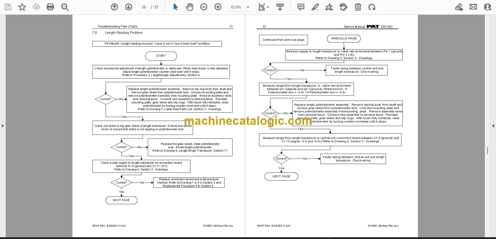
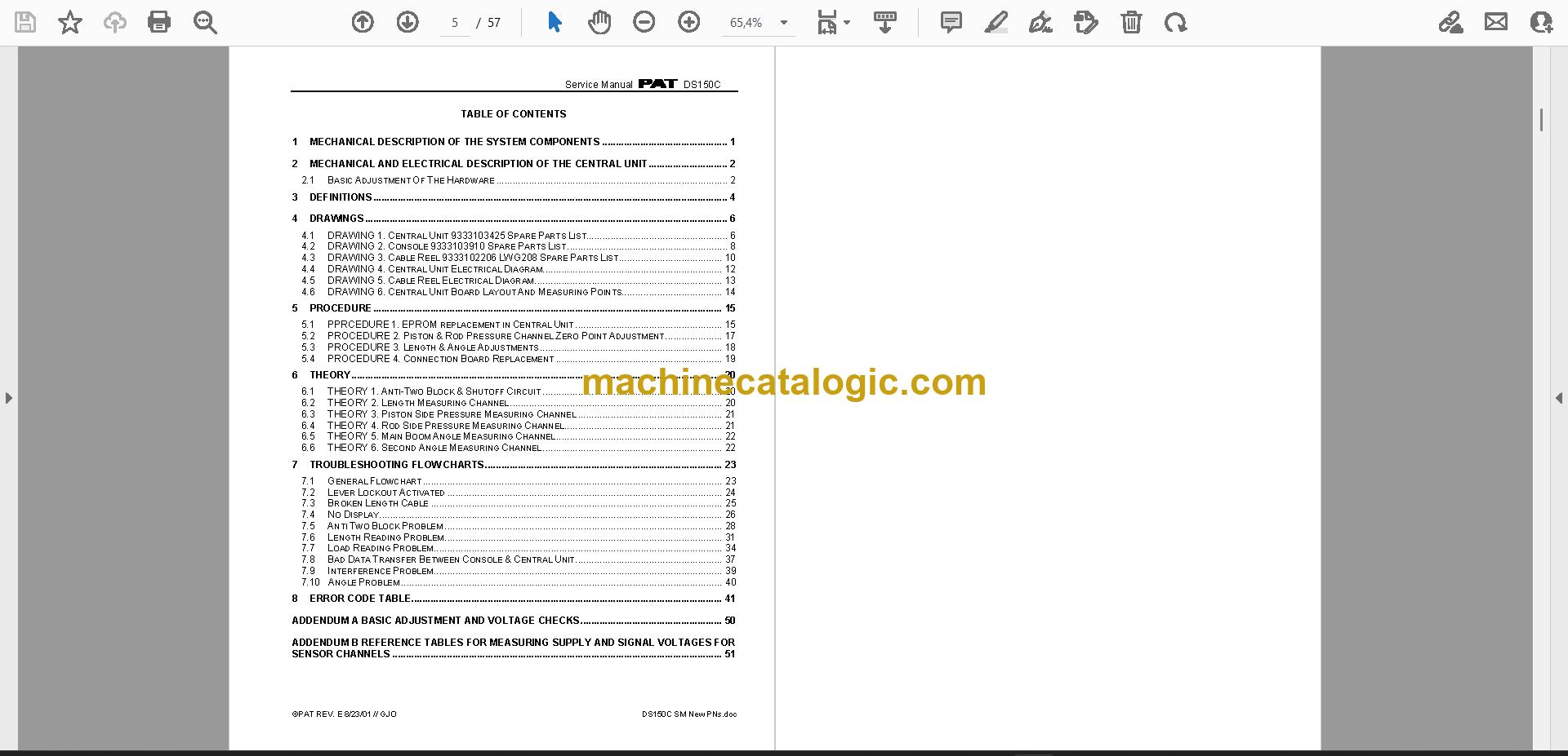
A: You get 1 PDF file of 57 pages in English, with a text layer you can search and copy. It is the complete manual, and the sections include definitions, theory, drawings, procedure, troubleshooting flow charts, the error code table and Addendum A.
Q: Which machine and component does it fit?
A: It is the PAT DS150C Load Moment Indicator Service Manual, publication number 9333104092, from the Grove machine documentation. It is used on Grove machines.
Q: How does it fit the job I'm doing?
A: If you're chasing a fault code, checking voltages or setting up the unit, the flow charts, error code table and Addendum A are laid out for that. Search the PDF for a code or term and go straight to the entry.
Keep it open on the bench or the laptop and work through the fault from the code to the fix.
Click here to view the preview (PDF)