Format: PDF (Printable Document)
File Language: English
File Pages: 482
File Size: 37.41 MB (Speed Download Link)
Brand: Sumitomo
Model: SH135X-3B
Type of Document: Service Text & Troubleshooting Manual & Shop Manual
$ 45
About This Shop Manual
Safety ……………………………………………………………………………………………………………..1
Introduction……………………………………………………………………………………………………..2
Using Technical Information …………………………………………………………………………….3
Symbols……………………………………………………………………………………………………….3
Precautions for Use…………………………………………………………………………………………4
General Preparation for Disassembly ……………………………………………………………..15
General Cautions for Assembly ……………………………………………………………………..17
General Cautions When Performing Inspections………………………………………………21
Tightening Torque
Tightening Bolts and Nuts …………………………………………………………………………….22
Retightening Torque Table…………………………………………………………………………….22
Numerical Conversion Table ………………………………………………………………………….23
Specifications
Overall View ………………………………………………………………………………………….. 1
Equipment Layout………………………………………………………………………………………….1
Overall……………………………………………………………………………………………………..1
Operator’s Seat …………………………………………………………………………………………2
Main Equipment Table…………………………………………………………………………….. 3
Lower Assembly Diagram (overall) …………………………………………………………………..3
1. SH135X-3B (mono-boom with blade/offset-boom with blade)……………………..3
Lower Component …………………………………………………………………………………………4
1. Travel Unit……………………………………………………………………………………………4
2. Take-up Roller ……………………………………………………………………………………..4
3. Upper Roller ………………………………………………………………………………………..4
4. Lower Roller ………………………………………………………………………………………..4
5. Recoil Spring……………………………………………………………………………………….5
6. Shoe …………………………………………………………………………………………………..5
Upper Component …………………………………………………………………………………………6
1. Swing Unit …………………………………………………………………………………………..6
Engine-related ………………………………………………………………………………………………7
1. Engine ………………………………………………………………………………………………..7
2. Muffler ………………………………………………………………………………………………..8
3. Air Cleaner (double element)………………………………………………………………….8
4. Radiator………………………………………………………………………………………………8
5. Fuel Tank…………………………………………………………………………………………….9
6. Hydraulic Oil Tank……………………………………………………………………………….11
Table of Contents
Hydraulic Device………………………………………………………………………………………….13
1. Hydraulic Pump ………………………………………………………………………………….13
Control-related…………………………………………………………………………………………….14
1. Control Valve ……………………………………………………………………………………..14
2. Solenoid Valve (3 stack) ………………………………………………………………………15
3. Remote Control Valve………………………………………………………………………….16
4. Remote Control Valve Characteristic Diagram………………………………………..18
5. Cushion Valve (with heat circuit) …………………………………………………………..20
6. Center Joint ……………………………………………………………………………………….20
Backhoe Attachment…………………………………………………………………………………….21
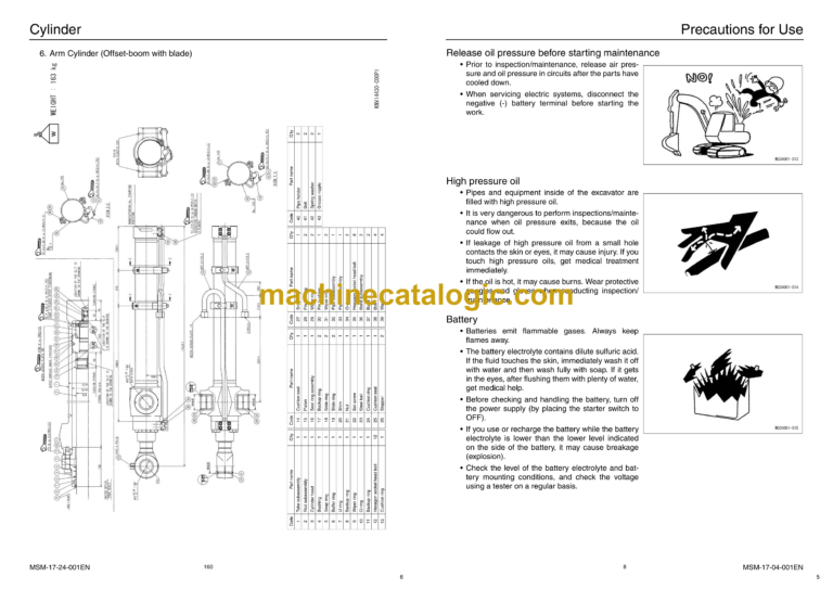
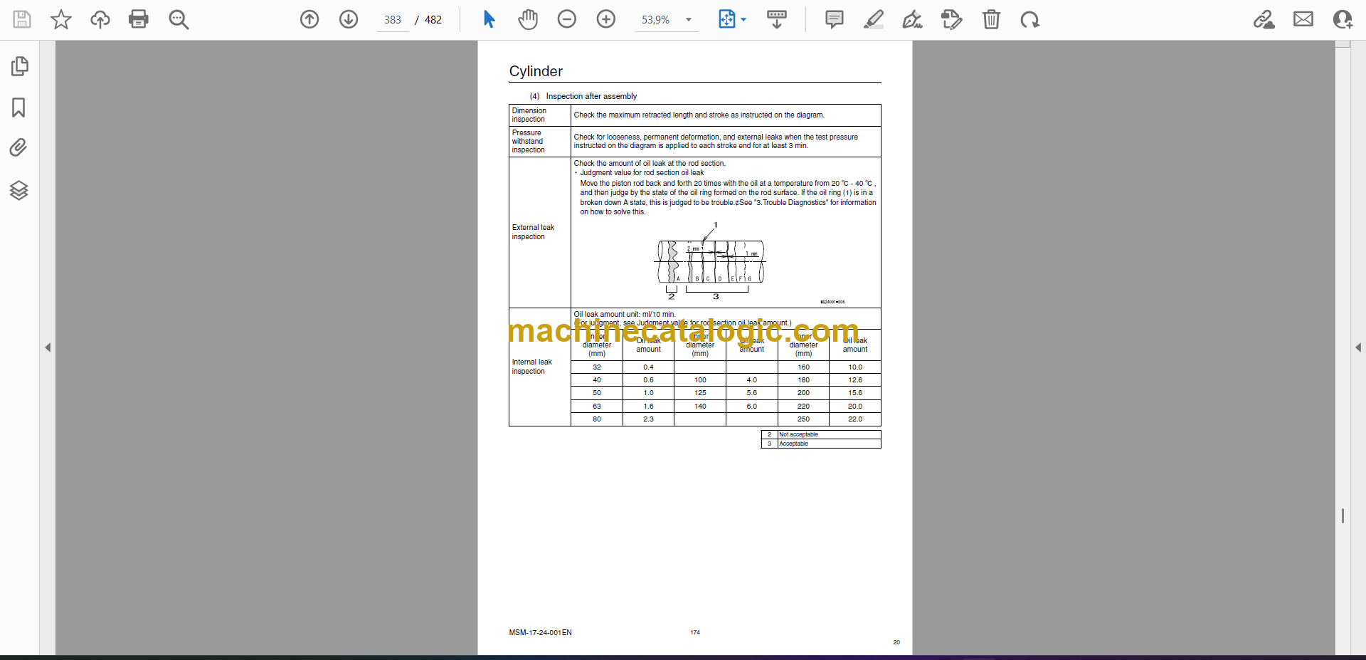
1. Cylinder …………………………………………………………………………………………….21
2. Attachments ………………………………………………………………………………………23
Oil and Filters ………………………………………………………………………………………. 24
Method of Use for Fuel and Lubricating Oil According to Air Temperature……………24
Fuel and Oil…………………………………………………………………………………………….24
Anti-freeze………………………………………………………………………………………………24
Sumitomo Genuine Parts………………………………………………………………………………24
Engine Fuel and Filter Maintenance……………………………………………………………….25
1. Fuel Used ………………………………………………………………………………………….25
2. Filter and Maintenance………………………………………………………………………..26
Consumable Parts ……………………………………………………………………………………….27
SH135X-3B Oil Feeding and Element Replacement …………………………………………28
Replacement Times for Hydraulic Oil and Filters When Using the Breaker ………….31
Performances
Lifting Capacity………………………………………………………………………………………. 1
Precautions for Lifting Loads with the Hydraulic Excavator ………………………………….1
Lifting Capacities SH135X-3B (Mono-boom with blade)………………………………………2
1. Standard Arm (2.39 m), 500 Grouser shoe (Blade down)…………………………..2
2. Standard Arm (2.39 m), 500 Grouser shoe (Blade up) ………………………………3
3. Long Arm (2.85 m), 500 Grouser shoe (Blade down) ………………………………..4
4. Long Arm (2.85 m), 500 Grouser shoe (Blade up) …………………………………….5
Lifting Capacities SH135X-3B (Offset-boom with blade) ……………………………………..6
1. Standard Arm (2.11 m), 500 Grouser shoe (Blade down)…………………………..6
2. Standard Arm (2.11 m), 500 Grouser shoe (Blade up) ………………………………7
3. Long Arm (2.41 m), 500 Grouser shoe (Blade down) ………………………………..8
4. Long Arm (2.41 m), 500 Grouser shoe (Blade up) …………………………………….9
Hydraulic Pump Control Diagram……………………………………………………………. 10
P-Q Diagram……………………………………………………………………………………………….10
2
Table of Contents
3 MSM-17-00-001EN
Disassembling and Maintenance Instructions for Main Body
Maintenance Procedures
Lower Unit Path Block Diagram……………………………………………………………………….1
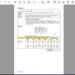
Main Parts Tightening Torque………………………………………………………………………….2
Bolt and Nut Tightening ……………………………………………………………………………..2
Inspection and Maintenance……………………………………………………………………………3
Retightening Torque Table ………………………………………………………………………….3
Lower Unit
Track Shoe……………………………………………………………………………………………………7
1. Removal Procedure………………………………………………………………………………8
2. Installation Procedure……………………………………………………………………………9
3. Track Link Replacement Procedure……………………………………………………….10
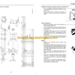
Travel Unit …………………………………………………………………………………………………..11
1. Cautions for Assembly…………………………………………………………………………11
2. Removal Procedure…………………………………………………………………………….12
3. Installation procedure ………………………………………………………………………….13
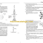
Recoil Spring ………………………………………………………………………………………………14
1. Removal Procedure…………………………………………………………………………….15
2. Installation Procedure………………………………………………………………………….16
Upper Roller ……………………………………………………………………………………………….17
1. Removal Procedure…………………………………………………………………………….18
2. Installation Procedure………………………………………………………………………….19
Lower Roller………………………………………………………………………………………………..20
1. Removal Procedure…………………………………………………………………………….21
2. Installation Procedure………………………………………………………………………….22
Center Joint ………………………………………………………………………………………………..23
1. Removal Procedure…………………………………………………………………………….24
2. Installation Procedure………………………………………………………………………….25
Upper Unit
Swing Unit ………………………………………………………………………………………………….26
Engine ……………………………………………………………………………………………………….30
Hydraulic Pump …………………………………………………………………………………………..33
Control Valve ………………………………………………………………………………………………35
Remote Control Valve…………………………………………………………………………………..36
Operator Cab………………………………………………………………………………………………39
Disassembling and Maintenance Instructions for Major Parts
Attachment (mono boom)
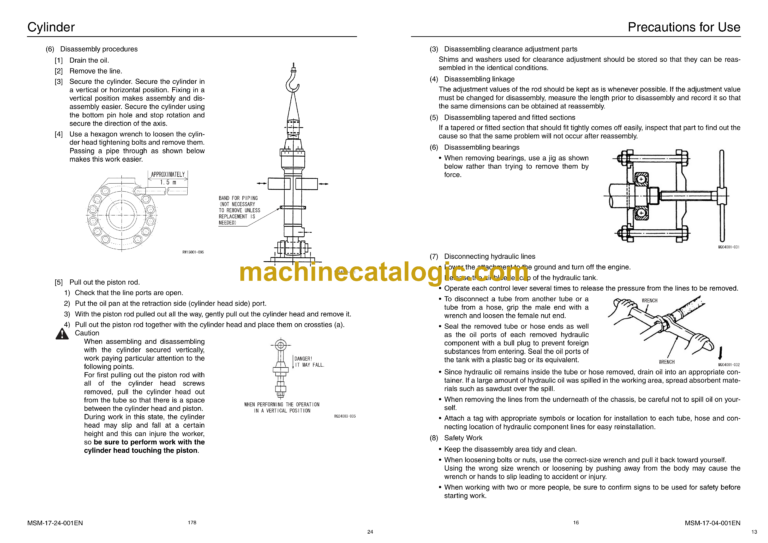
Removal and Installation of Bucket Cylinder ……………………………………………………..1
1. Removal Procedure………………………………………………………………………………1
2. Installation Procedure……………………………………………………………………………3
Removal and Installation of Arm Cylinder………………………………………………………….5
1. Removal Procedure………………………………………………………………………………5
2. Installation Procedure……………………………………………………………………………7
Removal and Installation of Boom Cylinder……………………………………………………….9
1. Removal Procedure………………………………………………………………………………9
2. Installation Procedure………………………………………………………………………….11
Attachment (offset boom)
Removal Procedure ……………………………………………………………………………………..14
1. Boom Cylinder……………………………………………………………………………………14
2. Offset Cylinder……………………………………………………………………………………14
3. Arm Cylinder………………………………………………………………………………………15
Installation of Cylinder ………………………………………………………………………………….16
Take-up Roller
Assembly and Disassembly Procedures …………………………………………………………17
1. Configuration Diagram…………………………………………………………………………17
2. Tools …………………………………………………………………………………………………17
3. Jig Dimension Diagram ……………………………………………………………………….17
4. Disassembly Procedures……………………………………………………………………..18
5. Assembly Procedures………………………………………………………………………….22
Assembly Diagram……………………………………………………………………………………….26
Upper Roller
Assembly and Disassembly Procedures …………………………………………………………27
1. Configuration Diagram…………………………………………………………………………27
2. Tools …………………………………………………………………………………………………27
3. Jig Dimension Diagram ……………………………………………………………………….27
4. Disassembly Procedures……………………………………………………………………..28
5. Assembly Procedures………………………………………………………………………….31
Assembly Diagram……………………………………………………………………………………….35
4
Table of Contents
5 MSM-17-00-001EN
Lower Roller
Assembly and Disassembly Procedures …………………………………………………………36
1. Configuration Diagram…………………………………………………………………………36
2. Tools …………………………………………………………………………………………………36
3. Jig Dimension Diagram ……………………………………………………………………….36
4. Disassembly Procedures……………………………………………………………………..37
5. Assembly Procedures………………………………………………………………………….40
Assembly Diagram……………………………………………………………………………………….44
Grease Cylinder
Assembly and Disassembly Procedures …………………………………………………………45
1. Configuration Diagram…………………………………………………………………………45
2. Tools and Jigs…………………………………………………………………………………….45
3. Disassembly Procedures……………………………………………………………………..46
4. Assembly Procedures………………………………………………………………………….47
Assembly Diagram……………………………………………………………………………………….49
Rotating Joint
Disassembling and Assembling Instructions ……………………………………………………50
1. Component Diagram …………………………………………………………………………..50
2. Tools and Jigs…………………………………………………………………………………….51
3. Disassembling Instructions…………………………………………………………………..52
4. Assembling Instructions ………………………………………………………………………54
Assembly Drawings ……………………………………………………………………………………..57
Air Conditioner
Disassembling Instructions……………………………………………………………………………58
1. Disassembling the Case………………………………………………………………………58
2. Replacing the Blower Motor …………………………………………………………………59
3. Replacing the Evaporator …………………………………………………………………….59
4. Replacing the expansion valve……………………………………………………………..60
5. Replacing the heater core ……………………………………………………………………60
6. Replacing the motor actuator ……………………………………………………………….60
Maintenance Standards
Check Sheet ……………………………………………………………………………………………….61
1. Drive Sprocket ……………………………………………………………………………………61
2. Take-up Roller ……………………………………………………………………………………62
3. Upper Roller ………………………………………………………………………………………63
4. Lower Roller ………………………………………………………………………………………64
5. Track Shoe (grouser shoe) …………………………………………………………………..65
6. Attachment (backhoe) …………………………………………………………………………66
7. Attachment (offset boom) …………………………………………………………………….75
8. Blade ………………………………………………………………………………………………..84
Inspection Gauge ………………………………………………………………………………………..87
1. For Drive Sprocket………………………………………………………………………………87
2. For Take-up Roller ………………………………………………………………………………87
3. For Upper Roller …………………………………………………………………………………88
4. For Lower Roller …………………………………………………………………………………88
List of Attachment Gap Adjustment Shims ………………………………………………………89
List of Attachment Gap Adjustment Shims (for boom foot)…………………………………93
6
Table of Contents
7 MSM-17-00-001EN
Disassembling and Maintenance Instructions for Major Hydraulic Components
Hydraulic Pump
Disassembly and Maintenance Procedures ………………………………………………………1
1. Procedures for Assembly and Disassembly of Pump Main Unit Section……….1
2. Pump Main Unit Section Maintenance Standards……………………………………10
3. Causes of Trouble and Solutions…………………………………………………………..12
4. Pump Breakdown Diagram…………………………………………………………………..14
5. Pump Structural Diagram…………………………………………………………………….15
Regulator Handling ………………………………………………………………………………………17
1. Summary …………………………………………………………………………………………..17
2. Operation Explanation…………………………………………………………………………18
3. Regulator Adjustment………………………………………………………………………….20
4. Causes and Solutions for Regulator Trouble …………………………………………..22
5. Table and Diagram ……………………………………………………………………………..23
Regulator Assembly and Disassembly Procedures…………………………………………..27
1. Caution for Disassembly………………………………………………………………………27
2. Tool …………………………………………………………………………………………………..27
3. Disassembly Procedures……………………………………………………………………..28
4. Assembly Procedures………………………………………………………………………….31
5. Regulator Assembly Structural Diagram (front side) ………………………………..34
6. Regulator Assembly Structural Diagram (rear side) …………………………………36
Procedures for Assembly and Disassembly of PTO Unit……………………………………38
1. Tool …………………………………………………………………………………………………..38
2. Disassembly Procedures……………………………………………………………………..38
3. Assembly procedures ………………………………………………………………………….41
PTO Unit Maintenance Standards ………………………………………………………………….44
1. Standards for replacing worn parts ……………………………………………………….44
2. Tightening torque ……………………………………………………………………………….44
Travel Unit
Assembly and Disassembly of Travel Motor …………………………………………………….47
1. Maintenance procedures……………………………………………………………………..47
2. Disassembly ………………………………………………………………………………………53
3. Maintenance standards ……………………………………………………………………….70
4. Assembly …………………………………………………………………………………………..72
5. Performance confirmation test………………………………………………………………89
6. 3-dimensional disassembly diagram of reduction gear section ………………….90
7. 3-dimensional disassembly diagram of hydraulic motor section…………………91