$ 0
0
$ 0
0

Tadano TR-500XL-4 Rough Terrain Crane Service Manual

Format: PDF (Printable Document)

File Language: English

File Pages: 1,425

File Size: 41.86 MB (Speed Download Link)

File Count: 6 PDF files

Brand: Tadano

Model: TR-500XL-4

Equipment Type: Rough Terrain Crane

Book No: SA01-01-2E

Manuals Included: 5 separate publications

Type of Document: Service Manual

Serial No. (manuals included): 540358 and up

Searchable: Yes, text is searchable and copyable

Delivery: Instant download after payment

Categories: ,

$ 55

Share:

Tadano TR-500XL-4 Rough Terrain Crane Service Manual

A rough terrain crane like the Tadano TR-500XL-4 works on uneven ground where a truck crane can't. It has a single cab, a telescopic boom and outriggers to set it up. When one comes into the shop with a hydraulic fault, a slow boom or a brake complaint, the technician needs the workshop procedures to fix it right.

What this manual helps you do

  • Troubleshoot the hydraulic system, working through the hydraulic system troubleshooting section.
  • Replace and rebuild components using the dismounting and remounting and disassembly and reassembly procedures.
  • Check and adjust settings with the data, adjusting and checks section.
  • Trace circuits with the system diagrams when a function stops working.
  • Verify the outrigger, swing, boom elevating, boom telescoping and winch systems after repair.

Who this is for

This is for the crane service technician, the rental fleet mechanic and the independent repair shop. It also suits a dealer technician or plant maintenance crew working on a TR-500XL-4 that's out of warranty or arrived with no paperwork.

FAQ

Q: What do I receive and how is it organised?

A: You get the full set: 6 PDF files, 1,425 pages in total, all in English. The download holds 5 separate manuals: SA01-01-2E (447 pages, the main manual), GR-500XL-1-S1(U)-1E for serial no. 540358 and up (327 pages), W301-0135E (163 pages), W303-0256E (224 pages) and W303-0257E (264 pages). The text is searchable and copyable.

Q: Which machine does it fit?

A: The Tadano TR-500XL-4 rough terrain crane. The main manual is titled "TR-500XL-4 Service Manual" and opens with General Repair Cautions.

Q: How does it fit my repair job?

A: It's workshop-level. Sections run by system, from hydraulic power generating, steering, brake and suspension to the control and safety systems, so you can go straight to the circuit you're working on and search for the term you need.

Pull the pump, rebuild the cylinder, chase the fault, and have the procedures open on the bench while you do it.

Click here to view the preview (PDF)

📘 Show Index

Table of Contents:

  • Publication SA01-01-2E (447 pages)
    • Safety
    • Foreword
    • (B) Hydraulic Power Generating System
    • (C) Outrigger System
    • (D) Swing System
    • (E) Boom Elevating System
    • (F) Winch System
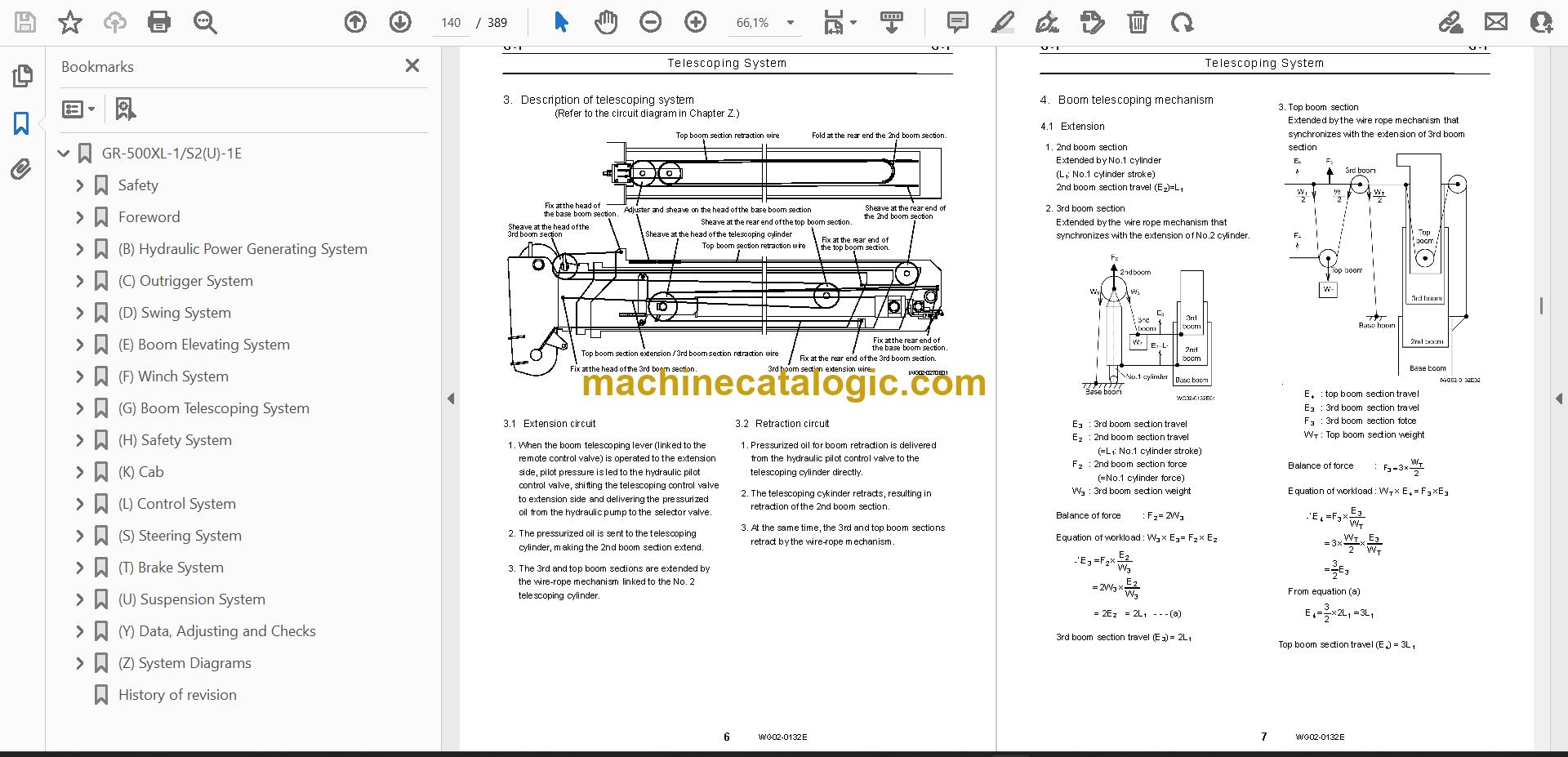
    • (G) Boom Telescoping System
    • (H) Safety System
    • (L) Control System
    • (S) Steering System
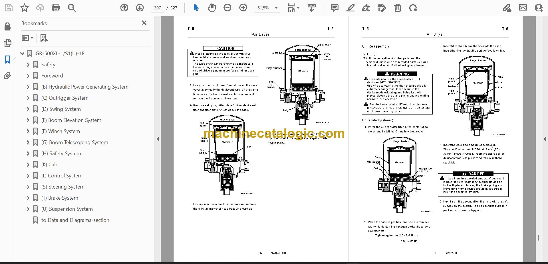
    • (T) Brake System
    • (U) Suspension System
    • (Y) Data, Adjusting and Checks
    • (Z) System Diagrams
    • History of revision
    • Contents of Information
    • Hydraulic System Troubleshooting
    • Dismounting and Remounting
    • Disassembly and Reassembly
    • Sealing Parts
    • Piping Procedure
    • Machine Elements
    • Hydraulic Oil
  • Publication GR-500XL-1-S1(U)-1E / Serial No. 540358 and up (327 pages)
    • Safety
      • 1.Fundamental cautions
      • 2.Cautions in working
      • 3.Cautions in operation
    • Foreword
      • 1.Applicable spec. NO
      • 2.Separate service manual
      • 3.Outline of specifications
    • (B) Hydraulic Power Generating System
      • B-1Hydraulic Power Generating System
      • B-2Hydraulic Pump (Double Variable Displacement Pump)
      • B-3Hydraulic Pump (Double Gear Pump)
    • (C) Outrigger System
      • C-1Outrigger System
      • C-2Jack Cylinder
      • C-3Pilot check Valve (Jack Cylinder Retracting Prevention)
    • (D) Swing System
      • D-1Swing System
      • D-2Swing Ass’y
      • D-3Hydraulic Pilot Control Valve (Swing)
    • (E) Boom Elevation System
      • E-1Elevating System
      • E-2Elevating Cylinder
      • E-3Counterbalance Valve (Elevating)
    • (F) Winch System
      • F-1Winch System
      • F-2Winch
      • F-3Hydraulic Motor (Winch)
    • (G) Boom Telescoping System
      • G-1Telescoping System
      • G-2Boom (Four-Section Boom)
      • G-3Jib
    • (H) Safety System
      • H-1Safety System
      • H-2Boom Length and Angle Detector
      • H-3Outrigger Extension Length Detector
    • (L) Control System
      • L-1Control System
      • L-2Remote Control Valve (Lever)
      • L-5Shuttle Valve (Lever
    • (S) Steering System
      • S-1Steering System
      • S-2Priority Valve
      • S-3Orbitrol
    • (T) Brake System
      • T-1Brake System
      • T-2Brake (Service Brake)
      • T-3Brake Valve
    • (U) Suspension System
      • U-1Suspension System
      • U-2Suspension Lock Cylinder
      • U-3Pilot Check Valve (Spring Lock Cylinder)
    • to Data and Diagrams-section
  • Publication W301-0135E (163 pages)
    • Foreword
      • Applicable spec. No
    • Components of the AML (AML-L C) Main Unit
      • Panel
      • Internal view and name plate
      • Internal block diagram
    • Input/Output Signals of the AML System (TR-450XL-4/TR-500XL-4)
    • Diagram of the AML System (TR-300XL-4)
    • Input/Output Signals of the AML System (TR-300XL-4)
    • Diagram of the AML System (TR-150XL-4)
    • Input/Output Signals of the AML System (TR-150XL-4)
    • [OPERATION]
    • Functions of and How to Use User Mode (TR-450XL-4/TR-500XL-4)
      • Mode Structure
      • Configuration and Functions of the AML System
      • Names and Functions of AML Main Unit Parts
    • Functions of and How to Use User Mode (TR-300XL-4)
      • Mode Structure
      • Configuration and Functions of the AML System
      • Names and Functions of AML Main Unit Parts
    • Functions of and How to Use User Mode (TR-150XL-4)
      • Mode Structure
      • Configuration and Functions of the AML System
      • Names and Functions of AML Main Unit Parts
    • [ADJUSTMENT AND MAINTENANCE]
    • General: Adjustment Mode and Maintenance Mode
      • Keys and Switches for Adjustment and Maintenance
      • Mode Structure and Menu
      • Method of Shifting Modes
    • Required Adjustment After AML System Parts Replacement
    • Functions of and How to Use Adjustment Mode
      • Adjustment Procedures
      • Other Functions and How to Use Them
    • Functions of and How to Use Maintenance Mode
      • Program Version Display
      • Data ID Number Display
      • Di Check
    • Error Message
      • Display of Error Message
      • How to Read the Error Message
      • How to Read the Error History
    • Disassembly of AML Main Unit
      • Removing Front Panel/Display Board
      • Removing Rear Panel/Connector Board /Current Output Board
      • Removing CPU Board/Analog Board /Power Board
    • [INFORMATION AND DATA]
    • Adjustment Value Table
    • MDT (Multiplex Data Transmitter ) Input/Output Nos. and Corresponding Signals
    • Checking the Detectors (TR-300XL-4)
      • Boom Length Detector
      • Boom Angle Detector
      • Swing Angle Detector
    • Fuses
    • Replacing the Clock Battery
    • History of revision
  • Publication W303-0256E (224 pages)
    • Foreword
      • Applicable spec. No
    • Structure and function
      • System Configuration
      • Structure of MDT
      • Check functions
    • Troubleshooting
      • Check procedures
      • Error code list
      • Check chart
    • Disassembly and reassembly
      • MDT main unit
      • Connector
    • Connection diagram for connectors
    • Input/output signal lists
    • Data table
      • One-to-one input/output system
      • Parking lamp
      • Parking alarm
    • History of revision
  • Publication W303-0257E (264 pages)
    • Foreword
      • Applicable spec. No
    • Structure and function
      • System Configuration
      • Structure of MDT
      • Check functions
    • Troubleshooting
      • Check procedures
      • Error code list
      • Check chart
    • Disassembly and reassembly
      • MDT main unit
      • Connector
    • Connection diagram for connectors
    • Input/output signal lists
    • Data table
      • One-to-one input/output system
      • Parking lamp
      • Parking alarm
    • History of revision

Tadano PDF Manuals

All Crane Manuals

Related Manuals

0
0
Your Cart
Your cart is emptyReturn to Shop