Takeuchi TB20e Basic Mini Excavator Workshop Manual (CC9E020) (SN 120000010-)
On a TB20e that spends its days trenching around buildings, working in tight yards, or digging in utility corridors, this workshop manual is what I’d keep open on the bench or tablet. It walks you through how to strip, inspect, and correctly reinstall the major components so the machine goes back to work without comebacks. For example, if the electric mini starts losing digging power or shows a drive fault, I’d use this to trace the issue step by step, verify measurements, and then align and reassemble everything to factory procedure.
Applications & Use Cases
- Plan a repair sequence before tearing down major components so you don’t miss hidden fasteners or seals.
- Trace intermittent faults by following the recommended inspection order instead of guessing and swapping parts.
- Verify wear limits and clearances during undercarriage or boom/arm inspections to decide repair vs. replace.
- Route and secure hoses, cables, and guards correctly during reassembly to prevent rub-throughs and shorts.
- Perform post-repair checks so swing, travel, and work functions are tested safely before returning the machine to the operator.
FAQ
Q: Is this manual practical to use on a tablet in the field?
A: Yes, it’s well-suited for a tablet; you can zoom diagrams and search text instead of flipping paper pages.
Q: Should I still print parts of it?
A: I’d print the key procedures and torque charts I use often, then keep the full manual digital for quick searching.
Safety Note
Always lock out power, support raised components securely, and follow the manual’s cautions before starting any work.
Takeuchi TB20e Basic Mini Excavator Index:
- REVISION HISTORY
- FOREWORD
- Directional terms: front, rear, left, right
- Machine serial number
- Symbols used in this manual
- Manual structure
- 1. SAFETY
- SAFETY ALERT SYMBOL
- SAFETY PRECAUTIONS
- Precautions
- Observe all safety rules
- Wear safe clothing and protective gear
- Install an extinguisher and a first aid kit
- Lockout/Tagout (LOTO)
- Use the correct tools
- Regularly replace the safety-critical parts
- Explosion-proof lighting
- Prohibit access by unauthorized persons
- Prepare the work area
- Do not use a high-pressure washer or steam cleaner around high-voltage parts
- Keep the machine clean
- Stop operation before performing maintenance
- Keep clear of the moving fan and belt
- When working under the machine
- When working on the machine
- Secure the working equipment
- Secure the cover when opened
- Place heavy components in a stable position
- Precautions when filling oil
- Preventing Fire and Explosion
- Be careful with hot and pressurized components
- Be careful with oils under pressure
- Release the residual pressure from the hydraulic system before performing maintenance
- Beware of fragments when working with a hammer
- Be careful with grease under pressure
- Handling of the accumulator
- Disconnect the lead-acid battery
- Use caution when handling the lead-acid batteries
- Have a service agent repair welding cracks or other damage
- Checks after maintenance
- Disposing of wastes
- Handling hazardous chemical substances
- Always maintain 3 points of contact when getting on and off the machine.
- Cautions when starting the motor
- Do not allow anyone other than the operator on the machine.
- If the cab or canopy is damaged
- Precautions when handling high voltages
- High-voltage parts
- Basic knowledge for working safely
- Precautions for electric shock prevention
- Precautions related to high-voltage parts
- When a fire breaks out in a high-voltage part
- Precautions related to charging the lithium-ion battery
- Handling the charger and charging cable
- Abnormalities of the charger and charging cable
- Using the charging outlet
- Precautions related to storing the charging cable
- Measures when the machine is immersed in water
- CAUTIONS WHEN WORKING
- When disassembling or assembling
- When removing/installing the hydraulic unit
- When connecting/disconnecting the hoses or pipes
- Handling of seals
- Pressure adjustment for hydraulic devices
- 2. SERVICE DATA
- DIMENSIONAL DRAWING
- Machine dimensions
- Work range
- SPECIFICATION TABLE
- Performance
- Completed machine dimensions
- Main unit dimensions
- Motor
- Inverter
- Lithium-ion battery
- Charger
- Lead-acid battery
- Hydraulic equipment
- Control equipment
- Instruments
- Names of parts
- Lighting equipment
- Warning equipment and safety equipment
- Slew equipment
- Lower machinery
- Work equipment
- Work dimensions
- Main construction
- Hydraulic cylinder
- Digging force
- Blade
- TABLE OF MASSES
- Upper structure
- Lower structure
- Attachments
- Others
- TABLE OF LUBRICANT
- PERFORMANCE EVALUATION STANDARD
- Table of standard values
- Table of hydraulic pump assignment
- Hydraulic pump No. P1
- Hydraulic pump No. P2
- Performance inspection guideline
- 1. Voltage at initial power-on
- 2. Motor rotation speed
- 3. Hydraulic pressure
- 4. Cylinder operating speed
- 5. Slew speed (two turns)
- 6. Slewing stop overrun
- 7. Five-minute natural travel drop
- 8. Five-minute natural slew drop
- 9. Travel speed (10 m (32.8 ft))
- 10. Idle rotation speed (five rotations)
- 11. Straight-ahead travel (10 m (32.8 ft))
- 12. Amount of natural cylinder drop
- 13. Backlash
- 14. Lever play
- 15. Lever operating force
- 16. Blade levelness
- 17. Blade height
- 18. Service flow rate
- 19. Slew bearing play
- TIGHTENING TORQUE
- Hydraulic hose
- Bite-type pipe fitting for steel pipe
- Joint for piping
- Joint for piping (O-ring seal type)
- Bolts and nuts (JIS strength category 10.9)
- HYDRAULIC CIRCUIT DIAGRAM
- ELECTRICAL CIRCUIT DIAGRAM
- Symbols in electrical circuit diagram
- Wire color symbols
- Wire color table
- Schematic diagram
- Canopy specification
- Serial No.: 120000010 to 120000106
- Serial No.: 120000107 to 120000163
- Serial No.: 120000164 or later
- Cab specification
- WIRE HARNESS
- Electrical wiring assembly
- Canopy specification
- Main unit harness
- Wire harness
- Wire harness
- Cab specification
- Main unit harness
- Wire harness
- Assembly of floor
- Serial No.: 120000504 or later
- Assembly of GPS
- Assembly of lithium-ion battery pack
- Canopy specification
- Cab specification
- Assembly of heater
- Wire harness
- Wire harness
- Wire harness
- Assembly of boom light
- Assembly of boom (with 4th service)
- Serial No.: 120000010 to 120000503
- Serial No.: 120000504 or later
- Boom cylinder assembly (with emergency shutoff valve)
- Assembly of canopy mounting
- Wire harness
- Wire harness
- Wire harness
- Wire harness
- Wire harness
- Assembly of cab light
- Wire harness
- Wire harness
- HYDRAULIC DEVICE LAYOUT DIAGRAM
- 3. FUNCTION
- GEAR PUMP
- Assigned circuit
- Operating principle
- GEAR PUMP
- Assigned circuit
- Operating principle
- CONTROL VALVE
- Overview
- Operating principle
- Unload valve
- Pilot section
- Boom section
- Travel section
- CONTROL VALVE
- Overview
- Operating principle
- Slew section
- 3rd service section
- PILOT VALVE (OPERATION LEVER)
- PILOT VALVE (TRAVEL)
- SOLENOID VALVE ASSEMBLY
- Operating principle
- Proportional solenoid valve (2)
- Solenoid valve (3): 3rd service release pressure and slew parking brake release pressure
- EMERGENCY SHUTOFF VALVE
- Overview
- Operating principle
- SOLENOID VALVE (LEVER LOCK, VARIABLE TRAVEL SPEED)
- SOLENOID VALVE (AUTO TANK)
- SOLENOID VALVE (2ND SERVICE ↔ 4TH SERVICE)
- PRESSURE REDUCING VALVE
- CYLINDERS
- Function
- Function of each part
- Rod cover assembly
- Seal system components
- Piston assembly
- Operating principle
- Cushion function
- Bleeding air
- TRAVEL MOTOR
- Hydraulic motor
- Counterbalance valve
- 2-speed mechanism
- 2-speed control valve
- Swash plate
- Automatic 2-speed switching
- Parking brake
- Reduction gears
- SLEW MOTOR
- Reduction gear
- Hydraulic motor
- Hydraulic valve
- Shockless relief valve
- Check valve
- SWIVEL JOINT
- 4. DISASSEMBLY AND ASSEMBLY
- SERVICE STANDARD
- Track roller
- Sprocket
- Front idler
- Pin
- DRIVE EQUIPMENT
- Construction diagram
- Assembly of on-board charger
- Canopy specification
- Cab specification
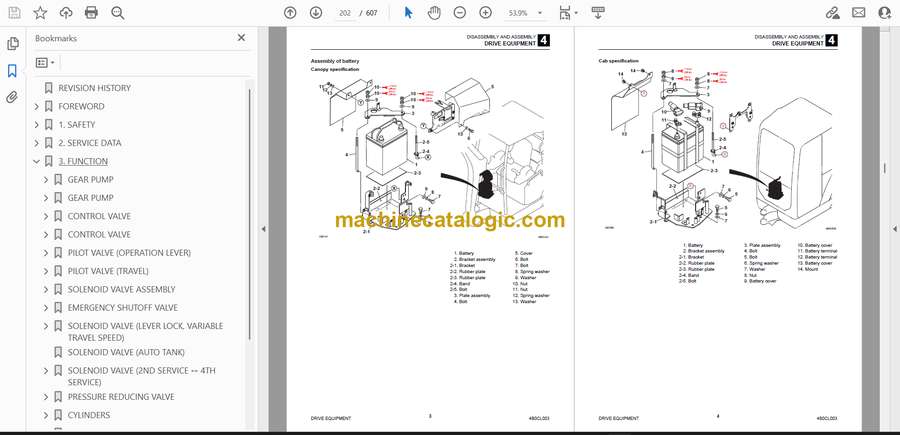
- Assembly of battery
- Canopy specification
- Cab specification
- Disassembly and assembly
- Removal and installation of the inverter
- Removal and installation of the on-board charger
- Removal and installation of the battery
- TRAVEL EQUIPMENT
- Construction diagram
- Assembly of track roller
- Assembly of shoe slide
- Assembly of front idler
- Assembly of travel motor
- Assembly of lower frame
- Disassembly and assembly
- Removal of the rubber crawler
- Installation of the rubber crawler
- Removal and installation of the shoe slide
- Removal of the track roller
- Installation of the track roller
- Removal and installation of the front idler assembly
- Removal and installation of the travel motor
- SLEW EQUIPMENT
- Construction diagram
- Assembly of slew motor
- Assembly of slew bearing
- Assembly of swivel joint
- Disassembly and assembly
- Removal and installation of the slew motor
- Removal and installation of the slew bearing
- Removal and installation of the swivel joint
- UPPER FRAME
- Construction diagram
- Assembly of main unit
- Assembly of grease piping
- Assembly of cover
- Canopy specification
- Cab specification
- Assembly of canopy mounting
- Assembly of cab mounting
- Assembly of floor
- Canopy specification
- Cab specification
- Floor frame assembly
- Canopy specification
- Cab specification
- Assembly of operator seat
- Disassembly and assembly
- Removal and installation of the main unit assembly
- Removal and installation of the battery cover assembly
- Removal and installation of the side cover assembly
- Removal and installation of the canopy assembly
- Removal and installation of the cab assembly
- Removal of the glass
- Installation of the glass
- CONTROL EQUIPMENT
- Construction diagram
- Assembly of control lever
- Assembly of blade control lever
- Assembly of pilot piping
- Assembly of right control box
- Canopy specification
- Cab specification
- Assembly of left control box
- Canopy specification
- Cab specification
- Disassembly and assembly
- Calibration of the boom swing operation pedal and blade control lever
- WORK EQUIPMENT
- Construction diagram
- Assembly of bucket
- Assembly of arm
- Assembly of boom
- Boom cylinder assembly
- Arm cylinder assembly
- Assembly of boom swing
- Assembly of blade
- Disassembly and assembly
- Removal and installation of the bucket
- Release of residual pressure
- Removal and installation of the arm assembly
- Removal and installation of the boom assembly
- Removal and installation of the boom bracket
- Removal and installation of the blade
- Removal and installation of only each cylinder
- Removal and installation of the bucket cylinder
- Removal and installation of the arm cylinder
- Removal and installation of the boom cylinder
- Removal and installation of the swing cylinder
- HYDRAULIC OIL TANK
- Construction diagram
- Assembly of hydraulic oil tank
- Oil cooler assembly
- Canopy specification
- Cab specification
- Hydraulic oil tank assembly
- Disassembly and assembly
- Removal and installation of the hydraulic oil tank
- Oil level inspection and replenishment of the hydraulic oil tank
- Method for bleeding air
- GEAR PUMP (SUB PUMP)
- Construction diagram
- Disassembly and assembly
- CONTROL VALVE
- Construction diagram
- Control valve
- Block assembly (inlet)
- Block assembly (bucket)
- Block assembly (boom)
- Block assembly (travel (right))
- Block assembly (travel (left))
- Block assembly (arm)
- Block assembly (1st service)
- Block assembly (2nd service)
- Block assembly (swing)
- Block assembly (blade)
- Block assembly (outlet)
- Main relief valve
- Overload relief valve
- Anti-cavitation valve
- Disassembly and assembly
- Precautions for disassembly
- Precautions for assembly
- Removal and installation of each valve
- Removal and installation of each block assembly
- Disassembly and assembly of the block assembly (inlet)
- Disassembly and assembly of the block assembly (boom)
- Disassembly and assembly of the anti-drift valve assembly
- Disassembly and assembly of the block assembly (outlet)
- Disassembly and assembly of other block assemblies
- Disassembly of each valve
- Cleaning of each part
- Inspection of each part
- Operation
- CONTROL VALVE
- Construction diagram
- Control valve
- Block assembly (inlet)
- Block assembly (3rd service)
- Block assembly (slew)
- Main relief valve
- Overload relief valve
- Disassembly and assembly
- Precautions for disassembly
- Precautions for assembly
- Removal and installation of the relief valve
- Removal and installation of each block assembly
- Disassembly and assembly of the block assembly (inlet)
- Disassembly and assembly of the block assembly (3rd service)
- Disassembly and assembly of the block assembly (slew)
- Disassembly of the main relief valve and overload relief valve
- Cleaning of each part
- Inspection of each part
- Operation
- SOLENOID VALVE ASSEMBLY
- Construction
- Disassembly and assembly
- Proportional solenoid valve (2)
- Solenoid valve (3): 3rd service release pressure and slew parking brake release pressure
- Inspection and adjustment
- EMERGENCY SHUTOFF VALVE
- SOLENOID VALVE (DUAL-SECTION)
- Construction
- Disassembly and assembly
- Inspection and adjustments
- SOLENOID VALVE (AUTO TANK)
- Construction
- Disassembly and Assembly
- Inspection and adjustments
- SOLENOID VALVE
- Construction diagram
- Disassembly and assembly
- Inspection and adjustment
- PRESSURE REDUCING VALVE
- Construction diagram
- Disassembly and assembly
- CYLINDER
- Construction diagram
- Boom cylinder
- Bucket cylinder
- Blade cylinder
- Swing cylinder
- Disassembly and assembly
- Preparation
- Service standard
- Inspection after assembly
- Special tools
- Disassembly
- Assembly
- TRAVEL MOTOR
- Construction
- Hydraulic motor
- Reduction gears
- Valves
- Assembly
- Counter balance valve and hydraulic motor
- Reduction gears
- Inspection and adjustments
- SLEW MOTOR
- Reduction gear
- Hydraulic motor
- Relief valve
- Disassembly and assembly
- Tools required for disassembly and assembly
- Disassembly
- Assembly
- SWIVEL JOINT
- Construction
- Disassembly and Assembly
- Inspection and adjustment
- Inspection procedures and remedial actions
- Use limit for parts
- Inspection after assembly
- WIRE HARNESS
- MAIN UNIT HYDRAULIC PIPING & LOWER HYDRAULIC PIPING
- Main unit hydraulic piping assembly
- Construction diagram
- Table of connections
- Lower hydraulic piping assembly
- Construction diagram
- Table of connections
- 5. TROUBLESHOOTING
- TROUBLESHOOTING
- Notes on the malfunction diagnosis and repair
- GENERAL
- The motor rotation speed cannot be increased.
- 1. Did an error code occur?
- 2. Is the decelerator lamp lit?
- 3. Is the speed controller set to “Low”?
- All the attachments and travel motors are inoperable.
- 1. Did an error code occur?
- 2. Is the specified amount of hydraulic oil available?
- 3. Does the motor rotate when the lever lock is lowered?
- 4. Is the pilot pressure within the standard value range?
- 5. Is the main pressure within the standard value range?
- All the attachments and travel motors operate but are slow.
- 1. Does the motor rotation speed reach the maximum?
- 2. Is the specified amount of hydraulic oil available?
- 3. Is the pump making an abnormal noise?
- 4. Is the pilot pressure within the standard value range?
- 5. Is the main pressure within the standard value range?
- TRAVEL
- The travel motors are inoperable (both left and right or one of them).
- 1. Did an error code occur?
- 2. Do hydraulic devices other than travel motors operate?
- 3. Do travel inputs and outputs occur with the main controller?
- 4. Is the discharge pressure from the proportional solenoid valve (travel) normal?
- 5. Is the discharge pressure from the control valve (travel section) normal?
- 6. Is the discharge pressure from the swivel joint normal?
- The vehicle veers to one side with the left or right travel speed slowing down when it travels forward or backward.
- 1. Is the crawler tension normal?
- 2. Is any foreign matter trapped in the crawler?
- 3. Do travel inputs and outputs occur for both left and right travel with the main controller?
- 4. Is the discharge pressure from the proportional solenoid valve (travel) normal?
- 5. Is the discharge pressure from the control valve (travel section) normal?
- 6. Is the discharge pressure from the swivel joint normal?
- The variable travel speed cannot be changed.
- 1. Do variable travel speed inputs and outputs occur with the main controller?
- 2. Is the variable travel speed pressure from the solenoid valve (variable travel speed) normal?
- 3. Is the variable travel speed pressure from the swivel joint normal?
- SLEW
- The vehicle cannot slew.
- 1. Did an error code occur?
- 2. Do hydraulic devices other than slew operate normally?
- 3. Is the slew pressure within the standard value range?
- 4. Is the hydraulic piping that supplies the slew brake release pressure abnormal?
- 5. Does the slew bearing rotate?
- 6. Do slew inputs and outputs occur with the main controller?
- 7. Is the discharge pressure from the proportional solenoid valve (slew) normal?
- 8. Is the discharge pressure from the control valve (slew section) normal?
- The vehicle cannot slew to the left or right.
- 1. Is the slew pressure within the standard value range?
- 2. Is the hydraulic piping that supplies the slew brake release pressure abnormal?
- 3. Do slew inputs and outputs occur for both left and right slew with the main controller?
- 4. Is the discharge pressure from the proportional solenoid valve (slew) normal?
- 5. Is the discharge pressure from the control valve (slew section) normal?
- 6. Is the slew relief valve normal?
- The vehicle can slew but is slow and lacks power.
- 1. Do hydraulic devices other than slew operate normally?
- 2. Is the slew pressure below the standard value range?
- 3. Is the slew relief valve or relief valve seat abnormal?
- 4. Does the main controller slew input (operation distance) reach 100%?
- 5. Is the discharge pressure from the proportional solenoid valve (slew) normal?
- 6. Is the discharge pressure from the control valve (slew section) normal?
- The slewing stop flow rate is large or the vehicle cannot stop.
- 1. Is the slew pressure below the standard value range?
- 2. When the pilot valve (slew) is set to the neutral position, does the main controller slew input (operation distance) reach 0%?
- 3. Can the control valve (slew section) be set to the neutral position?
- BOOM
- The boom cannot be raised or lowered.
- 1. Did an error code occur?
- 2. Do hydraulic devices other than the boom operate?
- 3. Do boom inputs and outputs occur with the main controller?
- 4. Is the discharge pressure from the proportional solenoid valve (boom) normal?
- 5. Is the discharge pressure from the control valve (boom section) normal?
- The boom can be raised or lowered but is slow and lacks power.
- 1. Do hydraulic devices other than the boom operate normally?
- 2. Does the main controller boom input (operation distance) reach 100%?
- 3. Is the discharge pressure from the proportional solenoid valve (boom) normal?
- 4. Is the discharge pressure from the control valve (boom section) normal?
- 5. Is the boom cylinder leaking internally?
- The boom is temporarily lowered when the boom control lever is slowly pulled.
- 1. Is the boom cylinder leaking internally?
- The amount of boom natural drop is large.
- 1. Is the boom cylinder leaking internally?
- 2. Is the boom emergency shutoff valve leaking internally?
- ARM
- The arm cannot be pushed or pulled.
- 1. Did an error code occur?
- 2. Do hydraulic devices other than the arm operate?
- 3. Do arm inputs and outputs occur with the main controller?
- 4. Is the discharge pressure from the proportional solenoid valve (arm) normal?
- 5. Is the discharge pressure from the control valve (arm section) normal?
- The arm can be pushed and pulled but is slow and lacks power.
- 1. Do hydraulic devices other than the arm operate normally?
- 2. Does the main controller arm input (operation distance) reach 100%?
- 3. Is the discharge pressure from the proportional solenoid valve (arm) normal?
- 4. Is the discharge pressure from the control valve (arm section) normal?
- The amount of arm natural drop is large.
- 1. Is the arm emergency shutoff valve leaking internally?
- BUCKET
- The bucket cannot dig or remove soil.
- 1. Did an error code occur?
- 2. Do hydraulic devices other than the bucket operate?
- 3. Do bucket inputs and outputs occur with the main controller?
- 4. Is the discharge pressure from the proportional solenoid valve (bucket) normal?
- 5. Is the discharge pressure from the control valve (bucket section) normal?
- The bucket can dig and remove soil but is slow and lacks power.
- 1. Do hydraulic devices other than the bucket operate normally?
- 2. Does the main controller bucket input (operation distance) reach 100%?
- 3. Is the discharge pressure from the proportional solenoid valve (bucket) normal?
- 4. Is the discharge pressure from the control valve (bucket section) normal?
- The amount of bucket natural drop is large.
- 1. Is there an abnormality, such as leaking, in the hydraulic piping connected to the bucket cylinder?
- SWING
- Swing operation cannot be performed.
- 1. Did an error code occur?
- 2. Do hydraulic devices other than swing operate?
- 3. Do swing inputs and outputs occur with the main controller?
- 4. Is the discharge pressure from the proportional solenoid valve (swing) normal?
- 5. Is the discharge pressure from the control valve (swing section) normal?
- Swing operation can be performed but is slow and lacks power.
- 1. Do hydraulic devices other than swing operate normally?
- 2. Does the main controller swing input (operation distance) reach 100%?
- 3. Is the discharge pressure from the proportional solenoid valve (swing) normal?
- 4. Is the discharge pressure from the control valve (swing section) normal?
- The amount of swing natural drop is large.
- 1. Is there an abnormality, such as leaking, in the hydraulic piping connected to the swing cylinder?
- BLADE
- The blade cannot be raised or lowered.
- 1. Did an error code occur?
- 2. Do hydraulic devices other than the blade operate?
- 3. Do blade inputs and outputs occur with the main controller?
- 4. Is the discharge pressure from the proportional solenoid valve (blade) normal?
- 5. Is the discharge pressure from the control valve (blade section) normal?
- 6. Is the discharge pressure from the swivel joint normal?
- The blade can be raised or lowered but is slow and lacks power.
- 1. Do hydraulic devices other than the blade operate normally?
- 2. Does the main controller blade input (operation distance) reach 100%?
- 3. Is the discharge pressure from the proportional solenoid valve (blade) normal?
- 4. Is the discharge pressure from the control valve (blade section) normal?
- 5. Is the discharge pressure from the swivel joint normal?
- The amount of blade natural drop is large.
- 1. Is there an abnormality, such as leaking, in the hydraulic piping connected to the blade cylinder?
- SERVICE
- The attachment connected to the 1st service is inoperable.
- 1. Did an error code occur?
- 2. Do hydraulic devices other than the 1st service operate?
- 3. Do 1st service inputs and outputs occur with the main controller and sub-controller?
- 4. Is the pressure on the 1st service A and B within the standard value range?
- 5. Is the discharge pressure from the proportional solenoid valve (1st service) normal?
- The attachment connected to the 2nd service is inoperable.
- 1. Did an error code occur?
- 2. Do hydraulic devices other than the 2nd service operate?
- 3. Do 4th service switching button inputs and outputs occur with the main controller?
- 4. Do 2nd service inputs and outputs occur with the main controller and sub-controller?
- 5. Is the pressure on the 2nd service A and B within the standard value range?
- 6. Is the discharge pressure from the proportional solenoid valve (2nd service) normal?
- 7. Is the discharge pressure from the control valve (2nd service section) normal?
- The quick-hitch cannot be locked (3rd service).
- 1. Did an error code occur?
- 2. Do hydraulic devices other than the quick-hitch operate normally?
- 3. Is the pressure on the 3rd service A within the standard value range?
- 4. Is there an abnormality in the hydraulic piping connected to the 3rd service A?
- The quick-hitch cannot be unlocked (3rd service).
- 1. Did an error code occur?
- 2. Do hydraulic devices other than the quick-hitch operate normally?
- 3. Is the pressure on the 3rd service B within the standard value range?
- 4. Do 3rd service inputs and outputs occur with the main controller?
- 5. Is the discharge pressure from the solenoid valve (3rd service) normal?
- SPAN
- Span operation (extension and retraction) cannot be performed.
- 1. Did an error code occur?
- 2. Do hydraulic devices other than span operate?
- 3. Is the linkage normal?
- 4. Do blade inputs and outputs occur with the main controller?
- 5. Is the discharge pressure from the proportional solenoid valve (blade) normal?
- 6. Is the discharge pressure from the control valve (blade section) normal?
- 7. Is the discharge pressure from the swivel joint normal?
- GEAR PUMP
- GEAR PUMP
- CONTROL VALVE
- 1. Control valve in general
- 2. Relief valve
- 3. Hydraulic control in general
- SOLENOID VALVE
- CYLINDER
- SLEW MOTOR
- BATTERY PACK
- 6. OTHER
- MAINTENANCE SOFTWARE MANUAL
- CONTENTS
- 1. OVERVIEW
- 2. CONNECTION METHOD
- 2-1. Parts needed
- 2-2. Installation method
- 2-3. Connection to work machine and startup of maintenance software
- LEVER SWITCH PATTERN SWITCHING METHOD
- Included parts
- Pattern switching method
- Standard lever switch pattern
- Case 1: When switching the 1st service and the 2nd service
- Case 2: When switching A and B or switching C and D
- Case 3: When switching the 1st service and the 2nd service and also switching A and B or switching C and D
- AUX1 Detent mode: When assigning the detent function to the button B
- VEHICLE ERROR CODES
- Diagnostics procedures for malfunctions and failure
- Repair procedures
- How to check the detection ports
- TABLE OF VEHICLE ERROR CODES
- TABLE OF BATTERY PACK ERROR CODES
- TABLE OF MOTOR ERROR CODES
- TABLE OF CHARGER ERROR CODES
- Table of error codes
- Details of error codes
- A01: LOGIC FAILURE #1
- A02: BMS OFFLINE
- A03: WATCHDOG
- A06: MISSING PHASE
- A07: OVERCURRENT
- A08: HIGH TEMPERATURE
- A09: MISMATCH VOLTAGE
- A16: LOGIC FAILURE #2
- A17: FLASH CHECKSUM
- A18: EEPROM KO
- A21: LOGIC FAILURE #3
- A23: POWER FAILURE #1 (on-board charger only)
- A24: WRONG INPUT VOLTAGE (on-board charger only)
- A25: SHORTED OUTPUT (on-board charger only)
- A26: WRONG MARKER EEP (on-board charger only)
- A27: NO MAINS (on-board charger only)
- A28: LOW TEMPERATURE (on-board charger only)
- A29: CLOCK BATTERY OFF
- A31: NODES MISMATCH
- A33: MASTER NOT FOUND
- A37: FIRMWARE MISMATCH
- A40: BMS OVERVOLTAGE
- A41: CLEAR EEPROM REQUEST
- A60: WRONG PROTOCOL
- SOH UPDATE PROCEDURE
Takeuchi


