Takeuchi TB230 Mini Excavator Workshop Manual (CE8E918) (SN 130000003-)
On a TB230 that spends its days trenching, grading around buildings, or working in tight utility easements, this workshop manual is what I’d pull out when the job goes beyond simple checks. It walks you through how to strip, repair, and correctly put major components back together so the machine tracks straight, digs clean, and doesn’t come back with the same fault. For example, if you’ve got a boom drift or weak travel on one side, this is the document I’d use to trace the issue, test components in order, and verify everything is reinstalled safely.
Applications & Use Cases
- Planning a repair sequence before tearing into the boom, arm, or undercarriage so you don’t miss hidden fasteners or adjustment points.
- Tracing hydraulic faults and isolating whether the problem is in a cylinder, valve, or pump before ordering parts.
- Inspecting wear items—pins, bushings, seals—and confirming what must be renewed during a rebuild.
- Verifying reassembly of swing, travel, and attachment systems so hoses are routed correctly and components are aligned.
- Performing post-repair tests to confirm pressures, movements, and safety functions are back within normal behavior.
FAQ
Q: Can I use this manual on a tablet in the field?
A: Yes, it’s practical on a tablet; you can zoom diagrams and keep it open next to the machine while you work.
Q: Is it worth printing sections of this manual?
A: Printing the procedures you use most often is handy, so you can mark torque steps, test points, and inspection notes without worrying about dirt or damage.
Safety Note
Always follow the manual’s support, lockout, and pressure-release steps before loosening any component on the TB230.
Takeuchi TB230 Mini Excavator Index:
- REVISION HISTORY
- FOREWORD
- Directional terms: front, rear, left, right
- Machine serial number
- Symbols used in this manual
- Manual structure
- 1. SAFETY
- SAFETY ALERT SYMBOL
- SAFETY PRECAUTIONS
- Observe all safety rules
- Wear safe clothing and protective gear
- Install an extinguisher and a first aid kit
- Lockout/Tagout (LOTO)
- Use the correct tools
- Regularly replace the safety-critical parts
- Explosionproof lighting
- Prohibit access by unauthorized persons
- Prepare the work area
- When the canopy is tilted up
- Keep the machine clean
- Stop the engine before performing maintenance
- Keep clear of the moving fan and belt
- When working under the machine
- When working on the machine
- Securing the working equipment
- Secure the engine hood and guard when they are open
- Place heavy components in a stable position
- Caution when filling with fuel or oil
- Preventing Fire and Explosion
- Be careful with hot and pressurized components
- Handling of radiator
- Be careful with oils under pressure
- Release the residual pressure from the hydraulic system before performing maintenance
- Be careful with grease under pressure
- Handling of the accumulator
- Disconnect the battery
- Use caution when handling batteries
- Have a service agent repair welding cracks or other damage
- Checks after maintenance
- Disposing of wastes
- Always maintain 3 points of contact when getting on and off the machine.
- Cautions when starting the engine
- Do not allow anyone other than the operator on the machine.
- If the cab or canopy is damaged
- Beware of fragments when working with a hammer
- Precautions when performing maintenance on the air conditioner
- CAUTIONS WHEN WORKING
- Before starting work
- When disassembling or assembling
- When removing/installing the hydraulic unit
- When connecting/disconnecting the hoses or pipes
- Handling of seals
- Pressure adjustment for hydraulic devices
- 2. SERVICE DATA
- DIMENSIONAL DRAWING
- Machine dimensions
- Operating range
- SPECIFICATION TABLES
- Performance
- Dimensions of complete machine
- Dimensions of base machine
- Engine
- Hydraulic system
- Operating device
- Slew equipment
- Lower machinery
- Working equipment
- Working dimensions
- Main structure
- Digging force
- Dozer blade
- TABLE OF MASSES
- Upper structure
- Lower structure
- Hoe attachments
- LUBRICANT AND FUEL CHART
- PERFORMANCE CRITERIA
- Standard values table
- Hydraulic pump assignment table
- Pump P1
- Pump P2
- Pump P3
- Pump P4
- Methods for inspecting performance
- Hydraulic oil pressure (Main relief valve set pressure)
- Travel speed (5 revolutions)
- Travel speed (10 m)
- Straight-ahead traveling
- Natural travel drop
- Slew time
- Overrun when slewing stops
- Natural slew drop
- Boom cylinder speed
- Arm cylinder speed
- Bucket cylinder speed
- Dozer blade cylinder speed
- Swing cylinder speed
- Natural cylinder drop
- Swing cylinder
- Lever play
- Backlash
- Slew bearing play
- Crawler tension
- TIGHTENING TORQUE
- Hydraulic hose
- Bite-type pipe fitting for steel pipe
- Joint for piping
- Joint for piping (O-ring seal type)
- Bolts and nuts (JIS strength category 10.9)
- HYDRAULIC CIRCUIT DIAGRAM
- ELECTRICAL CIRCUIT DIAGRAM
- Symbols in electrical circuit diagram
- Wire color symbols
- Wire color table
- Wire types
- Schematic diagram
- Canopy
- Serial No.: 130000003 to 130000350
- Serial No.: 130000351 to 130002923
- Serial No.: 130002924 to 130004270
- Serial No.: 130004271 to 130005587
- Serial No.: 130005588 to 130006592
- Serial No.: 130006593 to 130007213
- Serial No.: 130007214 to 130007478
- Serial No.: 130007479 to 130007921
- Serial No.: 130007922 or later
- Cab
- Serial No.: 130000003 to 130000350
- Serial No.: 130000351 to 130002272
- Serial No.: 130002273 to 130002923
- Serial No.: 130002924 to 130004270
- Serial No.: 130004271 to 130005587
- Serial No.: 130005588 to 130006592
- Serial No.: 130006593 to 130007213
- Serial No.: 130007214 to 130007478
- Serial No.: 130007479 to 130007921
- Serial No.: 130007922 to 130011923
- Serial No.: 130011924 or later
- 3. FUNCTION
- HYDRAULIC PUMP (PISTON)
- Discharge volume control mechanism
- GEAR PUMP
- CONTROL VALVE
- Overview
- Standard specification
- Angle blade specification
- 2nd service/3rd service/angle blade specification
- Operation
- Bucket
- Boom
- P1 travel
- P1 and P2 inlets
- P2 travel
- Arm
- Swing
- 1st service
- Slew
- Blade
- 2nd service
- Angle blade
- Communication valve
- Main relief valve
- Overload relief valve
- Anti-cavitation valve
- PILOT VALVE (CONTROL LEVER)
- PILOT VALVE (SWING)
- PILOT VALVE (BLADE)
- PILOT VALVE (TRAVEL)
- PROPORTIONAL SOLENOID VALVE (POWER CONTROL)
- EMERGENCY SHUT-OFF VALVE
- Neutral (Positions maintained)
- Boom cylinder raising and arm cylinder dumping operations
- Boom cylinder lowering and arm cylinder excavator operations
- Relief valve operation (When an abnormal high pressure is produced in the cylinder)
- SOLENOID VALVE (AUTO TANK)
- SOLENOID VALVE (3RD AUXILIARY LINE PIPING)
- SOLENOID VALVE
- SOLENOID VALVE (LEVER LOCK, SPEED SHIFT TRAVEL)
- Solenoid switching/relief function
- When not energized
- When energized
- Check function
- SELECTOR VALVE
- CYLINDERS
- TRAVEL MOTOR
- Hydraulic motor
- Counter balance valve
- 2-speed mechanism
- 2nd speed control valve
- Swash plate
- Automatic 2-speed switching system
- Parking brake
- Reduction gears
- SLEW MOTOR
- Hydraulic motor
- Relief valve
- The 1st stage
- The 2nd stage
- Make-up valve
- Anti-rebound valve
- When the brake is actuated
- When the Motor Rebounds
- Parking brake
- Timer valve
- Reduction gears
- SWIVEL JOINT
- 4. DISASSEMBLY AND ASSEMBLY
- SERVICE STANDARDS
- Carrier roller
- Track roller
- Sprocket
- Idler
- Clearance for pin and bushing
- Replacing the pin and bushing
- DRIVE SYSTEM
- Engine
- Removing the engine
- Installing the engine
- Hydraulic pump
- Removing the hydraulic pump
- Installing the hydraulic pump
- Fuel tank
- With fuel filler pump
- Removing the fuel tank
- Installing the fuel tank
- Fuel filler pump
- Serial No.: 130000003-130000332
- Serial No.: 130000333-
- Battery
- Removing the battery
- Installing the battery
- TRAVEL SYSTEM
- Removing the crawler
- Installing the crawler
- Removing the steel crawler
- Installing the steel crawler
- Removing the carrier roller
- Installing the carrier roller
- Removing the track roller
- Installing the track roller
- Removing the idler and track adjuster
- Installing the idler and track adjuster
- Removing the travel motor
- Installing the travel motor
- SLEW EQUIPMENT
- Slew motor
- Removing the slew motor
- Installing the slew motor
- Slew bearing
- Removing the slew bearing
- Installing the slew bearing
- Swivel joint
- Removing the swivel joint
- Installing the swivel joint
- UPPER FRAME
- Upper frame
- Removing the upper frame
- Installing the upper frame
- Covers
- Removing the covers
- Attaching the covers
- Cab
- Removing the cab assembly
- Installing the cab assembly
- Canopy
- Removing the canopy assembly
- Installing the canopy assembly
- Floor frames
- Cab specification
- Canopy specification
- Removing the glass window panes
- Installing glass window panes
- CONTROL DEVICE
- Construction diagram
- Control levers
- Blade lever
- Blade lever (Float)
- Valve bracket (Left)
- Serial No.: 130000003 to 130000236
- Serial No.: 130000237 or later
- Valve bracket (Right)
- Serial No.: 130000003 to 130000236
- Serial No.: 130000237 or later
- Control box L
- Control box R
- Hydraulic pilot unit
- Type A (ISO) ↔ Type G (JCB)
- Table of connections
- Type A (ISO)
- Table of connections
- Disassembly and assembly
- Removal and installation of the accumulator
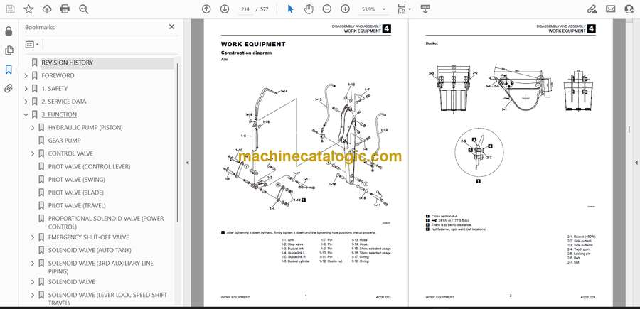
- WORK EQUIPMENT
- Construction diagram
- Arm
- Bucket
- Boom
- Boom bracket
- Blade
- Disassembly and assembly
- Removal and installation of the bucket
- Removal and installation of the link
- Release of residual pressure
- Removal and installation of the arm
- Removal and installation of the boom
- Removal and installation of the boom bracket
- Removal and installation of the blade
- HYDRAULIC TANK
- Removing the hydraulic tank
- Installing the hydraulic tank
- HYDRAULIC PUMP
- Construction
- Disassembly and assembly
- Inspection and adjustments
- CONTROL VALVE
- Construction
- Standard specifications
- Equipped with angle blade
- With third auxiliary line piping and angle blade included
- Bucket section
- Boom section
- Right travel section
- Left travel section
- Arm section
- Swing section
- 1st auxiliary line piping
- Slew section
- Blade section
- 2nd auxiliary line piping section
- Angle blade section
- Coupling valve section
- Inlet housing
- Main relief valve
- Port relief valve
- Anti-cavitation valve
- Disassembly and Assembly
- General precautions
- Disassembly
- Inspection and adjustment
- PILOT VALVE
- Construction
- Special tools
- Installation jig A
- Installation jig B
- Disassembly and Assembly
- Inspection and adjustment
- PILOT VALVE (SWING, BLADE)
- Construction
- Special Jigs
- Disassembly and Assembly
- Inspection and adjustment
- PILOT VALVE (TRAVEL)
- Construction
- Disassembly and Assembly
- Special Jigs
- Disassembly
- Assembly
- Inspection and adjustment
- PROPORTIONAL SOLENOID VALVE (POWER CONTROL)
- Construction
- Disassembly and Assembly
- Inspection and adjustments
- PROPORTIONAL SOLENOID VALVE (1ST/2ND SERVICE)
- Construction
- Disassembly and Assembly
- Inspection and adjustment
- EMERGENCY SHUTOFF VALVE
- SOLENOID VALVE (AUTO TANK)
- Construction
- Disassembly and Assembly
- Inspection and adjustments
- SOLENOID VALVE (1ST/2ND AUX)
- Construction
- Disassembly and Assembly
- Inspection and adjustment
- SOLENOID VALVE (ANGLE BLADE)
- Construction
- Disassembly and Assembly
- Inspection and adjustment
- SOLENOID VALVE (BLADE FLOAT)
- Construction
- Disassembly and Assembly
- Inspection and adjustment
- SOLENOID VALVE (3RD AUXILIARY LINE PIPING)
- Construction
- Disassembly and Assembly
- Inspection and adjustment
- SOLENOID VALVE (LEVER LOCK)
- Construction
- Disassembly
- Solenoid valve
- Relief valve
- Check valve
- Assembly
- Inspection and adjustment
- SOLENOID VALVE (4TH AUX)
- Construction
- Disassembly and Assembly
- Inspection and adjustment
- SELECTOR VALVE
- Construction
- Disassembly and Assembly
- Inspection and adjustment
- REDUCING VALVE
- Construction
- Disassembly and Assembly
- Inspection and adjustment
- ANGLE CYLINDER
- Construction
- Disassembly and Assembly
- Special tools
- Disassembly
- Assembly
- Inspection and adjustment
- Inspection after disassembly
- Inspection after assembly
- CYLINDERS (BOOM, ARM, DOZER BLADE)
- Construction
- Boom cylinder
- Boom cylinder (With emergency shut-off valve attached)
- Arm cylinder
- Arm cylinder (With emergency shut-off valve attached)
- Dozer blade cylinder
- Disassembly and assembly
- Special tools
- Disassembly
- Assembly
- Inspection and adjustment
- Inspection after disassembly
- Inspection after assembly
- CYLINDERS (BUCKET, SWING)
- Construction
- Bucket cylinder
- Swing cylinder
- Disassembly and Assembly
- Special tools
- Disassembly
- Assembly
- Inspection and adjustment
- Inspection after disassembly
- Inspection after assembly
- TRAVEL MOTOR
- Construction
- Reduction gears
- Hydraulic motor
- Valve assembly
- Special tools
- Disassembly and assembly
- Assembly
- Inspection and adjustment
- SLEW MOTOR
- Construction
- Hydraulic motor
- Reduction gears
- Brake valve
- Special tools
- Disassembly and Assembly
- Disassembly
- Slew motor
- Brake valve and hydraulic motor
- Reduction gears
- Assembly
- Brake valve and hydraulic motor
- Reduction gears
- Slew motor
- Inspection and adjustment
- SWIVEL JOINT
- Construction
- Disassembly and Assembly
- Inspection and adjustment
- Inspection procedures and remedial actions
- Use limit for parts
- Inspection after assembly
- WIRE HARNESS
- Electrical wiring assembly (canopy specification), Serial No.: 130000003-130000604 (for EU) / Serial No.: 130000003- (not for EU)
- Wire harness assembler: 03542-00025-02
- Harness: 03742-00043-03 (Serial No.: 130000003-130000922)
- Harness: 03742-00065-00 (Serial No.: 130000923-)
- Wire harness: 03742-00006-00
- Wire harness: 03542-00007-02
- Electrical wiring assembly (cab specification), Serial No.: 130000003-130000604 (for EU) 130000003- (not for EU)
- Wire harness: 03542-00025-02
- Harness: 03742-00037-05
- Harness: 03742-00034-00
- Wire harness: 05542-00057-01
- Wire harness assembly: 03542-00007-02
- Electrical wiring assembly (canopy specification), Serial No.: 130000605- (for EU)
- Wire harness assembly: 03542-00025-02
- Harness: 03742-00043-03
- Wire harness: 03742-00006-00
- Wire harness: 03542-00007-02
- Electrical wiring assembly (cab specification), Serial No.: 130000605- (for EU)
- Wire harness assembly: 03542-00025-02
- Wire harness assembly: 03742-00037-05
- Wire harness assembly: 05542-00057-01
- Wire harness assembly: 03542-00034-00
- Wire harness: 03542-00007-02
- GPS unit assembly
- Cab harness
- Wire harness: 03586-00082-01
- Wire harness: 05686-60590-00
- 5. TROUBLESHOOTING
- ABOUT THE TROUBLESHOOTING SECTION
- Notes on troubleshooting and servicing
- OVERALL MACHINE
- No operation is possible.
- All systems working, but insufficient power.
- Boom, bucket, slew and arm fail to move or are too slow.
- TRAVELING
- No right or left travel.
- Right or left travel speed decelerates and the machine veers to one side.
- 2nd-speed travel is not possible.
- SLEWING
- No slew movement.
- No right or left slew movement.
- Slewing is slow or lacks force.
- Slewing occurs but overrun is large when slewing stops or slewing does not stop.
- When stopped on a slope, the upper-structure cannot maintain its posture.
- BOOM
- Boom cylinder does not move.
- Boom cylinder is slow or lacks force.
- When the control lever is pulled slowly, the boom drops temporarily.
- Spontaneous drop of the boom cylinder is too large.
- ARM
- Arm cylinder does not move.
- Arm cylinder is slow or lacks force.
- Spontaneous drop of the arm is too large.
- BUCKET
- Bucket cylinder does not move or lacks force.
- Spontaneous drop of the bucket is too large.
- BOOM SWING
- Swing cylinder does not move.
- AUXILIARY HYDRAULICS
- Prescribed pressure not supplied to the 1st and 2nd auxiliary lines.
- ANGLE BLADE
- Angle cylinder does not move.
- Angle cylinder lacks force.
- HYDRAULIC PUMP
- GEAR PUMP
- CONTROL VALVE
- PILOT VALVE
- SOLENOID VALVE
- CYLINDERS
- TRAVEL MOTOR
- Hydraulic motor
- 2nd-speed control
- Parking brake
- SLEW MOTOR
- Hydraulic motor, brake valve
- Parking brake
- 6. OTHER
- MAINTENANCE SOFTWARE MANUAL
- CONTENTS
- 1. OUTLINE
- 2. CONNECTION METHODS
- 2-1. Items needed
- 2-2. Installation method
- 2-2-1. Installation of the PLUS+1 Service Tool
- 2-2-2. Installation of the maintenance tool driver
- 2-3. Connection to the machine and startup of the maintenance software
- 3. DESCRIPTION OF FUNCTIONS
- 3-1. Home (Main screen)
- 3-2. Maintenance menu
- 3-2-1. Monitor
- 3-2-2. Inputs
- 3-2-3. Outputs
- 3-2-4. Feedback
- 3-2-5. Error Code
- 3-3. Setting menu
- 3-3-1. Vehicle Status
- 3-3-2. Engine
- 3-3-3. AUX1
- 3-3-4. AUX2/4
- 3-3-5. Misc
- 3-3-6. Liftalarm
- 3-3-7. Immobillzer
- 3-3-8. Pattern change
- 3-3-9. Option
- 3-3-10. Hourmeter
- 3-3-11. Auto engine stop
- HOW TO ENABLE THE AUX4 FUNCTION
- VEHICLE ERROR CODES
Takeuchi


