Takeuchi TB235-2 Mini Excavator Workshop Manual (CE9E018) (SN 123600005-)
On a TB235-2 that spends its life trenching, loading spoil, and working around utilities, this workshop manual is what I’d keep open on the bench when the machine comes in for real repairs, not just greasing. It walks you through how to strip, inspect, and correctly reinstall the major components so they go back together tight and safe. For example, if the boom starts drifting down or the swing feels loose, this is the guide I’d use to trace the fault, pull the right parts, and verify everything is set up properly when it goes back on the job.
Applications & Use Cases
- Planning a repair sequence before tearing down the boom, arm, or travel system so you don’t miss hidden fasteners or seals.
- Tracing hydraulic issues and isolating whether the problem is in a cylinder, valve, or piping before ordering parts.
- Inspecting wear points on pins, bushings, and slew components with clear criteria for when to replace.
- Reassembling and aligning components so hoses are routed cleanly and nothing binds or rubs once the machine is back in service.
- Performing post-repair checks to test functions, bleed air, and verify the excavator is safe to return to the site.
FAQ
Q: Can I use this manual on a tablet in the field?
A: Yes, it’s practical to keep it on a tablet or laptop so you can zoom diagrams and search terms while standing next to the machine.
Q: Is it worth printing parts of this manual?
A: Many techs print the procedures they’re doing that day, mark them up with notes, and keep the clean copy saved digitally.
Safety Note
Always follow the lockout, support, and pressure-release steps in the manual before loosening any component on the machine.
Takeuchi TB235-2 Mini Excavator Index:
- REVISION HISTORY
- FOREWORD
- Directional terms: front, rear, left, right
- Machine serial number
- Symbols used in this manual
- Manual structure
- 1. SAFETY
- SAFETY ALERT SYMBOL
- SAFETY PRECAUTIONS
- Observe all safety rules
- Wear safe clothing and protective gear
- Install an extinguisher and a first aid kit
- Lockout/Tagout (LOTO)
- Use the correct tools
- Regularly replace the safety-critical parts
- Explosionproof lighting
- Prohibit access by unauthorized persons
- Prepare the work area
- When the canopy is tilted up
- Keep the machine clean
- Stop the engine before performing maintenance
- Keep clear of the moving fan and belt
- When working under the machine
- When working on the machine
- Securing the working equipment
- Secure the engine hood and guard when they are open
- Place heavy components in a stable position
- Caution when filling with fuel or oil
- Handling of hoses
- Be careful with hot and pressurized components
- Handling of radiator
- Be careful with oils under pressure
- Release the residual pressure from the hydraulic system before performing maintenance
- Be careful with grease under pressure
- Handling of the accumulator
- Disconnect the battery
- Use caution when handling batteries
- Have a service agent repair welding cracks or other damage
- Checks after maintenance
- Disposing of wastes
- CAUTIONS WHEN WORKING
- Before starting work
- When disassembling or assembling
- When removing/installing the hydraulic unit
- When connecting/disconnecting the hoses or pipes
- Handling of seals
- Pressure adjustment for hydraulic devices
- 2. SERVICE DATA
- DIMENSIONAL DRAWING
- Machine dimensions
- Operating range
- Angle dozer blade dimensions and operating range
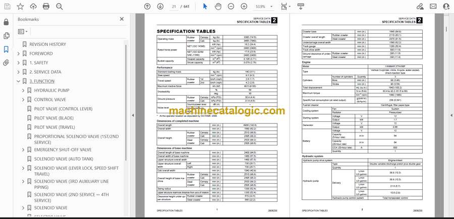
- SPECIFICATION TABLES
- Performance
- Dimensions of completed machine
- Dimensions of base machine
- Engine
- Hydraulic system
- Operating device
- Slew equipment
- Lower machinery
- Working equipment
- Working dimensions
- Main structure
- Hydraulic cylinder
- Digging force
- Blade
- TABLE OF MASSES
- Upper structure
- Lower structure
- Attachments
- LUBRICANT AND FUEL CHART
- PERFORMANCE CRITERIA
- Standard values table
- Hydraulic pump assignment table
- Hydraulic pump No. P1
- Hydraulic pump No. P2
- Hydraulic pump No. P3
- Hydraulic pump No. P4
- Methods for inspecting performance
- 1. Engine speed
- 2. Hydraulic oil pressure
- 3. Cylinder operating speed
- 4. Slew speed (2 rotations)
- 5. Overrun when slewing stops
- 6. Natural travel drop (Over 5 min.)
- 7. Natural slew drop (Over 5 min.)
- 8. Travel speed (10 m (32.8 ft))
- 9. Travel speed (5 revolutions)
- 10. Straight-ahead traveling (10 m (32.8 ft))
- 11. Straight travel function check
- 12. Natural cylinder drop
- 13. Backlash
- 14. Lever play
- 15. Crawler tension
- 16. Blade levelness
- 17. Blade height
- 18. Slew bearing play
- TIGHTENING TORQUE
- Hydraulic hose
- Bite-type pipe fitting for steel pipe
- Joint for piping
- Joint for piping (O-ring seal type)
- Bolts and nuts (JIS strength category 10.9)
- HYDRAULIC CIRCUIT DIAGRAM
- 3rd service hard lock specification
- ELECTRICAL CIRCUIT DIAGRAM
- Symbols in electrical circuit diagram
- Wire color symbols
- Wire color table
- Wire types
- Schematic diagram
- Cab
- Serial No.: 123600005 to 123600844
- Serial No.: 123600845 to 123601670
- Serial No.: 123601671 to 123602338
- Serial No.: 123602339 to 123602563
- Serial No.: 123602564 to 123602949
- Serial No.: 123602950 to 123603458
- Serial No.: 123603459 to 123606697
- Serial No.: 123606698 or later
- Canopy
- Serial No.: 123600005 to 123600844
- Serial No.: 123600845 to 123601057
- Serial No.: 123601058 to 123601670
- Serial No.: 123601671 to 123602338
- Serial No.: 123602339 to 123602563
- Serial No.: 123602564 to 123602949
- Serial No.: 123602950 to 123603458
- Serial No.: 123603459 or later
- HYDRAULIC DEVICE LAYOUT DIAGRAM
- 3. FUNCTION
- HYDRAULIC PUMP
- Constant horsepower control
- Power shift mode (reduced horsepower control by P3 pressure)
- Engine load factor mode (reduced horsepower control by Pc pressure)
- CONTROL VALVE
- Overview
- Standard specification
- Angle blade specification
- 2nd service/3rd service/angle blade specification
- Operation
- Bucket
- Boom
- P1 travel
- P1 and P2 inlets
- P2 travel
- Arm
- Swing
- 1st service
- Slew
- Blade
- 2nd service
- Angle blade
- Communication valve
- Main relief valve
- Overload relief valve
- Anti-cavitation valve
- PILOT VALVE (CONTROL LEVER)
- PILOT VALVE (BLADE)
- PILOT VALVE (TRAVEL)
- PROPORTIONAL SOLENOID VALVE (1ST/2ND SERVICE)
- EMERGENCY SHUT-OFF VALVE
- Neutral (Positions maintained)
- Boom cylinder raising and arm cylinder dumping operations
- Boom cylinder lowering and arm cylinder excavator operations
- Relief valve operation (When an abnormal high pressure is produced in the cylinder)
- SOLENOID VALVE (AUTO TANK)
- SOLENOID VALVE (LEVER LOCK, SPEED SHIFT TRAVEL)
- Solenoid switching/relief function
- When not energized
- When energized
- Check function
- SOLENOID VALVE (3RD AUXILIARY LINE PIPING)
- SOLENOID VALVE (2ND SERVICE ↔ 4TH SERVICE)
- SOLENOID VALVE
- SELECTOR VALVE
- CYLINDER (BOOM, ARM, BUCKET, SWING)
- Function
- Function of each part
- Seal system components: Bushing (4), rod packing (5), dust seal (6)
- Piston assembly
- Operation
- TRAVEL MOTOR
- Hydraulic motor
- Counter balance valve
- 2-speed mechanism
- 2nd speed control valve
- Swash plate
- Automatic 2-speed switching system
- Parking brake
- Reduction gears
- SLEW MOTOR
- Hydraulic motor
- Relief valve
- The 1st stage
- The 2nd stage
- Make-up valve
- Anti-rebound valve
- When the brake is actuated
- When the Motor Rebounds
- Parking brake
- Timer valve
- Reduction gears
- SWIVEL JOINT
- 4. DISASSEMBLY AND ASSEMBLY
- SERVICE STANDARDS
- Carrier roller
- Track roller
- Sprocket
- Idler
- Clearance for pin and bushing
- Replacing the pin and bushing
- DRIVE SYSTEM
- Engine
- Radiator
- Construction diagram
- Removing the engine
- Installing the engine
- Hydraulic pump
- Construction diagram
- Removing the hydraulic pump
- Installing the hydraulic pump
- Fuel tank
- Construction diagram
- Removing the fuel tank
- Installing the fuel tank
- Fuel filler pump
- Battery
- Construction diagram
- Removing the battery
- Installing the battery
- TRAVEL SYSTEM
- Track roller
- Carrier roller
- Front idler
- Grease cylinder assembly
- Travel motor
- Shoe guide
- Construction diagram
- Removing the rubber crawler
- Installing the rubber crawler
- Removing a steel crawler
- Installing a steel crawler
- Replacing the crawler
- Removing the carrier roller
- Installing the carrier roller
- Removing the track roller
- Installing the track roller
- Removing the idler and grease cylinder assembly
- Installing the idler and grease cylinder assembly
- Removing the travel motor
- Installing the travel motor
- SLEW EQUIPMENT
- Slew motor
- Construction diagram
- Removing the slew motor
- Installing the slew motor
- Slew bearing
- Construction diagram
- Removing the slew bearing
- Installing the slew bearing
- Swivel joint
- Construction diagram
- Removing the swivel joint
- Installing the swivel joint
- UPPER FRAME
- Upper frame
- Grease piping
- Construction diagram
- Removing the upper frame
- Installing the upper frame
- Covers
- Construction diagram
- Removing the covers
- Attaching the covers
- Cab mounting assembly
- Cab interior assembly
- Cab switch assembly
- Canopy mounting assembly
- Canopy switch assembly
- Floor frame assembly
- Operator seat assembly
- Radio assembly
- Construction diagram
- Removing the cab
- Installing the cab
- Removing the canopy
- Installing the canopy
- Removing the glass window panes
- Installing the glass window panes
- OPERATING DEVICE
- Construction diagram
- Travel lever
- Blade lever
- Valve bracket (R)
- Valve bracket (L)
- Control box (L)
- Control box (R) cab
- Control box (R) canopy
- Pilot valves
- Control lever piping type A (ISO) – Type G (JCB)
- Disassembly and assembly
- Removal and installation of the accumulator
- WORK EQUIPMENT
- Construction diagram
- Arm assembly
- Bucket assembly
- Boom assembly
- Boom swing assembly
- Dozer blade assembly
- Dozer blade assembly (angle blade type)
- Disassembly and assembly
- Removal and installation of the bucket
- Removal and installation of the bucket link
- Releasing residual pressure
- Removal and installation of the arm
- Removal and installation of the boom
- Removal and installation of the swing bracket
- Removal and installation of the dozer blade
- HYDRAULIC TANK
- Hydraulic tank assembly
- Construction diagram
- Removing the hydraulic tank
- Installing the hydraulic tank
- Inspecting and refilling the oil in the hydraulic tank
- Bleeding off the air
- HYDRAULIC PUMP
- Construction diagram
- Disassembly and assembly
- Disassembly
- Assembly
- Inspection and adjustments
- CONTROL VALVE
- Construction diagram
- Main relief valve
- Overload relief valve
- Anti-cavitation valve
- Disassembly
- General precautions
- Disassembly
- Valve assembly
- Boom section
- Coupling valve
- Main relief valve
- Inspection and adjustments
- PILOT VALVE
- Construction
- Special tools
- Installation jig A
- Installation jig B
- Disassembly and Assembly
- Inspection and adjustment
- PILOT VALVE (SWING, BLADE)
- Construction
- Special Jigs
- Disassembly and Assembly
- Inspection and adjustment
- PILOT VALVE (TRAVEL)
- Construction diagram
- Disassembly and Assembly
- General precautions
- Special Jigs
- Disassembly
- Assembly
- Inspection and adjustment
- PROPORTIONAL SOLENOID VALVE (1ST/2ND SERVICE)
- Construction
- Disassembly and Assembly
- Inspection and adjustment
- EMERGENCY SHUTOFF VALVE
- SOLENOID VALVE (ANGLE BLADE)
- Construction
- Disassembly and Assembly
- Inspection and adjustment
- SOLENOID VALVE (BLADE FLOAT)
- Construction
- Disassembly and Assembly
- Inspection and adjustment
- SOLENOID VALVE (3RD AUXILIARY LINE PIPING)
- Construction
- Disassembly and Assembly
- Inspection and adjustment
- SOLENOID VALVE (LEVER LOCK)
- Construction
- Disassembly
- Solenoid valve
- Relief valve
- Check valve
- Assembly
- Inspection and adjustment
- SOLENOID VALVE (4TH AUX)
- Construction
- Disassembly and Assembly
- Inspection and adjustment
- SOLENOID VALVE (AUTO TANK)
- Construction
- Disassembly and Assembly
- Inspection and adjustments
- SELECTOR VALVE
- Construction
- Disassembly and Assembly
- Inspection and adjustment
- CYLINDER
- Boom cylinder
- Boom cylinder (with emergency shut-off valve)
- Arm cylinder
- Arm cylinder (with emergency shut-off valve)
- Bucket cylinder
- Swing cylinder
- Blade cylinder
- Angle cylinder
- Disassembly and assembly
- Service standards
- Inspection after assembly
- Tools required
- Special jigs
- Disassembly
- Assembly
- TRAVEL MOTOR
- Construction
- Hydraulic motor
- Reduction gears
- Counterbalance valve, 2nd-speed control valve, relief block assembly
- Assembly
- Counter balance valve and hydraulic motor
- Reduction gears
- Inspection and adjustment
- SLEW MOTOR
- Construction
- Hydraulic motor
- Reduction gears
- Brake valve
- Special tools
- Disassembly
- Slew motor
- Brake valve and hydraulic motor
- Reduction gears
- Anti-rebound valve
- Assembly
- Anti-rebound valve
- Brake valve and hydraulic motor
- Reduction gears
- Slew motor
- Inspection and adjustment
- SWIVEL JOINT
- Construction
- Disassembly and Assembly
- Inspection and adjustment
- Inspection procedures and remedial actions
- Use limit for parts
- Inspection after assembly
- WIRE HARNESS
- Electrical wiring assembly (cab specification): 03642-00000-02 (Page 1 of 3)
- Floor wiring assembly: 03642-00005-03
- Electrical wiring assembly (cab specification): 03642-00000-02 (Page 2 of 3)
- Body wiring assembly: 03642-00006-02
- Electrical wiring assembly (cab specification): 03642-00000-02 (Page 3 of 3)
- Wire harness: 03742-00076-00
- Wire harness: 03742-00076-00
- Wire harness: 05542-00046-01
- Electrical wiring assembly (canopy specification): 03642-00001-01 (Page 1 of 3)
- Floor wiring assembly: 03642-00007-03
- Electrical wiring assembly (canopy specification) 03642-00001-01 (Page 2 of 3)
- Body wiring assembly: 03642-00006-02
- Electrical wiring assembly (canopy specification) 03642-00001-01 (Page 3 of 3)
- Floor wiring: 03742-00078-01
- Body wiring assembly: 03642-00006-02
- Wire harness: 03642-00003-04
- Switch harness (cab specification): 03642-00045-01
- Switch harness (canopy specification): 03642-00044-01
- Travel alarm: 03642-00004
- GPS unit assembly
- Cab harness
- Wire harness: 03586-00082-01
- Wire harness: 05686-60590-00
- 5. TROUBLESHOOTING
- TROUBLESHOOTING
- Notes on the malfunction diagnosis and repair
- GENERAL
- The engine does not start.
- 1. Did any error code occur?
- 2. Does the starter motor rotate?
- 3. Is there enough fuel?
- 4. Is the fuel filter clogged?
- The engine speed cannot be increased.
- 1. Did any error code occur?
- All the attachments and travel motors are inoperable.
- 1. Did any vehicle error code occur?
- 2. Is the hydraulic oil above the specified amount?
- 3. Is the pilot pressure within the standard value range?
- 4. Is the main pressure within the standard value range?
- All the attachments and travel motors are operable but are slow.
- 1. Does the engine speed reach the maximum?
- 2. Is the hydraulic oil above the specified amount?
- 3. Is abnormal sound coming from the hydraulic pump?
- 4. Is the pilot pressure within the standard value range?
- 5. Is the main pressure within the standard value range?
- TRAVEL
- The travel motors are inoperable (both left and right or one of them).
- 1. Do hydraulic devices other than the travel motor operate?
- 2. Is the discharge pressure from the pilot valve (for travel operation) normal?
- 3. Is the discharge pressure from the control valve (travel section) normal?
- 4. Is the discharge pressure from the swivel joint normal?
- The vehicle veers to one side with the left or right travel speed slowing down when it travels forward or backward.
- 1. Is the tension of the crawler normal?
- 2. Is any foreign matter trapped in the crawler?
- 3. Is the discharge pressure from the pilot valve (for travel operation) normal?
- 4. Is the discharge pressure from the control valve (travel section) normal?
- 5. Is the discharge pressure from the swivel joint normal?
- The travel speed cannot be changed.
- 1. Is the voltage applied to the solenoid valve (for variable travel speed)?
- 2. Is the variable travel speed pressure from the solenoid valve (for variable travel speed) normal?
- 3. Is the variable travel speed pressure (pilot pressure) from the swivel joint normal?
- SLEW
- The vehicle cannot slew.
- 1. Do hydraulic devices other than the slew operate?
- 2. Is the slew pressure within the standard value range?
- 3. Is the hydraulic piping that supplies the slew brake release pressure abnormal?
- 4. Does the slew bearing rotate?
- 5. Is the discharge pressure from the pilot valve (for slew operation) normal?
- 6. Is the discharge pressure from the control valve (slew section) normal?
- The vehicle cannot slew to the left or right.
- 1. Is the slew pressure within the standard value range?
- 2. Is the hydraulic piping that supplies the slew brake release pressure abnormal?
- 3. Is the discharge pressure from the pilot valve (for slew operation) normal?
- 4. Is the discharge pressure (main pressure) from the control valve (slew section) normal?
- 5. Is the slew relief valve normal?
- The vehicle can slew but is slow and less powerful.
- 1. Do hydraulic devices other than the slew operate normally?
- 2. Is the slew pressure below the standard value range?
- 3. Is the slew relief valve or relief valve seat abnormal?
- 4. Is the discharge pressure from the pilot valve (for slew operation) normal?
- 5. Is the discharge pressure from the control valve (slew section) normal?
- The slewing stop flow amount is large or the vehicle cannot stop.
- 1. Is the slew pressure below the standard value range?
- 2. Can the pilot valve (for slew operation) be in the neutral status?
- 3. Can the control valve (slew section) be in the neutral status?
- BOOM
- The boom cannot rise or drop.
- 1. Do hydraulic devices other than the boom operate?
- 2. Is the discharge pressure from the pilot valve (for boom operation) normal?
- 3. Is the discharge pressure from the control valve (boom section) normal?
- The boom can rise and drop but is slow and less powerful.
- 1. Do hydraulic devices other than the boom operate normally?
- 2. Is the discharge pressure from the pilot valve (for boom operation) normal?
- 3. Is the discharge pressure from the control valve (boom section) normal?
- 4. Is the boom cylinder internally leaking?
- The boom drops temporarily when the boom control lever is slowly pulled.
- 1. Is the boom cylinder internally leaking?
- The amount of boom natural drop is large.
- 1. Is the boom cylinder internally leaking?
- 2. Is the boom emergency shutoff valve internally leaking?
- ARM
- The arm cannot be pushed or pulled.
- 1. Do hydraulic devices other than the arm operate?
- 2. Is the discharge pressure from the pilot valve (for arm operation) normal?
- 3. Is the discharge pressure from the control valve (arm section) normal?
- The arm can be pushed and pulled but is slow and less powerful.
- 1. Do hydraulic devices other than the arm operate normally?
- 2. Is the discharge pressure from the pilot valve (for arm operation) normal?
- 3. Is the discharge pressure from the control valve (arm section) normal?
- The amount of arm natural drop is large.
- 1. Is the arm emergency shutoff valve internally leaking?
- BUCKET
- The bucket cannot dig or remove the ground.
- 1. Do hydraulic devices other than the bucket operate?
- 2. Is the discharge pressure from the pilot valve (for bucket operation) normal?
- 3. Is the discharge pressure from the control valve (bucket section) normal?
- The bucket can dig and remove the ground but is slow and less powerful.
- 1. Do hydraulic devices other than the bucket operate normally?
- 2. Is the discharge pressure from the pilot valve (for bucket operation) normal?
- 3. Is the discharge pressure from the control valve (bucket section) normal?
- The amount of bucket natural drop is large.
- 1. Is the hydraulic piping connected to the bucket cylinder failing, such as leaking?
- SWING
- The vehicle cannot swing.
- 1. Do hydraulic devices other than the swing operate?
- 2. Is the discharge pressure from the pilot valve (for swing operation) normal?
- 3. Is the discharge pressure from the control valve (swing section) normal?
- The vehicle can swing but is slow and less powerful.
- 1. Do hydraulic devices other than the swing operate normally?
- 2. Is the discharge pressure from the pilot valve (for bucket operation) normal?
- 3. Is the discharge pressure from the control valve (swing section) normal?
- The amount of swing natural drop is large.
- 1. Is the hydraulic piping connected to the swing cylinder failing, such as leaking?
- BLADE
- The blade does not rise or drop.
- 1. Do hydraulic devices other than the blade operate?
- 2. Is the discharge pressure from the pilot valve (for blade operation) normal?
- 3. Is the discharge pressure from the control valve (blade section) normal?
- 4. Is the discharge pressure from the swivel joint normal?
- The blade can rise and drop but is slow and less powerful.
- 1. Do hydraulic devices other than the blade operate normally?
- 2. Is the discharge pressure from the pilot valve (for blade operation) normal?
- 3. Is the discharge pressure (main pressure) from the control valve (blade section) normal?
- 4. Is the discharge pressure (main pressure) from the swivel joint normal?
- The amount of blade natural drop is large.
- 1. Is the hydraulic piping connected to the blade cylinder failing, such as leaking?
- SERVICE
- The attachment connected to the 1st service is inoperable.
- 1. Do hydraulic devices other than the 1st service operate?
- 2. Is the voltage applied to the proportional solenoid valve (for 1st service)?
- 3. Is the pressure on the 1st service A and B within the standard value range?
- 4. Is the discharge pressure from the proportional solenoid valve (for 1st service) normal?
- The attachment connected to the 2nd service is inoperable.
- 1. Do hydraulic devices other than the 2nd service operate?
- 2. Is the voltage applied to the solenoid valve (for 2nd service and 4th service switching)?
- 3. Is the voltage applied to the proportional solenoid valve (for 2nd service)?
- 4. Is the pressure on the 2nd service A and B within the standard value range?
- 5. Is the discharge pressure from the proportional solenoid valve (for 2nd service) normal?
- 6. Is the discharge pressure from the control valve (2nd service section) normal?
- The quick-hitch cannot be locked (3rd service).
- 1. Do hydraulic devices other than the quick-hitch operate?
- 2. Is the pressure on the 3rd service A normal?
- 3. Is the hydraulic piping connected to the 3rd service A failing?
- The quick-hitch cannot be unlocked (3rd service).
- 1. Do hydraulic devices other than the quick-hitch operate?
- 2. Is the pressure on the 3rd service B within the standard value range?
- 3. Is the voltage applied to the solenoid valve (for 3rd service)?
- 4. Is the discharge pressure from the solenoid valve (for 3rd service) normal?
- HYDRAULIC PUMP
- PILOT VALVE (TRAVEL)
- PILOT VALVE (OPERATION LEVER, SWING, BLADE)
- SOLENOID VALVE (LEVER LOCK)
- SOLENOID VALVE (3RD SERVICE)
- SOLENOID VALVE (ANGLE BLADE)
- CYLINDER
- SLEW MOTOR
- Slew motor function
- Function of motor internal valve
- Parking brake and hydraulic pressure timer function
- SWIVEL JOINT
- 6. OTHER
- MAINTENANCE SOFTWARE MANUAL
- CONTENTS
- 1. OUTLINE
- 2. CONNECTION METHODS
- 2-1. Items needed
- 2-2. Installation method
- 2-2-1. Installation of the PLUS+1 Service Tool
- 2-2-2. Installation of the maintenance tool driver
- 2-3. Connection to the machine and startup of the maintenance software
- 3. DESCRIPTION OF FUNCTIONS
- 3-1. Home (Main screen)
- 3-2. Machine status
- Inputs
- Outputs
- CAN
- Feedback
- Error Code
- Vehicle status
- 3-3. Engine status
- 3-4. AUX1
- AUX1
- Grip setting
- Stroke setting
- Current setting
- 3-5. AUX2_AUX4
- AUX2_AUX4
- Grip setting
- Stroke setting
- Current setting
- 3-6. Other
- Lift alarm
- Misc
- Option
- Pattern Change
- Immobilizer
- Hourmeter man
- Engine auto stop
- AIR CONDITIONER
- [1] Product Overview
- 1. Outline
- 2. Specifications
- [2] Operating and Handling the Air Conditioner
- 1. Outlets and controls
- 2. Controls
- 3. Operation Guidelines
- 4. Air Conditioner Use and Precautions
- 5. Handling the Air Conditioner
- [3] Construction, Operation and Control
- 1. Construction
- 2. Air Conditioner Operation and Control
- [4] Inspection and Maintenance
- 1. Air Conditioner Inspection and Maintenance Table
- 2. Air Conditioner Daily Inspections and Handling Procedures
- 3. Maintenance
- [5] Refrigerant Charging
- 1. Safety Precautions when Charging Refrigerant
- 2. Evacuation
- 3. Refrigerant charging
- [6] Troubleshooting
- 1. Troubleshooting using a Gauge Manifold
- 2. Troubleshooting Table
- VEHICLE ERROR CODES
- Diagnostics procedures for malfunctions and failure
- Repair procedures
- How to check the detection ports
- TABLE OF VEHICLE ERROR CODES
- TABLE OF ENGINE ERROR CODES
Takeuchi


