Takeuchi TB285 Hydraulic Excavator Workshop Manual (CM1E014) (SN 185000001-)
The TB285 usually spends its life loading trucks, trenching utilities, and working around tight jobsites where downtime hurts. This workshop manual is what I’d pull out when I need a clear, step‑by‑step path to strip, inspect, and correctly reinstall major components without guesswork. For example, if the boom drifted down overnight or the swing felt sloppy, I’d use this book to trace the fault through the hydraulic circuit, verify clearances, and make sure everything goes back together torqued and aligned the way Takeuchi intended.
Applications & Use Cases
- Planning a major repair on the boom, arm, or undercarriage so you follow the proper removal and reinstallation sequence.
- Tracing hydraulic issues like weak travel, slow functions, or cylinder creep by methodically checking components in a logical order.
- Inspecting wear points during scheduled maintenance and knowing when pins, bushings, or seals should be replaced instead of reused.
- Verifying adjustments after replacing pumps, motors, or control valves so the machine responds correctly and safely.
- Confirming routing and clamping of hoses, harnesses, and lines to prevent chafing and future leaks.
FAQ
Q: Can I keep this manual on a tablet in the field?
A: Yes, it’s practical to use on a tablet or laptop; you can zoom diagrams and keep it next to the machine while you work.
Q: Is it worth printing sections of this manual?
A: Many techs print just the procedures they’re doing that day, so greasy hands don’t ruin the device and you can mark notes as you go.
Safety Note
Always lock out, support, and relieve hydraulic pressure exactly as described before loosening any component.
Takeuchi TB285 Hydraulic Excavator Index:
- REVISION HISTORY
- FOREWORD
- Directional terms: front, rear, left, right
- Machine serial number
- Symbols used in this manual
- Manual structure
- 1 SAFETY
- SAFETY ALERT SYMBOL
- SAFETY PRECAUTIONS
- Observe all safety rules
- Wear safe clothing and protective gear
- Install an extinguisher and a first aid kit
- Lockout/Tagout (LOTO)
- Use the correct tools
- Regularly replace the safety-critical parts
- Explosionproof lighting
- Prohibit access by unauthorized persons
- Prepare the work area
- When the canopy is tilted up
- Keep the machine clean
- Stop the engine before performing maintenance
- Keep clear of the moving fan and belt
- When working under the machine
- When working on the machine
- Securing the working equipment
- Secure the engine hood and guard when they are open
- Place heavy components in a stable position
- Caution when filling with fuel or oil
- Handling of hoses
- Be careful with hot and pressurized components
- Handling of radiator
- Be careful with oils under pressure
- Release the residual pressure from the hydraulic system before performing maintenance
- Be careful with grease under pressure
- Handling of the accumulator
- Disconnect the battery
- Use caution when handling batteries
- Have a service agent repair welding cracks or other damage
- Checks after maintenance
- Disposing of wastes
- CAUTIONS WHEN WORKING
- Before starting work
- When disassembling or assembling
- When removing/installing the hydraulic unit
- When connecting/disconnecting the hoses or pipes
- Handling of seals
- Pressure adjustment for hydraulic devices
- 2 SERVICE DATA
- DIMENSIONAL DRAWING
- Machine dimensions
- Operating range
- SPECIFICATION TABLES
- Performance
- Machine dimensions
- Dimensions of base machine
- Engine
- Hydraulic system
- Operating device
- Slew equipment
- Lower machinery
- Working equipment
- Working dimensions (Standard arm)
- Main structure
- Hydraulic cylinder
- Digging force
- Dozer blade
- LUBRICANT AND FUEL CHART
- PERFORMANCE CRITERIA
- Standard values table
- 185000001 to 185000167
- From 185000168
- Hydraulic pump assignment table
- Methods for inspecting performance
- Hydraulic oil pressure (Main relief valve set pressure)
- Travel speed (5 revolutions)
- Travel speed (10 m)
- Straight-ahead traveling
- Natural travel drop
- Slew time
- Overrun when slewing stops
- Natural slew drop
- Boom cylinder speed
- Arm cylinder speed
- Bucket cylinder speed
- Dozer blade cylinder speed
- Swing cylinder speed
- Natural cylinder drop
- Swing cylinder
- Lever play
- Backlash
- Slew bearing play
- Crawler tension
- TIGHTENING TORQUE
- Hydraulic hose
- Bite-type pipe fitting for steel pipe
- Joint for piping
- Joint for piping (O-ring seal type)
- Bolts and nuts (JIS strength category 10.9)
- HYDRAULIC CIRCUIT DIAGRAM
- Mono-boom specification
- Serial No.: 185000003 to 185000891
- Serial No.: 185000892 to 185001141
- Serial No.: 185001142 to 185001471
- Serial No.: 185001472 to 185001544
- 185001545 or later
- 3rd service hard lock specification
- Two-piece boom specification (two-cylinder type)
- Serial No.: 185000003 to 185001471
- Serial No.: 185001472 or later
- Two-piece boom specification (one-cylinder type)
- Serial No.: 185000003 to 185000913
- Serial No.: 185000914 to 185001141
- Serial No.: 185001142 to 185001518
- Serial No.: 185001519 to 185001657
- Serial No.: 185001658 or later
- ELECTRICAL CIRCUIT DIAGRAM
- Symbols in electrical circuit diagram
- Wire color symbols
- Wire color table
- Wire types
- Schematic diagram
- Serial No.: 185000002 to 185000008
- Serial No.: 185000009 to 185000778
- Serial No.: 185000779 to 185001686
- Serial No.: 185001687 to 185001847
- Serial No.: 185001848 or later
- Wire harness diagram
- 3 FUNCTION
- Hydraulic pump
- Gear pump
- Control valve (main)
- Control valve (for slew)
- PILOT VALVE (CONTROL LEVER)
- Pilot valve (swing)
- Pilot valve (blade)
- PILOT VALVE (TRAVEL)
- PROPORTIONAL SOLENOID VALVE (1ST SERVICE / 2ND SERVICE)
- EMERGENCY SHUTOFF VALVE
- EMERGENCY SHUTOFF VALVE
- Spool at the neutral position
- When oil flows from port A to port B
- When oil flows from port B to port A
- When an abnormal high pressure is produced in the cylinder
- EMERGENCY SHUTOFF VALVE
- Spool at the neutral position
- When oil flows from port A to port B
- When oil flows from port B to port A
- When an abnormal high pressure is produced in the cylinder
- Solenoid valve
- SELECTOR VALVE
- Reducing valve
- Cylinders
- Travel motor
- Slew motor
- SWIVEL JOINT
- 4 DISASSEMBLY AND ASSEMBLY
- Service standards
- Drive system
- Travel system
- Slew equipment
- Upper frame
- Operating device
- Attachments
- HYDRAULIC TANK
- Removing the hydraulic tank
- Installing the hydraulic tank
- Hydraulic pump
- GEAR PUMP
- Construction
- Disassembly and Assembly
- Inspection and adjustment
- Checking the parts
- Test operation
- Measuring the discharge volume
- Control valve
- PILOT VALVE
- Construction
- Special tools
- Installation jig A
- Installation jig B
- Disassembly and Assembly
- Inspection and adjustment
- Pilot valve (swing, blade)
- Pilot valve (travel)
- Proportional control solenoid valve
- EMERGENCY SHUTOFF VALVE
- Solenoid valve (lever lock, speed shift)
- SOLENOID VALVE (LEVER LOCK)
- Construction
- Disassembly
- Solenoid valve
- Relief valve
- Check valve
- Assembly
- Inspection and adjustment
- SOLENOID VALVE (ANGLE BLADE)
- Construction
- Disassembly and Assembly
- Inspection and adjustment
- SOLENOID VALVE (BLADE FLOAT)
- Construction
- Disassembly and Assembly
- Inspection and adjustment
- Solenoid valve (4th auxiliary line piping)
- Solenoid valve (Auxiliary line piping switching)
- SELECTOR VALVE
- Construction
- Disassembly and Assembly
- Inspection and adjustment
- REDUCING VALVE
- Construction
- Disassembly and assembly
- Inspection and adjustment
- Checking the parts
- Pressure adjustment
- CYLINDERS
- Construction
- Boom cylinder
- Arm cylinder
- Bucket cylinder
- Dozer blade cylinder
- Swing cylinder
- Disassembly and Assembly
- Special tools
- Disassembly
- Assembly
- Inspection and adjustment
- Inspection after disassembly
- Inspection after assembly
- Tensioning cylinder
- TRAVEL MOTOR
- Construction
- Disassembly and assembly
- Disassembly
- Assembly
- Inspection and adjustment
- Performance Verification Testing
- Slew motor
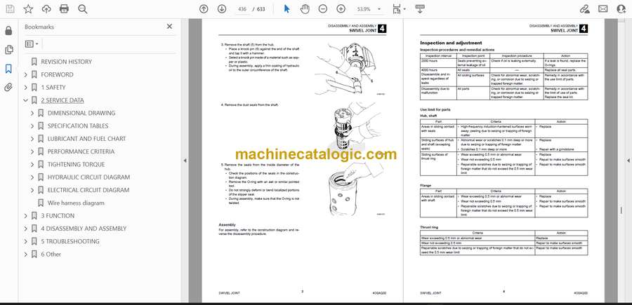
- SWIVEL JOINT
- Construction
- Disassembly and Assembly
- Inspection and adjustment
- Inspection procedures and remedial actions
- Use limit for parts
- Inspection after assembly
- 5 TROUBLESHOOTING
- Notes on troubleshooting and servicing
- Overall machine
- Traveling
- Shoe tension
- Slewing
- Boom
- Arm
- Bucket
- Boom swing
- Blade
- Auxiliary hydraulics
- Angle blade
- HYDRAULIC PUMP
- Gear pump
- Control valve
- Pilot valve
- Solenoid valve
- Cylinders
- Travel motor
- SLEW MOTOR
- Hydraulic motor, brake valve
- Parking brake
- 6 Other
- Airconditioner (TB285/TB290)
- How to change the lever switch pattern
- Maintenance Software Manual
- Vehicle Error Codes
- Error Codes
Takeuchi


