Takeuchi TB290 Hydraulic Excavator Workshop Manual (CM3E026) (SN 185100001-)
The TB290 usually lives in the dirt—trenching, loading trucks, working around utilities—often in tight, rough sites. This workshop manual is what I’d grab when I need the exact sequence to strip, inspect, and correctly reinstall major components without guesswork. If, for example, the boom drifts down under load, this book walks me through how to trace that fault through the hydraulic system, verify what’s worn, and button it back up safely.
Applications & Use Cases
- Planning a major repair on the boom, arm, or swing system with clear step-by-step removal and reinstallation checks.
- Tracing hydraulic issues like slow functions or weak travel by following the recommended diagnostic flow instead of random part-swapping.
- Inspecting wear points on pins, bushings, and cylinders using the manual’s guidance on what to look and feel for.
- Rebuilding key components (motors, pumps, final drives) while keeping track of orientation, shims, and seals during reassembly.
- Verifying adjustments after repairs so travel, slew, and work groups run smooth and don’t fight each other.
FAQ
Q: Can I use this manual on a tablet in the field?
A: Yes, it’s practical to keep it on a tablet or laptop so you can zoom diagrams and search quickly while standing by the machine.
Q: Is it worth printing sections?
A: I usually print just the procedures I’m doing that day, so I can mark notes and keep greasy hands off my device.
Safety Note
Always follow the manual’s support, lockout, and pressure-relief steps before loosening any hydraulic or structural component.
Takeuchi TB290 Hydraulic Excavator Index:
- REVISION HISTORY
- FOREWORD
- Directional terms: front, rear, left, right
- Machine serial number
- Symbols used in this manual
- Manual structure
- 1. SAFETY
- SAFETY ALERT SYMBOL
- SAFETY PRECAUTIONS
- Observe all safety rules
- Wear safe clothing and protective gear
- Install an extinguisher and a first aid kit
- Lockout/Tagout (LOTO)
- Use the correct tools
- Regularly replace the safety-critical parts
- Explosionproof lighting
- Prohibit access by unauthorized persons
- Prepare the work area
- When the canopy is tilted up
- Keep the machine clean
- Stop the engine before performing maintenance
- Keep clear of the moving fan and belt
- When working under the machine
- When working on the machine
- Securing the working equipment
- Secure the engine hood and guard when they are open
- Place heavy components in a stable position
- Caution when filling with fuel or oil
- Handling of hoses
- Be careful with hot and pressurized components
- Handling of radiator
- Be careful with oils under pressure
- Release the residual pressure from the hydraulic system before performing maintenance
- Be careful with grease under pressure
- Handling of the accumulator
- Disconnect the battery
- Use caution when handling batteries
- Have a service agent repair welding cracks or other damage
- Checks after maintenance
- Disposing of wastes
- CAUTIONS WHEN WORKING
- Before starting work
- When disassembling or assembling
- When removing/installing the hydraulic unit
- When connecting/disconnecting the hoses or pipes
- Handling of seals
- Pressure adjustment for hydraulic devices
- 2. SERVICE DATA
- DIMENSIONAL DRAWING
- Machine dimensions
- Operating range
- SPECIFICATION TABLES
- Performance
- Machine dimensions
- Dimensions of base machine
- Engine
- Hydraulic system
- Operating device
- Slew equipment
- Lower machinery
- Working equipment
- Working dimensions (Standard arm)
- Main structure
- Hydraulic cylinder
- Digging force
- Dozer blade
- TABLE OF MASSES
- Upper structure
- Lower structure
- Hoe attachments
- LUBRICANT AND FUEL CHART
- PERFORMANCE EVALUATION STANDARD
- Table of standard values (Serial No.: 185100001 to 185100472)
- Table of standard values (Serial No.: 185100473 to 185101521)
- Table of standard values (Serial No.: 185101522 to 185103985)
- Table of standard values (Serial No.: 185103986 or later)
- Table of standard values (Serial No.: 185108044, 185108550, 185108676 or later)
- Hydraulic pump assignment table
- Control valve TYPE A
- Control valve TYPE B
- Performance inspection guideline
- 1. Engine speed
- 2. Hydraulic pressure
- 3. Cylinder operating speed
- 4. Slew speed (two turns)
- 5. Slewing stop overrun
- 6. Five-minute natural travel drop
- 7. Five-minute natural slew drop
- 8. Travel speed (10 m (32.8 ft))
- 9. Travel speed (five rotations)
- 10. Straight-ahead travel (10 m (32.8 ft))
- 11. Straight-ahead travel function check
- 12. Amount of natural cylinder drop
- 13. Backlash
- 14. Lever play
- 15. Crawler tension
- 16. Blade levelness
- 17. Blade height
- 18. Service flow rate
- 19. Slew bearing play
- TIGHTENING TORQUE
- Hydraulic hose
- Bite-type pipe fitting for steel pipe
- Joint for piping
- Joint for piping (O-ring seal type)
- Bolts and nuts (JIS strength category 10.9)
- HYDRAULIC CIRCUIT DIAGRAM
- Mono-boom specification
- For Austria
- Serial No.: 185100001 to 185101329
- Serial No.: 185101330 to 185102921
- Serial No.: 185102922 to 185103839
- Serial No.: 185103840 to 185106159
- Serial No.: 185106160 to 185107041
- Serial No.: 185107042 or later
- For Germany and the Netherlands
- Serial No.: 185100001 to 185101329
- Serial No.: 185101330 to 185102921
- Serial No.: 185102922 to 185106159
- Serial No.: 185106160 to 185107041
- Serial No.: 185107042 or later
- For USA
- Serial No.: 185100001 to 185101329
- Serial No.: 185101330 to 185102921
- Serial No.: 185102922 to 185108675 (excluding 185108044 and 185108550)
- Serial No.: 185108676 to 185110759 (including 185108044 and 185108550)
- Serial No.: 185110760 or later
- 3rd service hard lock specification (applicable range: Serial No.: 185100001 to 185108675)
- Others
- Serial No.: 185100001 to 185101329
- Serial No.: 185101330 to 185102921
- Serial No.: 185102922 or later
- Two-piece boom specification (one-cylinder type)
- For Austria
- Serial No.: 185100001 to 185101329
- Serial No.: 185101330 to 185102062
- Serial No.: 185102063 to 185103839
- Serial No.: 185103840 to 185104394
- Serial No.: 185104395 to 185106159
- Serial No.: 185106160 to 185107041
- Serial No.: 185107042 or later
- For Germany and the Netherlands
- Serial No.: 185100001 to 185101329
- Serial No.: 185101330 to 185102062
- Serial No.: 185102063 to 185102921
- Serial No.: 185102922 to 185104394
- Serial No.: 185104395 to 185106159
- Serial No.: 185106160 to 185107041
- Serial No.: 185107042 or later
- Others
- Serial No.: 185100001 to 185101329
- Serial No.: 185101330 to 185102062
- Serial No.: 185102063 to 185102921
- Serial No.: 185102922 to 185104394
- Serial No.: 185104395 or later
- 3rd service hard lock specification
- Two-piece boom specification (two-cylinder type)
- ELECTRICAL CIRCUIT DIAGRAM
- Symbols in electrical circuit diagram
- Wire color symbols
- Wire color table
- Wire types
- Schematic diagram
- Serial No.: 185100001 to 185102637
- Serial No.: 185102638 to 185104930
- Serial No.: 185104931 to 185105428
- Serial No.: 185105429 to 185105691
- Serial No.: 185105692 to 185106631
- Serial No.: 185106632 to 185107311
- Serial No.: 185107312 to 185108276 (excluding 185108044)
- Serial No.: 185108277 to 185108423
- Serial No.: 185108424 to 185108573
- Serial No.: 185108574 to 185108675 (excluding 185108550)
- Serial No.: 185108676 to 185111127
- Serial No.: 185111128 or later
- WIRE HARNESS
- Electrical wiring assembly (Serial No.: 185100001 to 185108043, 185108045 to 185108549, 185108551 to 185108675)
- Electrical component cover assembly
- Switch panel assembly
- Relay assembly
- Main harness
- Engine harness
- Main unit harness
- Wire harness
- Electrical wiring assembly (Serial No.: 185108044, 185108550, 185108676 or later)
- Electrical component cover assembly
- Switch panel assembly
- Relay assembly
- Main harness
- Engine harness
- Main unit harness
- Wire harness
- HYDRAULIC DEVICE LAYOUT DIAGRAM
- Two-piece boom specification (one-cylinder type)
- Two-piece boom specification (two-cylinder type)
- 3. FUNCTION
- HYDRAULIC PUMP
- Piston pump
- Horsepower control regulator
- Load-sensing regulator
- GEAR PUMP
- MAIN CONTROL VALVE
- Main control valve TYPE 1 specification machine, Mono-boom specification
- Main control valve TYPE 2 specification machine, Mono-boom specification
- MAIN CONTROL VALVE (Serial No.: 185108044, 185108550, 185108676 or later)
- About this documentation
- Functional description, section
- General hydraulic symbol
- Technical data
- Characteristic curves
- Ordering code
- Hydraulic symbols
- Dimensions
- Set-up options
- Line connections
- SUB CONTROL VALVE FOR SLEW
- SUB CONTROL VALVE FOR 2ND SERVICE AND SLEW
- PILOT VALVE (CONTROL LEVER)
- PILOT VALVE (SWING)
- PILOT VALVE (BLADE)
- PILOT VALVE (TRAVEL)
- PROPORTIONAL SOLENOID VALVE (1ST SERVICE / 2ND SERVICE)
- EMERGENCY SHUTOFF VALVE
- EMERGENCY SHUTOFF VALVE
- EMERGENCY SHUTOFF VALVE
- Spool at the neutral position
- When oil flows from port A to port B
- When oil flows from port B to port A
- When an abnormal high pressure is produced in the cylinder
- EMERGENCY SHUTOFF VALVE
- Spool at the neutral position
- When oil flows from port A to port B
- When oil flows from port B to port A
- When an abnormal high pressure is produced in the cylinder
- SOLENOID VALVE
- Solenoid valve
- Relief valve
- SOLENOID VALVE (3RD SERVICE HARD LOCK)
- SELECTOR VALVE
- REDUCING VALVE
- CYLINDERS
- TRAVEL MOTOR
- Hydraulic motor
- Brake valve
- Relief valve
- 2-speed switching system
- Parking brake
- Reduction gears
- SLEW MOTOR
- Hydraulic motor
- Relief valves
- Make-up valve
- Parking brake
- Timer valve
- Reduction gears
- SWIVEL JOINT
- 4. DISASSEMBLY AND ASSEMBLY
- SERVICE STANDARDS
- Carrier roller
- Track roller
- Sprocket
- Idler
- Clearance for pin and bushing
- DRIVE SYSTEM
- Engine
- Removing the engine
- Installing the engine
- Hydraulic pump
- Removing the hydraulic pump
- Installing the hydraulic pump
- Fuel tank
- Removing the fuel tank
- Installing the fuel tank
- Fuel filler pump
- Battery
- Removing the battery
- Installing the battery
- TRAVEL SYSTEM
- Removing the crawler
- Installing the crawler
- Removing the steel crawler
- Installing the steel crawler
- Installing/removing the segmented rubber crawler
- Replacing the crawler
- Removing the carrier roller
- Installing the carrier roller
- Removing the track roller
- Installing the track roller
- Removing the track roller (for a steel crawler)
- Installing the track roller (for a steel crawler)
- Removing the guide (for a steel crawler)
- Installing the guide (for a steel crawler)
- Replacement of a rubber crawler to a steel crawler
- Removing the idler and track adjuster
- Installing the idler and the track adjuster
- Removing the travel motor
- Installing the travel motor
- SLEW EQUIPMENT
- Slew motor
- Removing the slew motor
- Installing the slew motor
- Slew bearing
- Removing the slew bearing
- Installing the slew bearing
- Swivel joint
- Standard specifications
- Angle blade specifications
- Removing the swivel joint
- Installing the swivel joint
- UPPER FRAME
- Upper frame
- 1/2
- 2/2
- Removing the upper frame
- Installing the upper frame
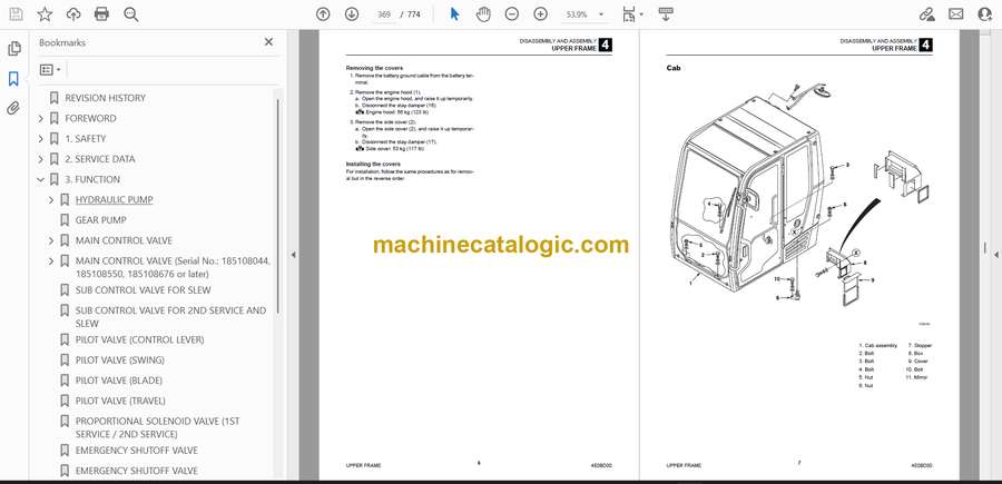
- Covers
- Removing the covers
- Installing the covers
- Cab
- Removing the cab
- Installing the cab
- Replacing glass window panes
- Installing glass window panes
- OPERATING DEVICE
- Construction diagram
- Control lever
- Hydraulic pilot unit
- Main control valve TYPE 1 specification, “Sub control valve for slew” specification
- Main control valve TYPE 1 specification, “Sub control valve for slew” specification
- Main control valve TYPE 1 specification, “Sub control valve for slew” specification
- Main control valve TYPE 2 specification, “Sub control valve for 2nd service and slew” specification
- Main control valve TYPE 2 specification, “Sub control valve for 2nd service and slew” specification
- Main control valve TYPE 2 specification, “Sub control valve for 2nd service and slew” specification
- Main control valve TYPE 2 specification, “Sub control valve for 2nd service and slew” specification
- Blade lever (standard specification)
- Blade lever (angle blade specification)
- Lever stand
- Pilot valve (Left)
- Pilot valve (right)
- Control box (right)
- Disassembly and assembly
- Removal and installation of the accumulator
- WORK EQUIPMENT
- Release of residual pressure
- Hoe attachment
- Blade
- HYDRAULIC TANK
- Removing the hydraulic tank
- Installing the hydraulic tank
- HYDRAULIC PUMP
- Construction
- Disassembly and Assembly
- Inspection
- GEAR PUMP
- Construction
- Disassembly and Assembly
- Inspection and adjustment
- Checking the parts
- Test operation
- Measuring the discharge volume
- CONTROL VALVE
- Main control valve TYPE 1 specification, Mono-boom specification
- Construction diagram, Page 1 of 2
- Construction diagram, Page 2 of 2
- Main control valve TYPE 2 specification (Mono-boom specification)
- Construction diagram
- Swing section
- Right travel section
- Left travel section
- Blade Section
- 2nd service section
- Angle blade section
- Sub control valve for slew
- Sub control valve for 2nd service and slew
- Construction diagram
- Inlet housing
- 2nd service section
- Slew section
- Disassembly and assembly
- Inspection and adjustment
- Checking the parts
- Adjusting pressure of main relief valve
- MAIN CONTROL VALVE (Serial No.: 185108044, 185108550, 185108676 or later)
- 1 Introduction
- 2 Safety instructions
- 2.2 Safety instructions in this document
- 2.3 Symbols
- 4 Fundamental rules
- 4.1 General information concerning control block connection
- 5 Removal / installation of the RS12 control block
- 5.1 General recommendations
- 5.2 Removal of the RS12 control block
- 5.3 Installation of the RS12 control block
- 5.4 Starting, maximal pressure set up
- 6 Inlet element repair procedure
- 6.1 LS pressure relief valve replacement
- 6.2 Plug for the regulating unit replacement
- 6.3 Flow regulator replacement
- 7 Distribution element repair procedure
- 7.1 Secondary valves replacement
- 7.2 Pressure compensator replacement
- 7.3 Check valve replacement
- 7.4 Removal of a spool return via a spring operation A2 Z1
- 7.5 Spool stroke measurement (3 position)
- 7.6 Removal of a hydraulic operation H200 or H230
- 8 Complet control block Disassembly / Assembly
- PILOT VALVE
- Construction
- Special tools
- Installation jig A
- Installation jig B
- Disassembly and Assembly
- Inspection and adjustment
- PILOT VALVE (SWING, BLADE)
- Construction
- Special Jigs
- Disassembly and Assembly
- Inspection and adjustment
- PILOT VALVE (TRAVEL)
- Construction
- Disassembly and Assembly
- Special Jigs
- Disassembly
- Assembly
- Inspection and adjustment
- PROPORTIONAL CONTROL SOLENOID VALVE
- Construction
- Disassembly and Assembly
- Inspection and adjustment
- EMERGENCY SHUTOFF VALVE
- SOLENOID VALVE (LEVER LOCK)
- Construction
- Disassembly
- Solenoid valve
- Relief valve
- Check valve
- Assembly
- Inspection and adjustment
- SOLENOID VALVE (ANGLE BLADE)
- Construction
- Disassembly and Assembly
- Inspection and adjustment
- SOLENOID VALVE (BLADE FLOAT)
- Construction
- Disassembly and Assembly
- Inspection and adjustment
- SOLENOID VALVE (4TH AUXILIARY LINE PIPING)
- Construction
- Disassembly and Assembly
- Inspection and adjustment
- SOLENOID VALVE (AUXILIARY LINE PIPING SWITCHING)
- Construction
- Disassembly and Assembly
- Inspection and adjustments
- SOLENOID VALVE (3RD SERVICE HARD LOCK)
- Construction diagram
- Disassembly and assembly
- Disassembly of solenoid valve
- Assembly of solenoid valve
- SELECTOR VALVE
- Construction
- Disassembly and Assembly
- Inspection and adjustment
- REDUCING VALVE
- Construction
- Disassembly and assembly
- Inspection and adjustment
- Checking the parts
- Pressure adjustment
- CYLINDERS
- Construction
- Boom cylinder
- Arm cylinder
- Bucket cylinder
- Dozer blade cylinder
- Swing cylinder
- Disassembly and Assembly
- Special tools
- Disassembly
- Assembly
- Inspection and adjustment
- Inspection after disassembly
- Inspection after assembly
- TRAVEL MOTOR
- Construction
- Disassembly and assembly
- Disassembly
- Assembly
- Inspection and adjustment
- Performance Verification Testing
- SLEW MOTOR
- Construction
- Special tools
- Installation jig A
- Installation jig B
- Installation jig C
- Installation jig D
- Disassembly and assembly
- Inspection and adjustment
- SWIVEL JOINT
- Construction
- Disassembly and Assembly
- Inspection and adjustment
- Inspection procedures and remedial actions
- Use limit for parts
- Inspection after assembly
- 5. TROUBLESHOOTING
- ABOUT THE TROUBLESHOOTING SECTION
- Notes on troubleshooting and servicing
- OVERALL MACHINE
- No operation is possible.
- All systems working, but insufficient power.
- Boom, bucket, slew and arm fail to move or are too slow.
- TRAVELING
- No right or left travel
- Right or left travel speed decelerates and the machine veers to one side.
- 2nd-speed travel is not possible.
- SHOE TENSION
- No shoe tension or lack of tension.
- SLEW
- The slew operation cannot be performed at all.
- The right or left slew operation cannot be performed.
- The slew operation is slow or lacks power.
- The slewing stop overrun is large or the slew operation cannot be stopped.
- The slew body cannot maintain its attitude when the machine is stopped on sloping ground.
- BOOM
- Boom cylinder does not move.
- Boom cylinder is slow or lacks force.
- When the control lever is pulled slowly, the boom drops temporarily.
- Spontaneous drop of the boom cylinder is too large.
- ARM
- Arm cylinder does not move.
- Arm cylinder is slow or lacks force.
- Spontaneous drop of the arm is too large.
- BUCKET
- Bucket cylinder does not move or lacks force.
- Spontaneous drop of the bucket is too large.
- BOOM SWING
- Swing cylinder does not move.
- BLADE
- Blade cylinder does not move or lacks force.
- The spontaneous drop of the blade is too large, or the blade cannot support the machine.
- AUXILIARY HYDRAULICS
- Prescribed pressure is not supplied to the 1st and 2nd auxiliary lines.
- Prescribed pressure is not supplied to the 3rd and 4th auxiliary lines.
- ANGLE BLADE
- Angle cylinder does not move.
- Angle cylinder lacks force.
- HYDRAULIC PUMP
- GEAR PUMP
- CONTROL VALVE
- MAIN CONTROL VALVE (Serial No.: 185108044, 185108550, 185108676 or later)
- PILOT VALVE
- SOLENOID VALVE
- CYLINDERS
- TRAVEL MOTOR
- Hydraulic motor
- 2nd-speed control
- Parking brake
- SLEW MOTOR
- Hydraulic motor, brake valve
- Parking brake
- 6. OTHER
- MAINTENANCE SOFTWARE MANUAL
- CONTENTS
- 1. OUTLINE
- 2. CONNECTION METHODS
- 2-1. Items needed
- 2-2. Installation of the PLUS+1 GUIDE Service Tool
- 2-3. Installation of the Maintenance Tool driver
- 2-4. Connection to the machine and startup of the Maintenance Software
- 3. DESCRIPTION OF FUNCTIONS
- 3-1. Home (Main screen)
- 3-2. Status
- 3-2-1. Machine status
- 3-2-2. Engine Status
- 3-3. Setting
- 3-3-1. AUX1
- 3-3-2. AUX2
- 3-3-3. Other
- AIR CONDITIONER
- [1] Product Overview
- 1. Outline
- 2. Specifications
- [2] Operating and Handling the Air Conditioner
- 1. Outlets and controls
- 2. Controls
- 3. Operation Guidelines
- 4. Air Conditioner Use and Precautions
- 5. Handling the Air Conditioner
- [3] Construction, Operation and Control
- 1. Construction
- 2. Air Conditioner Operation and Control
- [4] Inspection and Maintenance
- 1. Air Conditioner Inspection and Maintenance Table
- 2. Air Conditioner Daily Inspections and Handling Procedures
- 3. Maintenance
- [5] Refrigerant Charging
- 1. Safety Precautions when Charging Refrigerant
- 2. Evacuation
- 3. Refrigerant charging
- [6] Troubleshooting
- 1. Troubleshooting using a Gauge Manifold
- 2. Troubleshooting Table
- AUTO TANK FUNCTION
- Auxiliary hydraulic piping, 1-way/2-way
- AUTO PRESSURE RELEASE
- Automatic air bleeder vent in the auxiliary hydraulic piping
- 1ST SERVICE/2ND SERVICE PRESSURE ADJUSTMENT METHOD
- Construction diagram
- Relief valve (1st service pressure adjustment)
- Control valve (2nd service pressure adjustment)
- Pressure adjustment method
- 1st service pressure adjustment
- 2nd service pressure adjustment
- LEVER SWITCH PATTERN SWITCHING METHOD
- Applicable models
- Included Parts
- Pattern switching method
- Standard pattern
- Case 1: Reversing the 1st auxiliary line piping and 2nd auxiliary line piping
- Case 2: Reversing A and B around or C and D around
- Case 3: Reversing the 1st auxiliary line piping and 2nd auxiliary line piping and reversing either A and B around or C and D around
- HOW TO ENABLE THE AUX4 FUNCTION
- HOW TO ENABLE THE TWO-PIECE BOOM FUNCTION
- VEHICLE ERROR CODES
Takeuchi


