Takeuchi TB350R Mini Excavator Workshop Manual (CJ6E010) (SN 150200007-)
Out on utility work, landscaping, or tight urban jobs, the TB350R spends its life digging, backfilling, and tracking over rough ground. This workshop manual is what I’d pull out when I’m doing proper repairs, not just quick checks. It walks you through how to strip, inspect, and correctly reinstall major components so the machine tracks straight, swings smooth, and doesn’t come back with the same fault. For example, if the house starts slewing unevenly or drifting, this is the book I’d use to trace the issue, verify clearances, and reassemble the swing gear and hydraulic components without guesswork.
Applications & Use Cases
- Planning a major repair on the undercarriage, boom, or swing system with a clear step‑by‑step sequence.
- Tracing hydraulic faults like weak functions or creeping cylinders and confirming what to test next.
- Inspecting wear points during scheduled services so you don’t miss seals, bushings, or hardware that should be replaced.
- Reinstalling components after teardown and double‑checking alignment, hose routing, and torque patterns.
- Verifying adjustments after control, travel, or attachment work so the machine responds correctly and safely.
FAQ
Q: Can I use this on a tablet in the field?
A: Yes, it works well on a tablet; you can zoom in on diagrams and keep it open next to the machine while you work.
Q: Is it worth printing sections of this manual?
A: I often print the pages for the specific job, mark them with notes or measurements, and keep them in a sleeve to avoid getting them oily.
Safety Note
Always lock out the machine, support raised components securely, and follow the manual’s cautions before loosening any pressurized or heavy parts.
Takeuchi TB350R Mini Excavator Index:
- REVISION HISTORY
- FOREWORD
- Directional terms: front, rear, left, right
- Machine serial number
- Symbols used in this manual
- Manual structure
- 1. SAFETY
- SAFETY ALERT SYMBOL
- SAFETY PRECAUTIONS
- Observe all safety rules
- Wear safe clothing and protective gear
- Install an extinguisher and a first aid kit
- Lockout/Tagout (LOTO)
- Use the correct tools
- Regularly replace the safety-critical parts
- Explosionproof lighting
- Prohibit access by unauthorized persons
- Prepare the work area
- When the canopy is tilted up
- Keep the machine clean
- Stop the engine before performing maintenance
- Keep clear of the moving fan and belt
- When working under the machine
- When working on the machine
- Securing the working equipment
- Secure the engine hood and guard when they are open
- Place heavy components in a stable position
- Caution when filling with fuel or oil
- Handling of hoses
- Be careful with hot and pressurized components
- Handling of radiator
- Be careful with oils under pressure
- Release the residual pressure from the hydraulic system before performing maintenance
- Be careful with grease under pressure
- Handling of the accumulator
- Disconnect the battery
- Use caution when handling batteries
- Have a service agent repair welding cracks or other damage
- Checks after maintenance
- Disposing of wastes
- CAUTIONS WHEN WORKING
- Before starting work
- When disassembling or assembling
- When removing/installing the hydraulic unit
- When connecting/disconnecting the hoses or pipes
- Handling of seals
- Pressure adjustment for hydraulic devices
- 2. SERVICE DATA
- DIMENSIONAL DRAWING
- Machine dimensions
- Work range
- SPECIFICATION TABLE
- Performance
- Completed machine dimensions
- Main unit dimensions
- Engine
- Hydraulic equipment
- Control equipment
- Lighting equipment (attachment position)
- Warning and safety equipment
- Instruments
- Names of parts
- Slew equipment
- Lower machinery
- Power transmission equipment
- Undercarriage
- Working equipment
- Work dimensions
- Main construction
- Hydraulic cylinder
- Digging force
- Blade
- TABLE OF MASSES
- Upper structure
- Lower structure
- Attachments
- TABLE OF FUEL AND LUBRICANT
- PERFORMANCE EVALUATION STANDARD
- Table of standard values
- Table of hydraulic pump assignment
- Hydraulic pump No. P1
- Hydraulic pump No. P2
- Hydraulic pump No. P3
- Hydraulic pump No. P4
- Performance inspection guideline
- 1. Engine speed
- 2. Hydraulic pressure
- 3. Cylinder operating speed
- 4. Slew speed (two turns)
- 5. Slewing stop overrun
- 6. Five-minute natural travel drop
- 7. Five-minute natural slew drop
- 8. Travel speed (10 m (32.8 ft))
- 9. Free rotation speed (five rotations)
- 10. Straight-ahead travel (10 m (32.8 ft))
- 11. Straight-ahead travel function check
- 12. Amount of natural cylinder drop
- 13. Backlash
- 14. Blade levelness
- 15. Blade height
- 16. Service flow rate
- 17. Slew bearing play
- TIGHTENING TORQUE
- Hydraulic hose
- Bite-type pipe fitting for steel pipe
- Joint for piping
- Joint for piping (O-ring seal type)
- Bolts and nuts (JIS strength category 10.9)
- HYDRAULIC CIRCUIT DIAGRAM
- ELECTRICAL CIRCUIT DIAGRAM
- Symbols in electrical circuit diagram
- Wire color symbols
- Wire color table
- Schematic diagram
- Serial No.: 150200007 to 150200078
- Serial No.: 150200079 or later
- Description for the engine start/stop circuit
- Description for the power generation/charging circuit
- Power generation/charging
- WIRE HARNESS
- Electrical wiring assembly
- Main unit wiring assembly
- Main unit harness
- Wire harness
- Canopy wiring assembly
- Electrical wiring assembly
- Main unit wiring assembly
- Main unit harness
- Wire harness
- Cab wiring assembly
- Wire harness
- Wire harness
- Other wire harnesses
- Canopy light assembly
- Wire harness
- Wire harness
- Cab light assembly
- Boom light assembly
- Wire harness
- Wire harness
- Cab sub-assembly
- Wire harness
- Wire harness
- Front sash assembly
- Air conditioner unit assembly
- Harness supplied with engine
- HYDRAULIC DEVICE LAYOUT DIAGRAM
- 3. FUNCTION
- HYDRAULIC PUMP
- Overview
- Pump appearance and ports
- Main structure and functions
- Piston pump
- Operating principle
- CONTROL VALVE
- Overview
- Functions of control valve
- Control in neutral position
- Operation of control valve
- Straight-ahead travel function
- P3 merging function (arm and 1st service)
- Anti-drift valve
- Boom priority circuit
- Auto-idle (AI) signal
- 3rd service (quick-hitch)
- Operations of main sections
- Bucket, left travel, right travel, swing, slew, blade, 2nd service, and angle blade
- Boom
- Arm and 1st service
- 3rd service
- Communication valve
- Anti-cavitation valve
- PILOT VALVE (CONTROL LEVER)
- PILOT VALVE (SWING, BLADE)
- PILOT VALVE (TRAVEL)
- PROPORTIONAL SOLENOID VALVE (1ST SERVICE / 2ND SERVICE)
- EMERGENCY SHUTOFF VALVE
- SOLENOID VALVE (3RD AUXILIARY LINE PIPING)
- SOLENOID VALVE (3RD SERVICE HARD LOCK)
- SOLENOID VALVE (LEVER LOCK, SPEED SHIFT TRAVEL)
- Solenoid switching/relief function
- When not energized
- When energized
- Check function
- SOLENOID VALVE
- SELECTOR VALVE
- PRESSURE REDUCING VALVE
- CYLINDER
- Functions of parts
- Rod cover assembly
- Seal system components: Bushing (4), rod packing (6), dust seal (5)
- Piston assembly
- Operating principle
- CYLINDER
- Functions of parts
- Rod cover assembly
- Seal system configuration: Bushing (4), buffer ring (6), rod packing (7), backup ring (8), dust seal (9)
- Piston assembly
- Operation
- TRAVEL MOTOR
- Reduction gear
- Hydraulic motor (brake valve, parking brake, high/low speed 2-stage switching mechanism)
- SLEW MOTOR
- Hydraulic motor
- Relief valve
- The 1st stage
- The 2nd stage
- Make-up valve
- Anti-rebound valve
- When the brake is actuated
- When the Motor Rebounds
- Parking brake
- Timer valve
- Reduction gears
- SWIVEL JOINT
- 4. DISASSEMBLY AND ASSEMBLY
- SERVICE STANDARD
- Carrier roller
- Track roller
- Sprocket
- Front idler
- Pin
- About replacement of pin and bushing
- DRIVE EQUIPMENT
- Construction diagram
- Assembly of engine
- Engine assembly
- Radiator assembly
- Assembly of hydraulic pump
- Assembly of fuel tank
- Assembly of battery
- Disassembly and assembly
- Removal and installation of the engine
- Removal and installation of the hydraulic pump
- Bleeding air from the hydraulic pump
- Removal and installation of the fuel tank
- Replacement of the fuel tank cap packing
- Removal and installation of the battery
- TRAVEL EQUIPMENT
- Construction diagram
- Assembly of track roller
- Assembly of carrier roller
- Assembly of front idler
- Assembly of grease cylinder
- Assembly of travel motor
- Assembly of lower frame
- Disassembly and assembly
- Removal of the rubber crawler
- Installation of the rubber crawler
- Removal and installation of the carrier roller
- Removal of the track roller
- Installation of the track roller
- Removal and installation of the front idler assembly
- Removal and installation of the travel motor
- SLEW EQUIPMENT
- Construction diagram
- Assembly of slew motor
- Assembly of slew bearing
- Assembly of swivel joint
- Assembly of swivel joint
- Disassembly and assembly
- Removal and installation of the slew motor
- Removal and installation of the slew bearing
- Removal and installation of the swivel joint
- UPPER FRAME
- Construction diagram
- Assembly of main unit
- Assembly of grease piping
- Assembly of cover
- Assembly of cab mounting
- Assembly of canopy mounting
- Assembly of floor frame
- Assembly of floor frame
- Floor frame assembly
- Assembly of operator seat
- Disassembly and assembly
- Removal and installation of the main unit
- Removal and installation of the engine cover assembly
- Removal and installation of the side cover (left) assembly
- Removal and installation of the side cover (right) assembly
- Removal and installation of the cab assembly
- Removal of the glass
- Installation of the glass
- Removal and installation of the canopy
- CONTROL EQUIPMENT
- Construction diagram
- Assembly of control lever
- Assembly of pilot piping
- Assembly of left control box
- Assembly of pilot valve (right operation lever) bracket
- Assembly of pilot valve (right operation lever) bracket
- Assembly of pilot valve (left operation lever) bracket
- Disassembly and assembly
- Removal and installation of the accumulator
- WORK EQUIPMENT
- Construction diagram
- Assembly of arm
- Arm assembly
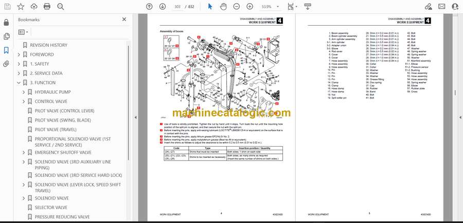
- Assembly of boom
- Boom assembly
- Assembly of boom swing
- Assembly of front light
- Assembly of blade
- Assembly of blade
- Disassembly and assembly
- Removal and installation of the bucket
- Release of residual pressure
- Removal and installation of the arm assembly
- Removal and installation of the boom assembly
- Removal and installation of the boom bracket
- Removal and installation of the blade
- Removal and installation of only each cylinder
- Removal and installation of the bucket cylinder
- Removal and installation of the arm cylinder
- Removal and installation of the boom cylinder
- Removal and installation of the swing cylinder
- Removal and installation of the blade cylinder
- Removal and installation of the angle blade cylinder
- HYDRAULIC OIL TANK
- Construction diagram
- Assembly of hydraulic oil tank
- Disassembly and assembly
- Removal and installation of the hydraulic oil tank
- Oil level inspection and replenishment of the hydraulic oil tank
- Method for bleeding air
- HYDRAULIC PUMP
- Construction diagram
- Disassembly
- Assembly
- Inspection and adjustments
- CONTROL VALVE
- Construction diagram
- Bucket section
- Boom section
- Left travel section
- P1/P2 inlet section
- Right travel section
- Swing section
- 1st service section
- Arm section
- Slew section
- Blade section
- 2nd service section
- 3rd service section
- Angle blade section
- Communication valve section
- Disassembly
- Removal of the relief valve assembly and anti-cavitation valve
- Disassembly of each section (bucket, left travel, right travel, swing, 1st service, arm, slew, blade, 2nd service, and angle blade)
- Disassembly of the boom section
- Disassembly of the P1/P2 inlet section
- Disassembly of the 3rd service section
- Disassembly of the communication valve section
- Removal of load check valve, poppets, etc.
- Disassembly of the valve housing
- Cleaning of each part
- Inspection of each part
- Assembly
- Assembly of valve housing
- Assembly of the section
- Assembly of each section (bucket, left travel, right travel, swing, 1st service, arm, slew, blade, 2nd service, and angle blade)
- Assembly of the boom section
- Assembly of P1/P2 inlet section
- Assembly of the 3rd service section
- Assembly of the communication valve section
- Assembly of the load check valves, poppets, etc.
- Installation of the relief valve assembly and anti-cavitation valve
- Relief valve maintenance procedure
- Anti-cavitation valve maintenance procedure
- Operation
- PILOT VALVE
- Construction
- Special tools
- Installation jig A
- Installation jig B
- Disassembly and Assembly
- Inspection and adjustment
- PILOT VALVE (SWING, BLADE)
- Construction diagram
- Special jig
- Disassembly and assembly
- Inspection and adjustment
- PILOT VALVE (TRAVEL)
- Construction diagram
- Disassembly and Assembly
- General precautions
- Special Jigs
- Disassembly
- Assembly
- Inspection and adjustment
- PROPORTIONAL SOLENOID VALVE (1ST/2ND SERVICE)
- Construction
- Disassembly and Assembly
- Inspection and adjustment
- EMERGENCY SHUTOFF VALVE
- SOLENOID VALVE (3RD AUXILIARY LINE PIPING)
- Construction
- Disassembly and Assembly
- Inspection and adjustment
- SOLENOID VALVE (3RD SERVICE HARD LOCK)
- Construction diagram
- Disassembly and assembly
- Disassembly of solenoid valve
- Assembly of solenoid valve
- SOLENOID VALVE (LEVER LOCK)
- Construction
- Disassembly
- Solenoid valve
- Relief valve
- Check valve
- Assembly
- Inspection and adjustment
- SOLENOID VALVE (ANGLE BLADE)
- Construction
- Disassembly and Assembly
- Inspection and adjustment
- SOLENOID VALVE (BLADE FLOAT)
- Construction
- Disassembly and Assembly
- Inspection and adjustment
- SELECTOR VALVE
- Construction
- Disassembly and Assembly
- Inspection and adjustment
- PRESSURE REDUCING VALVE
- Construction diagram
- Disassembly and assembly
- Inspection and adjustment
- CYLINDER
- Construction diagram
- Boom cylinder
- Arm cylinder
- Swing cylinder
- Disassembly and assembly
- Service standard
- Tools required for disassembly and assembly
- Disassembly
- Assembly
- CYLINDER
- Construction diagram
- Bucket cylinder
- Blade cylinder
- Blade cylinder
- Disassembly and assembly
- Disassembly
- Washing and storage
- Assembly
- Start-up operation
- ANGLE CYLINDER
- Construction
- Disassembly and Assembly
- Special tools
- Disassembly
- Assembly
- Inspection and adjustment
- Inspection after disassembly
- Inspection after assembly
- TRAVEL MOTOR
- Construction diagram
- Reduction gear
- Hydraulic motor
- Overview of maintenance
- Disassembly
- Precautions for disassembly
- Preparation
- Disassembly procedure
- Assembly
- Precautions for assembly
- Preparation
- Assembly procedure
- Service standard
- Seals
- Service standard for parts that wear out
- SLEW MOTOR
- Construction
- Hydraulic motor
- Reduction gears
- Brake valve
- Special tools
- Disassembly
- Slew motor
- Brake valve and hydraulic motor
- Reduction gears
- Anti-rebound valve
- Assembly
- Anti-rebound valve
- Brake valve and hydraulic motor
- Reduction gears
- Slew motor
- Inspection and adjustment
- SWIVEL JOINT
- Construction
- Disassembly and Assembly
- Inspection and adjustment
- Inspection procedures and remedial actions
- Use limit for parts
- Inspection after assembly
- MAIN UNIT HYDRAULIC PIPING & LOWER HYDRAULIC PIPING
- Main unit hydraulic piping
- Construction diagram
- Table of connections
- Lower hydraulic piping
- Construction diagram
- Table of connections
- 5. TROUBLESHOOTING
- TROUBLESHOOTING
- Notes on the malfunction diagnosis and repair
- GENERAL
- The engine does not start.
- 1. Did any error code occur?
- 2. Does the starter motor rotate?
- 3. Is there enough fuel?
- 4. Is the fuel filter clogged?
- The engine speed cannot be increased.
- 1. Did any error code occur?
- All the attachments and travel motors are inoperable.
- 1. Did any vehicle error code occur?
- 2. Is the hydraulic oil above the specified amount?
- 3. Is the pilot pressure within the standard value range?
- 4. Is the main pressure within the standard value range?
- All the attachments and travel motors are operable but are slow.
- 1. Does the engine speed reach the maximum?
- 2. Is the hydraulic oil above the specified amount?
- 3. Is abnormal sound coming from the hydraulic pump?
- 4. Is the pilot pressure within the standard value range?
- 5. Is the main pressure within the standard value range?
- TRAVEL
- The travel motors are inoperable (both left and right or one of them).
- 1. Do hydraulic devices other than the travel motor operate?
- 2. Is the discharge pressure from the pilot valve (for travel operation) normal?
- 3. Is the discharge pressure from the control valve (travel section) normal?
- 4. Is the discharge pressure from the swivel joint normal?
- The vehicle veers to one side with the left or right travel speed slowing down when it travels forward or backward.
- 1. Is the tension of the crawler normal?
- 2. Is any foreign matter trapped in the crawler?
- 3. Is the discharge pressure from the pilot valve (for travel operation) normal?
- 4. Is the discharge pressure from the control valve (travel section) normal?
- 5. Is the discharge pressure from the swivel joint normal?
- The travel speed cannot be changed.
- 1. Is the voltage applied to the solenoid valve (for variable travel speed)?
- 2. Is the variable travel speed pressure from the solenoid valve (for variable travel speed) normal?
- 3. Is the variable travel speed pressure (pilot pressure) from the swivel joint normal?
- SLEW
- The vehicle cannot slew.
- 1. Do hydraulic devices other than the slew operate?
- 2. Is the slew pressure within the standard value range?
- 3. Is the hydraulic piping that supplies the slew brake release pressure abnormal?
- 4. Does the slew bearing rotate?
- 5. Is the discharge pressure from the pilot valve (for slew operation) normal?
- 6. Is the discharge pressure from the control valve (slew section) normal?
- The vehicle cannot slew to the left or right.
- 1. Is the slew pressure within the standard value range?
- 2. Is the hydraulic piping that supplies the slew brake release pressure abnormal?
- 3. Is the discharge pressure from the pilot valve (for slew operation) normal?
- 4. Is the discharge pressure (main pressure) from the control valve (slew section) normal?
- 5. Is the slew relief valve normal?
- The vehicle can slew but is slow and less powerful.
- 1. Do hydraulic devices other than the slew operate normally?
- 2. Is the slew pressure below the standard value range?
- 3. Is the slew relief valve or relief valve seat abnormal?
- 4. Is the discharge pressure from the pilot valve (for slew operation) normal?
- 5. Is the discharge pressure from the control valve (slew section) normal?
- The slewing stop flow amount is large or the vehicle cannot stop.
- 1. Is the slew pressure below the standard value range?
- 2. Can the pilot valve (for slew operation) be in the neutral status?
- 3. Can the control valve (slew section) be in the neutral status?
- BOOM
- The boom cannot rise or drop.
- 1. Do hydraulic devices other than the boom operate?
- 2. Is the discharge pressure from the pilot valve (for boom operation) normal?
- 3. Is the discharge pressure from the control valve (boom section) normal?
- The boom can rise and drop but is slow and less powerful.
- 1. Do hydraulic devices other than the boom operate normally?
- 2. Is the discharge pressure from the pilot valve (for boom operation) normal?
- 3. Is the discharge pressure from the control valve (boom section) normal?
- 4. Is the boom cylinder internally leaking?
- The boom drops temporarily when the boom control lever is slowly pulled.
- 1. Is the boom cylinder internally leaking?
- The amount of boom natural drop is large.
- 1. Is the boom cylinder internally leaking?
- 2. Is the boom emergency shutoff valve internally leaking?
- ARM
- The arm cannot be pushed or pulled.
- 1. Do hydraulic devices other than the arm operate?
- 2. Is the discharge pressure from the pilot valve (for arm operation) normal?
- 3. Is the discharge pressure from the control valve (arm section) normal?
- The arm can be pushed and pulled but is slow and less powerful.
- 1. Do hydraulic devices other than the arm operate normally?
- 2. Is the discharge pressure from the pilot valve (for arm operation) normal?
- 3. Is the discharge pressure from the control valve (arm section) normal?
- The amount of arm natural drop is large.
- 1. Is the arm emergency shutoff valve internally leaking?
- BUCKET
- The bucket cannot dig or remove the ground.
- 1. Do hydraulic devices other than the bucket operate?
- 2. Is the discharge pressure from the pilot valve (for bucket operation) normal?
- 3. Is the discharge pressure from the control valve (bucket section) normal?
- The bucket can dig and remove the ground but is slow and less powerful.
- 1. Do hydraulic devices other than the bucket operate normally?
- 2. Is the discharge pressure from the pilot valve (for bucket operation) normal?
- 3. Is the discharge pressure from the control valve (bucket section) normal?
- The amount of bucket natural drop is large.
- 1. Is the hydraulic piping connected to the bucket cylinder failing, such as leaking?
- SWING
- The vehicle cannot swing.
- 1. Do hydraulic devices other than the swing operate?
- 2. Is the discharge pressure from the pilot valve (for swing operation) normal?
- 3. Is the discharge pressure from the control valve (swing section) normal?
- The vehicle can swing but is slow and less powerful.
- 1. Do hydraulic devices other than the swing operate normally?
- 2. Is the discharge pressure from the pilot valve (for bucket operation) normal?
- 3. Is the discharge pressure from the control valve (swing section) normal?
- The amount of swing natural drop is large.
- 1. Is the hydraulic piping connected to the swing cylinder failing, such as leaking?
- BLADE
- The blade does not rise or drop.
- 1. Do hydraulic devices other than the blade operate?
- 2. Is the linkage normal?
- 3. Is the discharge pressure from the control valve (blade section) normal?
- 4. Is the discharge pressure from the swivel joint normal?
- The blade can rise and drop but is slow and less powerful.
- 1. Do hydraulic devices other than the blade operate normally?
- 2. Is the linkage normal?
- 3. Is the discharge pressure (main pressure) from the control valve (blade section) normal?
- 4. Is the discharge pressure (main pressure) from the swivel joint normal?
- The amount of blade natural drop is large.
- 1. Is the hydraulic piping connected to the blade cylinder failing, such as leaking?
- SERVICE
- The attachment connected to the 1st service is inoperable.
- 1. Do hydraulic devices other than the 1st service operate?
- 2. Is the voltage applied to the proportional solenoid valve (for 1st service)?
- 3. Is the pressure on the 1st service A and B within the standard value range?
- 4. Is the discharge pressure from the proportional solenoid valve (for 1st service) normal?
- The attachment connected to the 2nd service is inoperable.
- 1. Do hydraulic devices other than the 2nd service operate?
- 2. Is the voltage applied to the solenoid valve (for 2nd service and 4th service switching)?
- 3. Is the voltage applied to the proportional solenoid valve (for 2nd service)?
- 4. Is the pressure on the 2nd service A and B within the standard value range?
- 5. Is the discharge pressure from the proportional solenoid valve (for 2nd service) normal?
- 6. Is the discharge pressure from the control valve (2nd service section) normal?
- The quick-hitch cannot be locked (3rd service).
- 1. Do hydraulic devices other than the quick-hitch operate?
- 2. Is the pressure on the 3rd service A normal?
- 3. Is the hydraulic piping connected to the 3rd service A failing?
- The quick-hitch cannot be unlocked (3rd service).
- 1. Do hydraulic devices other than the quick-hitch operate?
- 2. Is the pressure on the 3rd service B within the standard value range?
- 3. Is the voltage applied to the solenoid valve (for 3rd service)?
- 4. Is the discharge pressure from the solenoid valve (for 3rd service) normal?
- HYDRAULIC PUMP
- CONTROL VALVE
- 1. Control valve in general
- 2. Relief valve
- 3. Hydraulic control in general
- PILOT VALVE (OPERATION LEVER, SWING, BLADE)
- PILOT VALVE (TRAVEL)
- SOLENOID VALVE (3RD SERVICE)
- SOLENOID VALVE (LEVER LOCK)
- SOLENOID VALVE (ANGLE BLADE)
- REDUCING VALVE
- CYLINDER
- Troubleshooting problems with the cylinder
- TRAVEL MOTOR
- SLEW MOTOR
- Hydraulic motor, brake valve
- Parking brake
- 6. OTHER
- MAINTENANCE SOFTWARE MANUAL
- CONTENTS
- 1. OVERVIEW
- 2. CONNECTION METHOD
- 2-1. Parts needed
- 2-2. Installation method
- 2-2-1. Installation of “PLUS+1 Service Tool”
- 2-2-2. Installation of maintenance tool driver
- 2-3. Connection to work machine and startup of maintenance software
- 3. FUNCTION DESCRIPTION
- 3-1. Home
- 3-2. Machine status
- 3-2-1. Pin wiring of controller
- 3-2-2. Inputs
- 3-2-3. Outputs
- 3-2-4. Switch
- 3-2-5. Feedback
- 3-2-6. CAN
- 3-2-7. Error code
- 3-2-8. Vehicle status
- 3-3. Engine status
- 3-4. AUX
- 3-4-1. AUX1
- 3-4-1.1 Grip setting
- 3-4-1.2 Stroke setting
- 3-4-1.3 Current setting
- 3-4-1.4 Factory default
- 3-4-2. AUX2 AUX4
- 3-4-2.1 Grip setting
- 3-4-2.2 Stroke setting
- 3-4-2.3 Current setting
- 3-4-2.4 Factory default
- 3-5. Other
- 3-5-1. Hydraulic pump
- 3-5-2. Lift alarm
- 3-5-3. Misc
- 3-5-4. Engine auto stop
- 3-5-5. Operating lever switch
- 3-5-6. Immobilizer
- 3-5-7. Hour meter
- 3-5-8. Option
- AIR CONDITIONER
- Construction diagram
- Assembly of compressor
- Assembly of condenser
- Assembly of air conditioner unit
- Disassembly and assembly
- Removal and installation of the compressor
- Removal and installation of the condenser
- Removal and installation of the receiver dryer
- Removal and installation of the air conditioner unit
- LEVER SWITCH PATTERN SWITCHING METHOD
- Included parts
- Pattern switching method
- Standard lever switch pattern
- Case 1: When switching the 1st service and the 2nd service of the slide switch
- Case 2: When switching A and B or switching C and D
- Case 4: When assigning the detent function to the button B
- Special case 1: When switching the 1st service and the 2nd service
- Special case 2: When switching the 1st service and the 2nd service and also switching A and B or switching C and D
- TABLE OF VEHICLE ERROR CODES
- TROUBLESHOOTING BY VEHICLE ERROR CODE
- 9: Key ON detection not possible
- 402: CAN0 communication error
- 502: CAN communication error (ECU)
- 602: CAN communication error (cluster)
- 812: CAN communication error (switch assembly)
- 822: CAN communication error (immobilizer)
- 832: CAN communication error (dial)
- 842: CAN communication error (radio)
- 1703: Main controller power supply voltage error (high voltage)
- 1704: Main controller power supply voltage error (low voltage)
- 2503: Main controller sensor voltage error (high voltage)
- 2504: Main controller sensor voltage error (low voltage)
- 3300: Alternator charge fault
- 3360: DPF full (Lv2)
- 3370: DPF full (Lv1)
- 3380: DPF ash load
- 3401: Engine oil pressure error
- 3500: Overheating
- 3600: Air cleaner clogging
- 3700: Water separator error
- 3843: CCV heater 1 (IN) voltage error (high voltage)
- 3844: CCV heater 1 (IN) voltage error (low voltage)
- 5363: Air conditioner servo sensor voltage error (high voltage)
- 5364: Air conditioner servo sensor voltage error (low voltage)
- 5503: Fuel sender voltage error (high voltage)
- 5504: Fuel sender voltage error (low voltage)
- 5603: Lift alarm sensor voltage error (high voltage)
- 5603: Boom cylinder head side pressure sensor voltage error (high voltage)
- 5604: Lift alarm sensor voltage error (low voltage)
- 5604: Boom cylinder head side pressure sensor voltage error (low voltage)
- 5613: Boom angle sensor voltage error (high voltage)
- 5614: Boom angle sensor voltage error (low voltage)
- 5633: Arm angle sensor voltage error (high voltage)
- 5634: Arm angle sensor voltage error (low voltage)
- 5953: Boom cylinder rod side pressure sensor voltage error (high voltage)
- 5954: Boom cylinder rod side pressure sensor voltage error (low voltage)
- 6503: 1st service slide switch voltage error (high voltage)
- 6504: 1st service slide switch voltage error (low voltage)
- 6509: 1st service slide switch neutral position error
- 6519: 1st service (A) button error
- 6529: 1st service (B) button error
- 6603: 2nd service slide switch voltage error (high voltage)
- 6604: 2nd service slide switch voltage error (low voltage)
- 6609: 2nd service slide switch neutral position error
- 6709: 3rd service switch error (foot + grip)
- 6719: 3rd service switch error (foot)
- 8005: Pump PWM output current error (low current)
- 8015: 1st service (A) PWM output current error (low current)
- 8025: 1st service (B) PWM output current error (low current)
- 8035: 2nd service (C) PWM output current error (low current)
- 8045: 2nd service (D) PWM output current error (low current)
- 8774: Air conditioner servo motor 1 output current error
- 8784: Air conditioner servo motor 2 output current error
- 9900: Option setting change (TFM)
- 9990: Model change
- 9991: Unknown model
- TABLE OF ENGINE ERROR CODES
Takeuchi


