Takeuchi TL12R2 Track Loader Workshop Manual (CR1E022) (SN 412100002-)
On a TL12R2 that lives in mud, rock piles, and tight construction sites, this workshop manual is what I’d keep open when the machine is down and time is tight. It walks you through step‑by‑step repair sequences so you’re not guessing, especially on bigger jobs like pulling a drive motor after a track quits pulling or chasing a hydraulic leak under the cab. I use it to trace systems in a logical order, verify what to loosen first, and make sure everything goes back aligned and sealed so the loader can go straight back to grading or loading trucks.
Applications & Use Cases
- Isolate hydraulic faults and trace lines so you’re not tearing into the wrong circuit.
- Follow structured teardown and reassembly steps for major components like final drives and lift arms.
- Inspect wear points—pins, bushings, track components—with clear criteria before you order parts.
- Route hoses and harnesses correctly after repairs so nothing rubs, pinches, or overheats.
- Perform post-repair checks to test functions safely before releasing the machine back to work.
FAQ
Q: Can I keep this manual on a tablet in the field?
A: Yes, it’s practical to use on a tablet or laptop; zooming in on diagrams helps when you’re working in tight spots.
Q: Is it worth printing sections of this manual?
A: Printing the procedures you’re doing that day is handy—you can mark torque steps, oil smudges don’t matter, and you won’t risk a device around grease and weld spatter.
Safety Note
Always lock out the machine, support raised components securely, and verify zero pressure before opening any hydraulic or mechanical assembly.
Takeuchi TL12R2 Track Loader Index:
- REVISION HISTORY
- FOREWORD
- Directional terms: front, rear, left, right
- Machine serial number
- Symbols used in this manual
- Manual structure
- 1. SAFETY
- SAFETY ALERT SYMBOL
- SAFETY PRECAUTIONS
- Observe all safety rules
- Wear safe clothing and protective gear
- Install an extinguisher and a first aid kit
- Lockout/Tagout (LOTO)
- Use the correct tools
- Regularly replace the safety-critical parts
- Explosionproof lighting
- Prohibit access by unauthorized persons
- Prepare the work area
- When the canopy is tilted up
- Keep the machine clean
- Stop the engine before performing maintenance
- Keep clear of the moving fan and belt
- When working under the machine
- When working on the machine
- Securing the working equipment
- Secure the engine hood and guard when they are open
- Place heavy components in a stable position
- Caution when filling with fuel or oil
- Handling of hoses
- Be careful with hot and pressurized components
- Handling of radiator
- Be careful with oils under pressure
- Release the residual pressure from the hydraulic system before performing maintenance
- Be careful with grease under pressure
- Handling of the accumulator
- Disconnect the battery
- Use caution when handling batteries
- Have a service agent repair welding cracks or other damage
- Checks after maintenance
- Disposing of wastes
- Cautions for handling DEF/AdBlue®
- CAUTIONS WHEN WORKING
- Before starting work
- When disassembling or assembling
- When removing/installing the hydraulic unit
- When connecting/disconnecting the hoses or pipes
- Handling of seals
- Pressure adjustment for hydraulic devices
- 2. SERVICE DATA
- DIMENSIONAL DRAWING
- Machine dimensions
- Operating range
- SPECIFICATION TABLES
- Performance
- Dimensions
- Mass
- Engine
- Hydraulic system
- Brake device
- Undercarriage
- Operating device
- Working equipment
- Hydraulic system
- TABLE OF MASSES
- Upper structure
- Lower structure
- Attachments
- LUBRICANT AND FUEL CHART
- Diesel fuel standards
- Handling DEF/AdBlue®
- PERFORMANCE CRITERIA
- Standard values table
- Hydraulic pump assignment table
- Machine without high-flow equipment
- Machine with high-flow equipment
- Methods for inspecting performance
- 1. Engine speed
- 2. Hydraulic oil pressure
- 3. Cylinder speed
- 4. Travel speed
- 5. Crawler shoe 5 rotations
- 6. Straight-ahead traveling
- 7. Hydraulic cylinder natural drop
- 8. Natural travel drop
- 9. Crawler tension
- 10. Bucket front edge
- TIGHTENING TORQUE
- Hydraulic hose
- Bite-type pipe fitting for steel pipe
- Joint for piping
- Joint for piping (O-ring seal type)
- Bolts and nuts (JIS strength category 10.9)
- HYDRAULIC CIRCUIT DIAGRAM
- Standard flow specification
- Serial No.: 412100002 to 412100701
- Serial No.: 412100702 or later / 412300001 or later
- High flow and pattern change specification
- Serial No.: 412100002 to 412100701
- Serial No.: 412100702 or later / 412300001 or later
- High flow specification
- ELECTRICAL CIRCUIT DIAGRAM
- Symbols in electrical circuit diagram
- Wire color symbols
- Wire color table
- Wire types
- Schematic diagram
- Serial No.: 412100002 to 412100368
- Serial No.: 412100369 to 412101079
- Serial No.: 412101080 to 412101661
- Serial No.: 412101662 to 412101967
- Serial No.: 412101968 to 412103515
- Serial No.: 412103516 or later
- Serial No.: 412300001 to 412300005
- Serial No.: 412300006 or later
- HYDRAULIC DEVICE LAYOUT DIAGRAM
- 3. FUNCTION
- HST PUMP
- Hydraulic pump
- Control section
- Charge check/high-pressure relief valve assembly
- Charge check valve
- High-pressure relief valve
- Charge relief valve
- GEAR PUMP
- CONTROL VALVE
- At the neutral position
- AUX1 operation
- Arm-raising operation
- Arm-lowering operation
- Bucket roll-back operation
- Bucket dump operation
- Flow rate adjustment valve
- When arm float is turned off
- Arm float operation
- Main relief valve
- Overload relief valve
- SUB VALVE
- When the solenoid valve A is not energized:
- When the solenoid valve A is energized:
- When the solenoid valve B is not energized:
- When the solenoid valve B is energized:
- PILOT VALVE
- When the lever (1) is in the neutral position:
- When the lever (1) is tilted:
- When the lever (1) is kept at a certain position:
- PROPORTIONAL CONTROL SOLENOID VALVE (ACTIVE POWER CONTROL)
- PROPORTIONAL SOLENOID VALVE (1ST SERVICE)
- SOLENOID VALVE (PARKING BRAKE)
- CYLINDER
- TRAVEL MOTOR
- 4. DISASSEMBLY AND ASSEMBLY
- SERVICE STANDARDS
- Track roller A
- Track roller B
- Sprocket
- Idler
- Clearance for pin and bushing
- Replacing the pin and bushing
- DRIVE SYSTEM
- Engine
- Radiator
- Construction diagram
- Removing the engine
- Installing the engine
- Hydraulic pump (without high-flow equipment)
- Hydraulic pump (with high-flow equipment)
- Construction diagram
- Removing the hydraulic pump
- Installing the hydraulic pump
- Bleeding air from the HST pump
- Fuel tank
- Construction diagram
- Removing the fuel tank
- Installing the fuel tank
- TRAVEL SYSTEM
- Track roller (Serial No.: 412100002 to 412100418)
- Track roller (Serial No.: 412100419 to 412100611)
- Track roller (Serial No.: From 412100612)
- Front idler (Serial No.: 412100002 to 412100574)
- Front idler (Serial No.: From 412100575)
- Grease cylinder
- Travel motor
- Construction diagram
- Removing the crawler
- Installing the crawler
- Removing the track roller A and C
- Installing the track roller A and C
- Removing the track roller B
- Installing the track roller B
- Removing the front idler and grease cylinder
- Installing the front idler and grease cylinder
- Removing the travel motor
- Installing the travel motor
- FRAME
- Machine frame
- Tilting up the canopy and cab
- How to raise (tilt up) the canopy and cab
- How to lower the canopy/cab
- Lift arm stopper
- How to install the stopper
- How to remove the stopper
- Floor frame
- Construction diagram
- Removing the floor frame
- Installing the floor frame
- Cover assembly (canopy)
- Construction diagram
- Removing the covers
- Installing the covers
- Cover assembly (cab)
- Construction diagram
- Removing the covers
- Installing the covers
- Center cover assembly
- Rear door assembly
- Engine hood assembly
- Canopy mounting assembly
- Canopy exterior assembly
- Canopy interior assembly
- Cab mounting assembly
- Cab exterior assembly
- Front door assembly
- Side window assembly
- Cab interior assembly
- Construction diagram
- Removing the canopy assemble/cab assemble
- Installing the canopy/cab
- OPERATING DEVICE
- Remote control piping assembly
- Construction diagram (machine without selector valve)
- Construction diagram (machine with selector valve)
- Disassembly and assembly
- Removal and installation of the accumulator
- ATTACHMENTS
- Mechanical quick-hitch assembly
- Hydraulic quick-hitch assembly
- Construction diagram
- Switch (36) adjustment method
- Removing the quick-hitch
- Installing the quick-hitch
- Lift arm
- Construction diagram
- Removing the lift arm
- Installing the lift arm
- Attachment pipe assembly (machine without high-flow equipment, machine with mechanical quick-hitch, machine with 1st service 1/2 quick coupler, machine without 2nd service, machine without ride control)
- Attachment pipe assembly (machine without high-flow equipment, machine with mechanical quick-hitch, machine with 1st service 1/2 quick coupler, machine without 2nd service, machine with ride control)
- Attachment pipe assembly (machine with hydraulic quick-hitch, machine with 1st service 1/2 quick coupler, machine without 2nd service, machine without ride control)
- Attachment pipe assembly (machine with hydraulic quick-hitch, machine with 1st service 1/2 quick coupler, machine without 2nd service, machine with ride control)
- Attachment pipe assembly (machine with hydraulic quick-hitch, machine with 1st service 1/2 and 3/4 quick coupler, machine with 2nd service, machine with ride control)
- Attachment pipe assembly (machine with hydraulic quick-hitch, machine with 1st service 1/2 and 3/4 quick coupler, machine with 2nd service, machine with ride control)
- Block coupler (machine with 1st service 1/2 quick coupler)
- Block coupler (machine with 1st service 1/2 and 3/4 quick coupler, machine with 2nd service)
- HYDRAULIC TANK
- Construction diagram
- Removing the hydraulic tank
- Installing the hydraulic tank
- Filling with hydraulic oil
- Bleeding the air
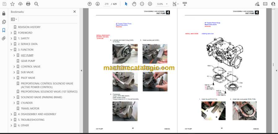
- HST PUMP
- GEAR PUMP
- Construction
- Exploded diagram
- Internal construction diagram
- Disassembly and assembly
- General precautions
- Disassembly
- Assembly
- GEAR PUMP (HIGH FLOW)
- Construction
- Exploded diagram
- Internal construction diagram
- Disassembly and assembly
- General precautions
- Disassembly
- Assembly
- CONTROL VALVE
- Construction
- Disassembly
- General precautions
- Removing the spool
- Removing the check valve and load check valve
- Removing the main relief valve
- Removing the overload relief valve
- Removing the flow ratio adjuster valve
- Removing the arm float valve and leveling cancel valve
- Removing the solenoid valve
- Removing other parts
- Assembly
- Main unit
- Spool assembly
- Check valve, load check valve
- Installing the overload relief valve
- Installing the arm float valve and leveling cancel valve
- Installing the solenoid valve
- Installing other parts
- Adjustment
- Adjusting the flow ratio
- Flow rate adjustment
- SUB VALVE
- Construction
- Disassembly and assembly
- General precautions
- Disassembly
- Inspection and adjustment
- PILOT VALVE
- Construction
- Special tools
- Installation jig A
- Installation jig B
- Disassembly and assembly
- General precautions
- Disassembly
- Assembly
- Inspection and adjustment
- SOLENOID VALVE (PARKING BRAKE)
- Construction
- Disassembly and Assembly
- Inspection and adjustment
- PROPORTIONAL CONTROL SOLENOID VALVE
- Construction
- Disassembly and Assembly
- Inspection and adjustment
- PROPORTIONAL CONTROL SOLENOID VALVE (1ST AUXILIARY LINE PIPING)
- Construction
- Solenoid proportional pressure reducing valve
- Disassembly and assembly
- General precautions
- Disassembly
- Assembly
- Service standards
- CYLINDER
- Lift arm cylinder
- Bucket cylinder (left)
- Bucket cylinder (right)
- Disassembly and assembly
- Service standards
- Inspection after assembly
- Tools required
- Special jigs
- Disassembly
- Assembly
- TRAVEL MOTOR
- WIRE HARNESS
- Electrical wiring assembly: 06942-00271-01
- Wire harness: 06842-00174-00
- Wire harness: 06942-00067-03
- Wire harness: 06942-00069-04
- Wire harness: 06942-00071-04
- Wire harness: 06942-00173-03
- Wire harness: 06942-00179-00
- Wire harness: 06942-00199-02
- Wire harness: 06942-00201-02
- Wire harness: 06942-00202-00
- Unit assembly 06942-00291-00
- Wire harness: 06942-00186-04
- Wire harness: 06942-00218-01
- GPS Unit Assembly
- Cabin specification 06942-00159-00
- Canopy specification 06942-00176-00
- Wire harness: 06942-00172-00
- Battery assembly: 06944-00006-02
- Radio assembly: 06947-00004-03
- Wire harness: 06847-00004-00
- Attachment wiring assembly (machine with mechanical quick-hitch): 06942-00273-00
- Wire harness: 06942-00277-01
- Attachment wiring assembly (machine with hydraulic quick-hitch): 06942-00281-00
- Wire harness: 06942-00285-01
- Cabin wiring diagram
- Wire harness: 06986-00229-00
- 5. TROUBLESHOOTING
- ABOUT THE TROUBLESHOOTING SECTION
- Notes on troubleshooting and servicing
- OVERALL MACHINE
- No operation is possible.
- All systems working, but insufficient power.
- Lift arm and bucket fail to move or are too slow.
- TRAVELING
- Traveling fails.
- Right or left travel speed decelerates and the machine veers to one side.
- Operating temperature of the travel system is too high.
- 2nd-speed travel is not possible.
- LIFT ARM
- Arm cylinder does not move
- Arm cylinder moves too slowly or lacks force
- When the control lever is pulled slowly, the lift arm drops once.
- Spontaneous drop of the lift arm is too large.
- BUCKET
- Bucket cylinder does not move.
- Bucket cylinder is slow or lacks force.
- Spontaneous drop of the bucket is too large
- SERVICE
- The prescribed pressure is not supplied to the 1st service
- GEAR PUMP
- SUB VALVE
- PILOT VALVE
- PROPORTIONAL SOLENOID VALVE (ACTIVE POWER CONTROL, 1ST AUXILIARY LINE PIPING)
- CYLINDER
- 6. OTHER
- MAINTENANCE SOFTWARE MANUAL
- CONTENTS
- 1. OUTLINE
- 2. CONNECTION METHODS
- 2-1. Items needed
- 2-2. Installation of the PLUS+1 GUIDE Service Tool
- 2-3. Installation of the Maintenance Tool driver
- 2-4. Connection to the machine and startup of the Maintenance Software
- 3. DESCRIPTION OF FUNCTIONS
- 3-1. Home
- 3-2. Machine status
- Inputs1
- Inputs2
- Outputs
- CAN
- Feedback
- Error code
- Vehicle status
- 3-3. Engine status
- Engine status
- DPF status
- SCR status
- 3-4. AUX1 Setting
- AUX1
- Grip setting
- Stroke setting
- 1way current setting
- 2way current setting
- HF current setting
- 3-5. Active power control
- Active power control (without selector valve)
- Active power control (with selector valve)
- Active power control
- 3-6. Other
- Option
- Hourmeter
- Misc
- Display
- Immobilizer
- AIR CONDITIONER
- Compressor assembly
- Condenser assembly
- Air conditioner unit
- AC component
- AIR CONDITIONER SYSTEM
- Overview of System Operation
- Truck and Heavy Equipment Systems
- Air Conditioner—System Operation
- Heater System Operation
- Environmental Effects on System Operation
- Chapter Review
- Inspection and Maintenance without gauges
- Discussion of Inspection & Maintenance Survey Results
- Visual Inspection – System Off
- Electrical System Inspection
- Performance Inspection – Engine Running
- Heater System Inspection
- Preventive Maintenance Worksheet
- Chapter Review
- Troubleshooting & Service Procedures
- Troubleshooting Overview
- The Key–Understanding System Function
- A Troubleshooting Example
- Manifold Gauge Set Installation
- Troubleshooting by Manifold Gauge Set Readings
- Review of Frequent Problem Areas
- Conclusion
- TABLE OF VEHICLE ERROR CODES
- ENGINE ERROR CODES
Takeuchi


