Takeuchi TL6R Track Loader Workshop Manual (CR2E015) (SN 406000005-)
Out on construction sites or in tight landscaping work, the TL6R is usually pushing, grading and loading all day in dust, mud and vibration. This workshop manual is what I reach for when I need a clear, step‑by‑step path to strip, repair and correctly reinstall major components so the loader goes back to work without comebacks. If, for example, the machine comes in with weak travel on one side, I use this book to trace the issue from basic checks through deeper inspection of the drive components and verify everything is set back to spec before it leaves the shop.
Applications & Use Cases
- Plan a full teardown and rebuild of major assemblies with a logical sequence so you don’t miss fasteners, shims or seals.
- Inspect and verify wear limits on key parts before you decide to reuse or replace them.
- Isolate hydraulic or drive complaints by following the recommended diagnostic flow instead of guessing.
- Align and route hoses, harnesses and linkages correctly during reinstallation to avoid rub-throughs and repeat failures.
- Perform safe post-repair checks so the loader tracks straight, lifts properly and holds loads without drift.
FAQ
Q: Can I use this manual on a tablet in the field?
A: Yes, it works well digitally; you can zoom diagrams and use search to jump to the system you’re working on.
Q: Is it worth printing sections of this manual?
A: I often print the procedures I’m doing that day, mark them up with notes, and keep them with the job card for quick reference.
Safety Note
Always lock out, support, and relieve stored energy before you get under or between any part of this loader.
Takeuchi TL6R Track Loader Index:
- REVISION HISTORY
- FOREWORD
- Directional terms: front, rear, left, right
- Machine serial number
- Symbols used in this manual
- Manual structure
- 1. SAFETY
- SAFETY ALERT SYMBOL
- SAFETY PRECAUTIONS
- Observe all safety rules
- Wear safe clothing and protective gear
- Install an extinguisher and a first aid kit
- Lockout/Tagout (LOTO)
- Use the correct tools
- Regularly replace the safety-critical parts
- Explosionproof lighting
- Prohibit access by unauthorized persons
- Prepare the work area
- When the canopy is tilted up
- Keep the machine clean
- Stop the engine before performing maintenance
- Keep clear of the moving fan and belt
- When working under the machine
- When working on the machine
- Securing the working equipment
- Secure the engine hood and guard when they are open
- Place heavy components in a stable position
- Caution when filling with fuel or oil
- Handling of hoses
- Be careful with hot and pressurized components
- Handling of radiator
- Be careful with oils under pressure
- Release the residual pressure from the hydraulic system before performing maintenance
- Be careful with grease under pressure
- Disconnect the battery
- Use caution when handling batteries
- Have a service agent repair welding cracks or other damage
- Checks after maintenance
- Disposing of wastes
- CAUTIONS WHEN WORKING
- Before starting work
- When disassembling or assembling
- When removing/installing the hydraulic unit
- When connecting/disconnecting the hoses or pipes
- Handling of seals
- Pressure adjustment for hydraulic devices
- 2. SERVICE DATA
- Dimensional drawing
- Machine dimensions
- Operating range
- SPECIFICATION TABLES
- Performance
- Dimensions
- Mass
- Engine
- Hydraulic system
- Brake device
- Undercarriage
- Operating device
- Working equipment
- Hydraulic system
- Table of masses
- Upper structure
- Lower structure
- Attachments
- Lubricant and fuel chart
- PERFORMANCE CRITERIA
- Standard values table
- Hydraulic pump assignment table
- Methods for inspecting performance
- 1. Engine speed
- 2. Hydraulic oil pressure
- 3. Cylinder speed
- 4. Travel speed
- 5. Crawler shoe 5 rotations
- 6. Straight-ahead traveling
- 7. Hydraulic cylinder natural drop
- 8. Natural travel drop
- 9. Crawler tension
- 10. Bucket front edge
- TIGHTENING TORQUE
- Hydraulic hose
- Bite-type pipe fitting for steel pipe
- Joint for piping
- Joint for piping (O-ring seal type)
- Bolts and nuts (JIS strength category 10.9)
- HYDRAULIC CIRCUIT DIAGRAM
- ELECTRICAL CIRCUIT DIAGRAM
- Symbols in electrical circuit diagram
- Wire color symbols
- Wire color table
- Wire types
- Schematic diagram
- Serial No.: 406000005 to 406001941
- Serial No.: 406001942 to 406002286
- Serial No.: 406002287 to 406002516 (excluding 406002469, 406002470, and 406002493)
- Serial No.: 406002469, 406002470, and 406002493
- Serial No.: 406002517 or later
- Serial No.: 406100001 to 406100017
- Serial No.: 406100018 to 406100028
- Serial No.: 406100029 or later
- HYDRAULIC DEVICE LAYOUT DIAGRAM
- 3. FUNCTION
- HST PUMP
- GEAR PUMP
- CONTROL VALVE
- Operation when arm-raising operation is activated:
- Operation when arm-lowering operation is activated:
- Operation when the bucket-tilt-backward operation is activated:
- Operation when the arm-float is turned off:
- Operation when the arm-float is activated:
- Load check valve
- Main relief valve
- The relief valve remains turned off:
- The relief valve is activated:
- Port relief valve
- Relief operation:
- Valve suction operation:
- Sub valve
- When the solenoid valve A is not energized:
- When the solenoid valve A is energized:
- When the solenoid valve B is not energized:
- When the solenoid valve B is energized:
- PILOT VALVE
- When the lever (1) is in the neutral position:
- When the lever (1) is tilted:
- When the lever (1) is kept at a certain position:
- Proportional control solenoid valve (active power control)
- PROPORTIONAL SOLENOID VALVE (1ST SERVICE)
- EMERGENCY VALVE
- RELIEF VALVE
- Cylinder
- TRAVEL MOTOR
- 4. DISASSEMBLY AND ASSEMBLY
- Service standards
- Track roller
- Sprocket
- Idler
- Clearance for pin and bushing
- Replacing the pin and bushing
- DRIVE SYSTEM
- Engine
- Radiator
- Construction diagram
- Removing the engine
- Installing the engine
- When starting the engine for the first time after installing it
- Removing the radiator
- Installing the radiator
- Hydraulic pump
- Construction diagram
- Removing the hydraulic pump
- Installing the hydraulic pump
- Bleeding air from the HST pump
- Fuel tank
- Construction diagram
- Removing the fuel tank
- Installing the fuel tank
- Travel system
- Track roller
- Front idler
- Grease cylinder
- Travel motor
- Construction diagram
- Removing the crawler
- Installing the crawler
- Removing the track roller A and C
- Installing the track roller A and C
- Removing the track roller B
- Installing the track roller B
- Removing the front idler and grease cylinder
- Installing the front idler and grease cylinder
- Removing the travel motor
- Installing the travel motor
- Frame
- Machine frame
- Tilting up the canopy and cab
- How to raise (tilt up) the canopy and cab
- How to lower (tilt down) the canopy and cab
- Lift arm stopper
- How to install the stopper
- How to remove the stopper
- Floor frame
- Construction diagram
- Removing the floor
- Installing the floor
- Cover assembly (Canopy specification machine) (Page 1 of 3)
- Cover assembly (Canopy specification machine) (Page 2 of 3)
- Cover assembly (Canopy specification machine) (Page 3 of 3)
- Cover assembly (Cabin specification machine) (Page 1 of 3)
- Cover assembly (Cabin specification machine) (Page 2 of 3)
- Cover assembly (Cabin specification machine) (Page 3 of 3)
- Construction diagram
- Removing the side cover assembly (left)
- Installing the side cover assembly (left)
- Removing the side cover assembly (right)
- Installing the side cover assembly (right)
- Removing the engine hood
- Installing the engine hood
- Removing the rear door assembly
- Canopy mounting assembly
- Canopy exterior assembly
- Canopy interior assembly
- Cab mounting assembly
- Cab exterior assembly
- Front door assembly
- Cab interior assembly
- Construction diagram
- Removing the canopy and cab
- Installing the canopy and cab
- Operating device
- Remote control piping assembly
- Remote control unit assembly
- Construction diagram
- Removing remote control unit
- Installing remote control unit
- Working device
- Mechanical quick-hitch assembly
- Hydraulic quick-hitch assembly
- Construction diagram
- Adjusting the switch (35) (1st service pipe connection switch)
- Removing the quick-hitch and bucket cylinder
- Installing the quick-hitch and bucket cylinder
- Adjusting the bucket stopper
- Lift arm assembly
- Construction diagram (Page 1 of 3)
- Construction diagram (Page 2 of 3)
- Construction diagram (Page 3 of 3)
- Removing the lift arm
- Installing the lift arm
- Arm stopper assembly
- Working device pipe assembly
- Hydraulic tank
- Hydraulic tank assembly
- Construction diagram
- Removing the hydraulic tank
- Installing the hydraulic tank
- Replenishing the hydraulic oil
- Bleeding the air
- HST PUMP
- GEAR PUMP
- Construction
- Disassembly
- Inspection and adjustment
- Checking the parts
- Test operation
- Measuring the discharge volume
- CONTROL VALVE
- Construction
- Disassembly and assembly
- General precautions
- Disassembly
- Inspection and adjustment
- Adjusting the flow ratio
- Adjustment procedure
- SUB VALVE
- Construction
- Disassembly and assembly
- General precautions
- Disassembly
- Inspection and adjustment
- PILOT VALVE
- Construction
- Special tools
- Installation jig A
- Installation jig B
- Disassembly and assembly
- General precautions
- Disassembly
- Assembly
- Inspection and adjustment
- PROPORTIONAL CONTROL SOLENOID VALVE
- Construction
- Disassembly and Assembly
- Inspection and adjustment
- Proportional solenoid valve (1st service)
- Construction diagram
- Disassembly and assembly
- Service standards
- EMERGENCY VALVE
- Three-view diagram
- Disassembly and assembly
- Disassembling the emergency valve
- Assembling the emergency valve
- TRAVEL MOTOR
- Wire harness
- Electrical wiring assembly: 06542-00021-01 (Page 1 of 2)
- Harness: 03343-40191-00
- Wire harness: 06643-00011-00
- Wire harness: 05642-00004-03
- Wire harness: 06542-00052-02
- Wire harness: 06542-00043-01
- Wire harness: 06542-00051-03
- Electrical wiring assembly: 06542-00021-01 (Page 2 of 2)
- Wire harness: 06542-00077-01
- Wire harness: 06542-00001-06
- Attachment wiring assembly: 06542-00022-02
- Wire harness: 06542-00044-00
- Wire harness: 06542-00113-02
- GPS device assembly: 06542-00114-00
- Cluster gauge assembly: 06542-00120-02
- Battery assembly: 06544-00004-02
- Radio assembly: 06547-00001-03
- Reversing camera assembly: 06542-00042-02
- Wire harness: 05642-00221-02
- Cable: 06542-00111-01
- Foot accelerator pedal assembly: 06541-00001-02
- Wire harness: 06542-00002-00
- Canopy wiring assembly
- Cabin wiring assembly
- Wire harness: 06542-00050-06
- Wire harness: 06584-00045-00
- Front door wiring assembly
- Wire harness: 06586-00090-00
- Switch assembly: 06586-00062-00 (Canopy specification machine)
- Switch assembly: 06586-00030-00 (Cabin specification machine)
- Engine wiring assembly (Page 1 of 2)
- Wire harness: 06542-00087-00
- Engine wiring assembly (Page 2 of 2)
- Wire harness: 19039-00255-00
- Quick-hitch wiring assembly
- Wire harness: 06542-00053-01
- 5. TROUBLESHOOTING
- Overall Machine
- Engine does not start
- Engine cannot speed up
- No operation is possible (travel, lift arm, bucket, services)
- All systems working (travel, lift arm, bucket, services) but insufficient speed and power
- Lift arm, bucket, and services all do not operate or the operation speed is slow (travel operates normally)
- Traveling
- Right and left travel motors do not operate
- Right or left travel speed decelerates and the machine veers to one side
- No variable travel speed
- Lift Arm
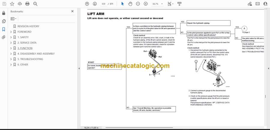
- Lift arm does not operate, or either cannot ascend or descend
- Lift arm can ascend or descend but the speed and force are low
- When the control lever is pulled slowly, the lift arm drops temporarily
- Spontaneous drop of the lift arm is too large
- Bucket
- Bucket does not operate, or cannot tilt either forward or backward
- Bucket can tilt backward or forward but the speed and force are low
- Spontaneous drop of the bucket is too large
- Services
- Service does not operate, or either Service A or B does not operate
- GEAR PUMP
- Control valve
- Sub Valve
- PILOT VALVE
- PROPORTIONAL SOLENOID VALVE (ACTIVE POWER CONTROL, 1ST AUXILIARY LINE PIPING)
- CYLINDER
- 6. OTHER
- MAINTENANCE SOFTWARE MANUAL
- CONTENTS
- 1. OUTLINE
- 2. CONNECTION METHODS
- 2-1. Items needed
- 2-2. Installation method
- 2-2-1. Installation of the PLUS+1 Service Tool
- 2-2-2. Installation of the maintenance tool driver
- 2-3. Connection to the machine and startup of the maintenance software
- 3. DESCRIPTION OF FUNCTIONS
- 3-1. Home (Main screen)
- 3-2. Machine status
- Inputs1
- Inputs2
- Outputs
- CAN
- Feedback
- Error code
- Vehicle status
- 3-3. Engine status
- Engine status
- DPF status
- DPF history
- 3-4. AUX1
- AUX1
- Grip setting
- Stroke setting
- Current setting
- 3-5. Active power control
- Active power control
- Scope
- 3-6. Other
- Air conditioner
- Compressor assembly
- Condenser assembly
- Air conditioner unit
- AC component
- AIR CONDITIONER SYSTEM
- Overview of System Operation
- Truck and Heavy Equipment Systems
- Air Conditioner—System Operation
- Heater System Operation
- Environmental Effects on System Operation
- Chapter Review
- Inspection and Maintenance without gauges
- Discussion of Inspection & Maintenance Survey Results
- Visual Inspection – System Off
- Electrical System Inspection
- Performance Inspection – Engine Running
- Heater System Inspection
- Preventive Maintenance Worksheet
- Chapter Review
- Troubleshooting & Service Procedures
- Troubleshooting Overview
- The Key–Understanding System Function
- A Troubleshooting Example
- Manifold Gauge Set Installation
- Troubleshooting by Manifold Gauge Set Readings
- Review of Frequent Problem Areas
- Conclusion
- Electrical wiring diagram
- Vehicle error codes
- Engine error codes
Takeuchi


