Format: PDF (Printable Document)
File Language: English
File Pages: 256
File Size: 13.84 MB (Speed Download Link)
Brand: Wacker Neuson
Model: 1404 ET16 Tracked Excavator
Type of Document: Service Manual
$ 45
1 Operation
1.1 Notices on this service manual
1.2 Identification of warnings and dangers
1.3 Explanation of symbols and abbreviations
1.4 Warranty and liability
1.5 Labels
1.6 Machine overview
1.7 Cabin overview
1.8 Cabin overview (legend)
1.9 Instrument panel overview
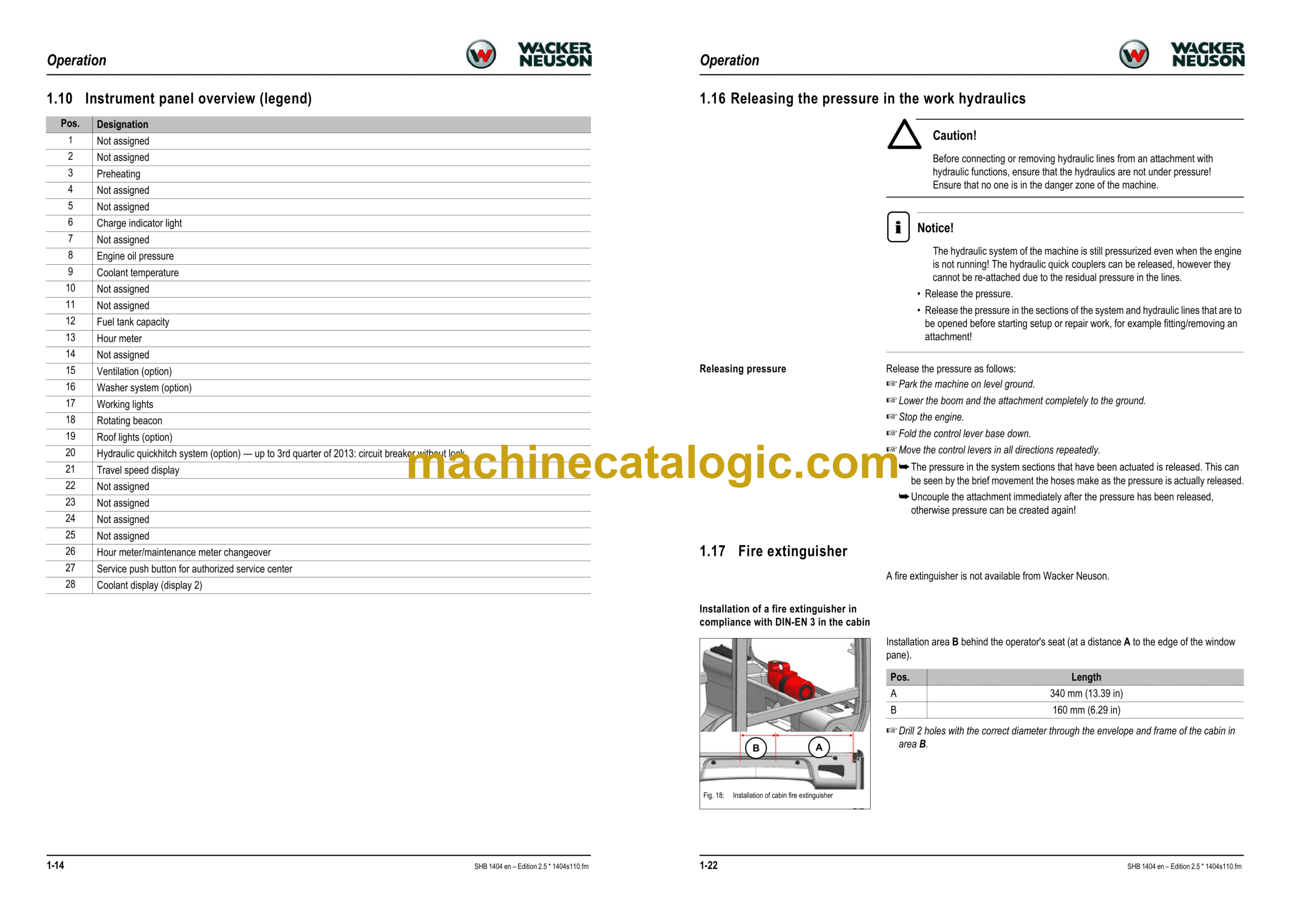
1.10 Instrument panel overview (legend)
1.11 Engine compartment (overview)
1.12 Chassis overview
1.13 Removing the cabin
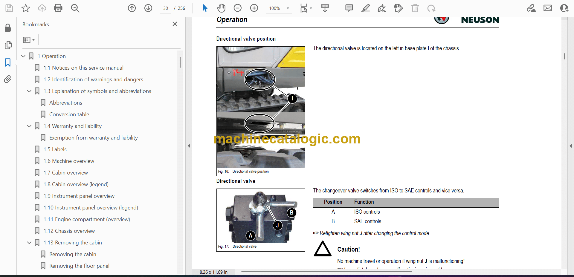
1.14 Changeover valve for SAE/ISO controls (option)
1.15 Functional check of control lever base
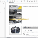
1.16 Releasing the pressure in the work hydraulics
1.17 Fire extinguisher
2 Technical data
2.1 Chassis
2.2 Engine
2.3 Hydraulic system
2.4 Travel gear and swivel unit
2.5 Stabilizer blade
2.6 Electrical system
2.7 Noise levels
2.8 Vibration
2.9 Coolant compound table
2.10 Hose identification code
2.11 Model-specific tightening torques
2.12 General tightening torques
2.13 Dimensions
2.14 Lift capacity table
2.15 Kinematics
2.16 Measuring live ring tolerance
3 Maintenance
3.1 Special tools
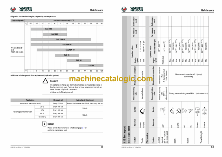
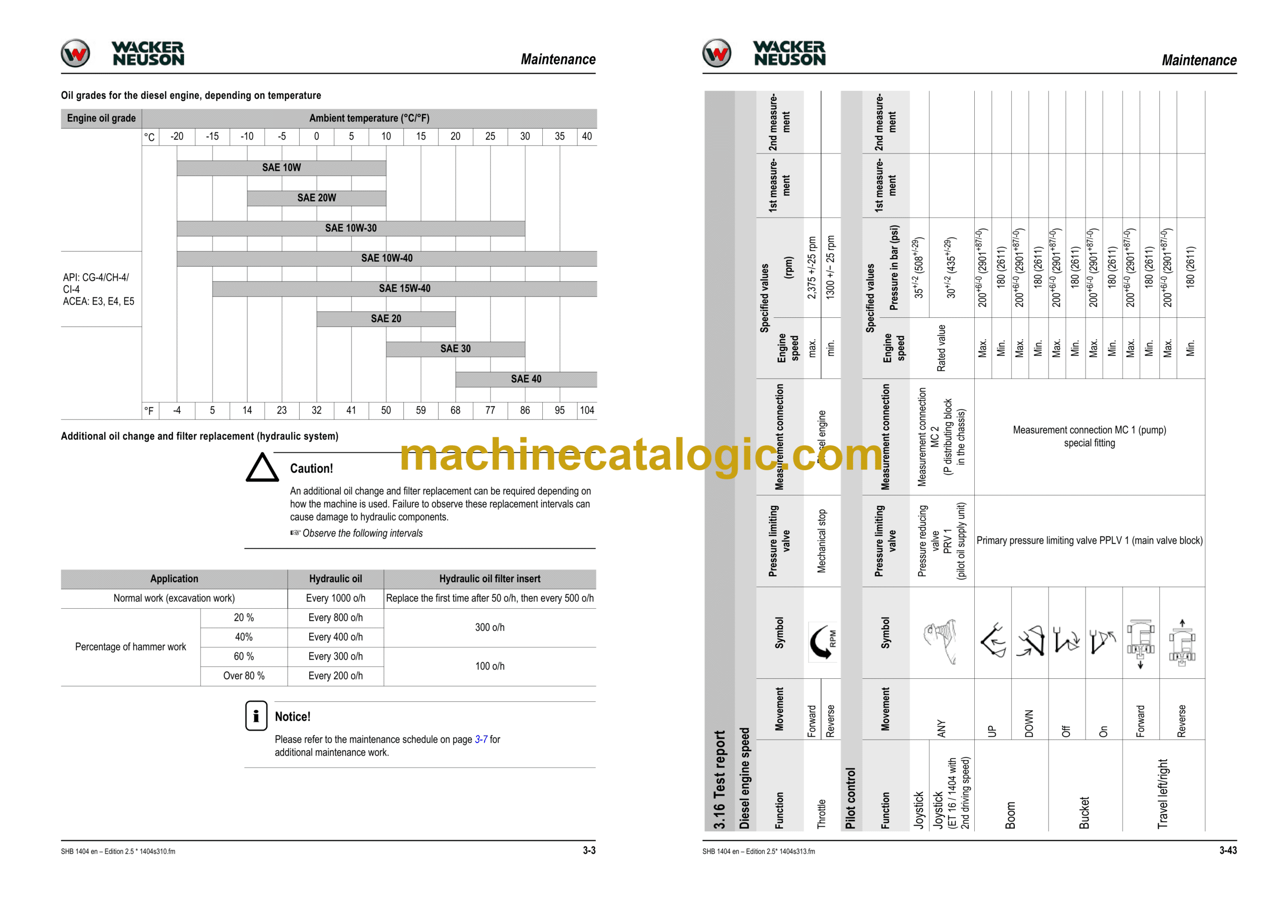
3.2 Fluids and lubricants
3.3 Maintenance label
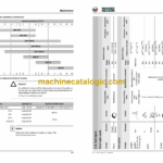
3.4 Maintenance plan (overview)
3.5 Information on maintenance
3.6 Fuel System
3.7 Engine lubrication system
3.8 Engine cooling system
3.9 Air filter (up to serial no. AG03215)
3.10 Air filter (from serial no. AG03216)
3.11 Replacing the cabin air filter
3.12 V-belt
3.13 Hydraulic system
3.14 Pilot control filter (from serial no. AF01441)
3.15 Pressure check
3.16 Test report
3.17 Traveling drive
3.18 Tracks
3.19 Lubrication points
3.20 Overview of lubrication points
3.21 Lubrication work
3.22 Electrical system
3.23 General maintenance
3.24 Preparatory work before taking out of service
3.25 Maintenance when out of service for a longer period of time
4 Engine
4.1 Overview of engine 3TNV76-SNS2 (Tier IV final up to 2012)
4.2 Fuel system
4.3 Cooling system
4.4 Checking and adjusting valve clearance
4.5 Tightening order for cylinder head bolts
4.6 Checking the injection nozzles
4.7 Checking the nozzle jet
4.8 Injection time
4.9 Removing and installing the injection pump
4.10 Measuring and adjusting the engine speed
4.11 Checking compression
4.12 Checking the coolant thermostat
4.13 Checking the thermal switch
4.14 Oil pressure switch
4.15 Checking the coolant circuit
4.16 Cleaning the cooling water channels
4.17 Coolant and fuel hoses
4.18 Crankcase vent
4.19 Replacing the glow plugs
4.20 Overview of engine 3TNV80F-SSNS2 (TIER IV final from 2012)
4.21 Fuel system
4.22 Cooling system
4.23 Altitude-dependent output reduction
4.24 Checking and adjusting valve clearance
4.25 Tightening order for cylinder head bolts
4.26 Checking the injection nozzles
4.27 Checking the nozzle jet
4.28 Injection time
4.29 Removing and installing the injection pump
4.30 Measuring and adjusting the engine speed
4.31 Compression
4.32 Checking the coolant thermostat
4.33 Checking the temperature sensor
4.34 Oil pressure switch
4.35 Checking the coolant circuit
4.36 Cleaning the cooling water channels
4.37 Coolant and fuel hoses
4.38 Crankcase vent
4.39 Replacing the glow plugs
4.40 Engine malfunctions
5 Hydraulic system
How the load-sensing control works
5.1 Overview of hydraulic components
5.2 Gear pump AZPS-11-014 RRR 20 MB-N
5.3 Pilot oil supply unit
5.4 Pilot oil control unit (from serial number WNCE0901KPAL02194)
5.5 Main valve block SX 10
5.6 Swivel unit
5.7 Swivel joint
5.8 Swivel implementation (from serial number WNCE0901KPAL02194)
5.9 Traveling drive
5.10 drive system (from serial number WNCE0901KPAL02194)
5.11 Pilot valves
5.12 Valves
5.13 Mechanical control
5.14 Breather filter
5.15 Auxiliary hydraulics connections
5.16 Malfunctions of the hydraulic system
5.17 Hydraulics diagram (legend)
5.18 Hydraulics diagram 1404 version 1
5.19 Hydraulics diagram 1404 version 2
5.20 Main valve block diagram 1404
5.21 Legend of hydraulic diagram 1404 with second driving speed / ET16
5.22 Hydraulic diagram 1404 with second driving speed / ET 16
6 Electrical system
6.1 Ohmic law (current, voltage, resistance); Power
6.2 Measuring equipment, measuring methods
6.3 Cable color coding
6.4 Relays
6.5 Electrical system
6.6 Fuses on control lever base on the left
6.7 Main fuse box with relays
6.8 Instrument panel overview
6.9 12 V power outlet
6.10 Power outlet
6.11 Control lever push button
6.12 Starter
6.13 Dynamo and alternator
6.14 Regulator
6.15 Radio and mounting/wiring for radio installation (option)
6.16 Front working lights
6.17 Cabin lights (option)
6.18 Rotating beacon (option)
6.19 Travel signal (option)
6.20 Wiring diagram (legend)
6.21 Wiring diagram
6.22 Wiring diagram 1404 with second driving speed
6.23 Wiring diagram ET16
6.24 Wiring diagram legend with alternator (option)
6.25 Wiring diagram with alternator (option)
6.26 Wiring diagram for hydraulic quickhitch (option)
6.27 Engine wiring harness legend (up to serial no. WNCE0901CPAL00410)
6.28 Engine wiring harness (up to serial no. WNCE0901CPAL00410)
6.29 Engine wiring harness legend (TIER IV final up to 2012)
6.30 Engine wiring harness (TIER IV final up to 2012)
6.31 Engine wiring harness legend (Tier IV final from 2012)
6.32 Engine wiring harness (Tier IV final from 2012)
6.33 Legend engine wiring harness 1404 / ET16 (TIER IV final from serial number WNCE0901KPAL02194)
6.34 Engine wiring harness 1404 / ET16 (TIER IV final from serial number WNCE0901KPAL02194)
6.35 Seat console wiring harness (TIER IV final up to 2012)
6.36 Seat console wiring harness V1 (Tier IV final from 2012)
6.37 Seat console wiring harness legend V1 (Tier IV final from 2012)
6.38 Seat console wiring harness V2 (Tier IV final from 2012)
6.39 Legend of seat console wiring harness 1404 / ET16 (TIER IV final from serial number WNCE0901KPAL02194)
6.40 Seat console wiring harness 1404 / ET16 (TIER IV final from serial number WNCE0901KPAL02194)
6.41 Legend wiring harness seat console 1404 / ET16 (from serial number WNCE0902TPAL00418)
6.42 Legend wiring harness seat console 1404 / ET16 (from serial number WNCE0902TPAL00418)
6.43 Cabin (option) wiring harness V1
6.44 Cabin (option) wiring harness V2
6.45 Traveling signal wiring harness
6.46 Hydraulic quickhitch wiring harness (option)
6.47 Battery lead
6.48 Battery lead
6.49 Alternator cable (option)
6.50 Loudspeaker cable (option)
6.51 Immobilizer cable (option)
6.52 Working lights cable (option)
7 Options
7.1 Long stick
7.2 SAE/ISO controls
7.3 Telescopic travel gear
7.4 3/2 ball-type cock
7.5 Traveling alarm/traveling signal
7.6 Hose burst valve of stabilizer blade
7.7 Hydraulic quickhitch/Easy Lock
7.8 Mechanical quickhitch
7.9 Flat seal couplings
7.10 Drive interlock (antitheft protection) KAT (1404 from serial number AG00673)
7.11 Service valve
7.12 Telematic


