Format: PDF (Printable Document)
File Language: English
File Pages: 176
File Size: 7.99 MB (Speed Download Link)
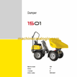
Brand: Wacker Neuson
Model: 1501 Dumper
Type of Document: Service Manual
$ 45
1 Operation
1.1 Information on this service manual
1.2 Identification of warnings and dangers
1.3 Designated use and exemption from liability
1.4 Type labels and component numbers
1.5 Machine overview 1501 D
1.6 Machine overview 1501H
1.7 Machine overview 1501S
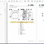
1.8 Operating equipment overview
1.9 Operating equipment (legend)
1.10 Maintenance prop, model 1501
1.11 Maintenance prop, model 1501S
1.12 Center-pivot prop, model 1501/1501S
1.13 Telematic
2 Technical data
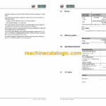
2.1 Chassis
2.2 Engine
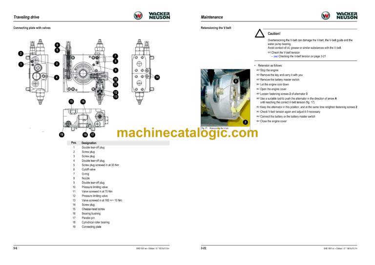
2.3 Traveling drive
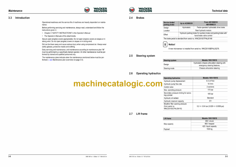
2.4 Brakes
2.5 Steering system
2.6 Operating hydraulics
2.7 Lift frame
2.8 Machine travel specifications
2.9 Electrical system (up to AC000101)
2.10 Electrical system (from AB150001H/150002D)
2.11 Tires
2.12 Noise levels
2.13 Vibration
2.14 Coolant compound table
2.15 General tightening torques
2.16 Dimensions model 1501
2.17 Dimensions model 1501S
3 Maintenance
3.1 Fluids and lubricants
3.2 Maintenance plan (overview)
3.3 Introduction
3.4 Fuel system
3.5 Engine lubrication system
3.6 Cooling system
3.7 Air filter
3.8 V-belt
3.9 Hydraulic system
3.10 Lubrication points 1501H (high-tip skip)
3.11 Lubrication points 1501S (swivel skip)
3.12 Tire maintenance
3.13 Changing wheels
3.14 Electrical system
3.15 Battery
3.16 Battery master switch
3.17 General maintenance
4 Engine
4.1 Engine overview 3TNE74 (up to AC000335)
4.2 Fuel system (up to AC000335)
4.3 Engine overview 3TNV76 – XNSV (from AB150001H/AB150002D)
4.4 Fuel system (from AB150001H/AB150002D)
4.5 Checking and adjusting valve clearance
4.6 Tightening order for cylinder head bolts
4.7 Checking the injection nozzles
4.8 Checking the nozzle jet
4.9 Fuel injection time (up to AC000335)
4.10 Fuel injection time (from AB150001H/AB150002D)
4.11 Adjusting engine speed
4.12 Compression
4.13 Checking the coolant thermostat
4.14 Checking the thermal switch
4.15 Oil pressure switch
4.16 Checking the coolant circuit
4.17 Engine malfunctions
5 Traveling drive
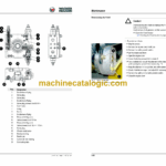
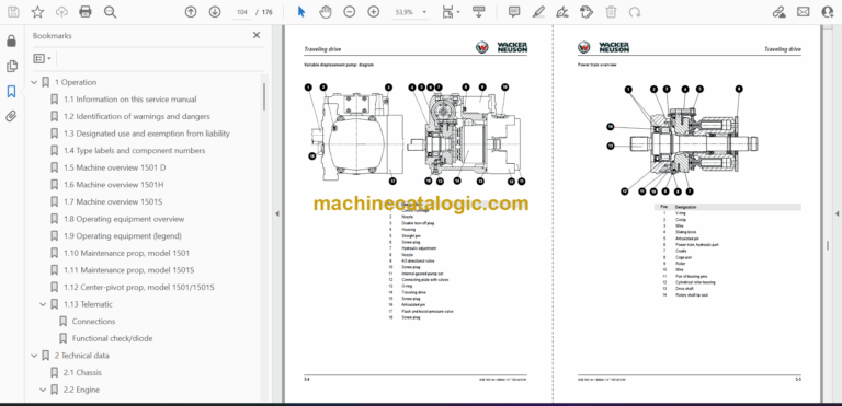
5.1 Variable displacement pump A10VG45DA
5.2 Rear traveling drive (up to serial no. WNCD0105KPAL00316)
5.3 Front traveling drive (up to serial no. WNCD0105KPAL00316)
5.4 Traveling drive overview
5.5 Towing and transporting the machine
5.6 Test instructions
5.7 Traveling drive (from serial no. WNCD0105JPAL00317)
6 Brakes
6.1 Brake circuit up to serial no. AC000241
6.2 Brake circuit from serial no. AC000242
7 Steering system
7.1 Steering circuit
7.2 Steering unit: diagram
7.3 Steering unit connections
7.4 Steering unit overview
8 Hydraulic system
8.1 Control valve connections (overview)
8.2 Test instructions
8.3 1501 diagram up to serial no. AC000241
8.4 1501 diagram up to serial no. AC000241 (legend)
8.5 1501 diagram from AB150001H/AB150002D
8.6 1501 diagram from AB150001H/AB150002D (legend)
8.7 1501S diagram up to serial no. AC000241
8.8 Diagram 1501S (legend)
8.9 1501S diagram up to serial no. AC000242
8.10 1501S diagram from serial no. AC000242 (legend)
8.11 Hydraulics diagram 1501 (up to serial no. AC000241)
8.12 Hydraulics diagram 1501 (from serial no. AB150001H/AB150002D)
8.13 Hydraulics diagram 1501S (up to serial no. AC000241)
8.14 Hydraulics diagram 1501S (from serial no. AC000242)
9 Electrical system
9.1 Ohm’s Law (current, voltage, resistance); power
9.2 Measuring equipment, measuring methods
9.3 Relays
9.4 Electric units
9.5 Fuse box in instrument panel (up to AC000335)
9.6 Instrument panel overview
9.7 Fuse box on instrument panel (from AB150001H/AB150001D)
9.8 Instrument panel overview (from AB150001H/AB150001D)
9.9 Main wiring harness legend
9.10 Main wiring harness
9.11 Main wiring harness legend
9.12 Main wiring harness
9.13 Engine wiring harness from AB150001H/AB150002D (legend)
9.14 Engine wiring harness from AB150001H/AB150002D
9.15 Rotating beacon wiring harness
9.16 Battery lead
9.17 Trailer socket wiring harness
9.18 Wiring diagram legend (up to serial no. AC000241)
9.19 Wiring diagram (up to serial no. AC000241)
9.20 Wiring diagram legend (serial no. AC000242 to AC000335)
9.18 Wiring diagram (serial no. AC000242 to AC000335)
9.19 Wiring diagram legend (serial no. AB150001H / AB150002D to WNCD0105HPAL00275)
9.20 Wiring diagram (serial no. AB150001H / AB150002D to WNCD0105HPAL00275)
9.21 Wiring diagram legend (from serial no. WNCD0105EPAL00276)
9.22 Wiring diagram (from serial no. WNCD0105EPAL00276)
