Format: PDF (Printable Document)
File Language: English
File Pages: 204
File Size: 11.05 MB (Speed Download Link)
Brand: Wacker Neuson
Model: 501S Compact Loader
Type of Document: Service Manual
$ 45
1 Operation
1.1 Notices on this service manual
1.2 Identification of warnings and dangers
1.3 Designated use and exemption from liability
1.4 Type labels and component numbers
1.5 Machine overview
1.6 Cab, model 501s with mechanical pilot control (overview)
1.7 Cab, model 501s with mechanical pilot control (legend)
1.8 Model 501s cab overview (hydraulic pilot control)
1.9 Cab, model 501s with hydraulic pilot control (legend)
1.10 Instrument panel overview
1.11 Instrument panel legend
1.12 Engine compartment: overview
1.13 Engine cover (open): overview
1.14 Chassis overview
1.15 Raising/lowering the cab
2 Specifications
2.1 Chassis
2.2 Engine
2.3 Travelling drive
2.4 Brakes
2.5 Work hydraulics
2.6 Pilot control
2.7 Additional control circuit
2.8 Electrical system
2.9 Tyres
2.10 Noise levels
2.11 Vibration
2.12 Coolant compound table
2.13 Dimensions
2.14 Model-specific tightening torques
2.15 General tightening torques
3 Maintenance
3.1 Fluids and lubricants
3.2 Maintenance label
3.3 Maintenance plan (overview)
3.4 Service package
3.5 Introduction
3.6 Fuel system
3.7 Engine lubrication system
3.8 Cooling system
3.9 Air filter
3.10 V-belt
3.11 Pressure check
3.12 Test report
3.13 Hydraulic system
3.14 Travelling drive
3.15 Tyre maintenance
3.16 Lubrication work
3.17 Electrical system
3.18 General maintenance work
4 Engine
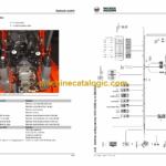
4.1 Engine 3TNV88-XNSS up to serial no. DB00692 (overview)
4.2 Fuel system
4.3 Checking and adjusting valve clearance
4.4 Tightening order for cylinder head bolts
4.5 Checking the injection nozzles
4.6 Checking the nozzle jet
4.7 Injection time
4.8 Adjusting engine speed
4.9 Compression
4.10 Checking the coolant thermostat
4.11 Checking the thermal switch
4.12 Oil pressure switch
4.13 Checking the coolant circuit
4.14 Engine 3TNV88-BDNSS from serial no. DC00738 (overview)
4.15 Fuel system
4.16 Removing the valve cover
4.17 Checking and adjusting valve clearance
4.18 Tightening order for cylinder head bolts
4.19 Checking the injection nozzles
4.20 Checking the nozzle jet
4.21 Injection time
4.22 Adjusting engine speed
4.23 Compression
4.24 Checking the coolant thermostat
4.25 Checking the thermal switch
4.26 Oil pressure switch
4.27 Checking the coolant circuit
4.28 Engine trouble
5 Hydraulic system
5.1 Danfoss MPT 025 hydraulic pump (mechanically pilot-controlled)
5.2 Hydraulic pump A10VG28 (hydraulically pilot-controlled)
5.3 Main valve block
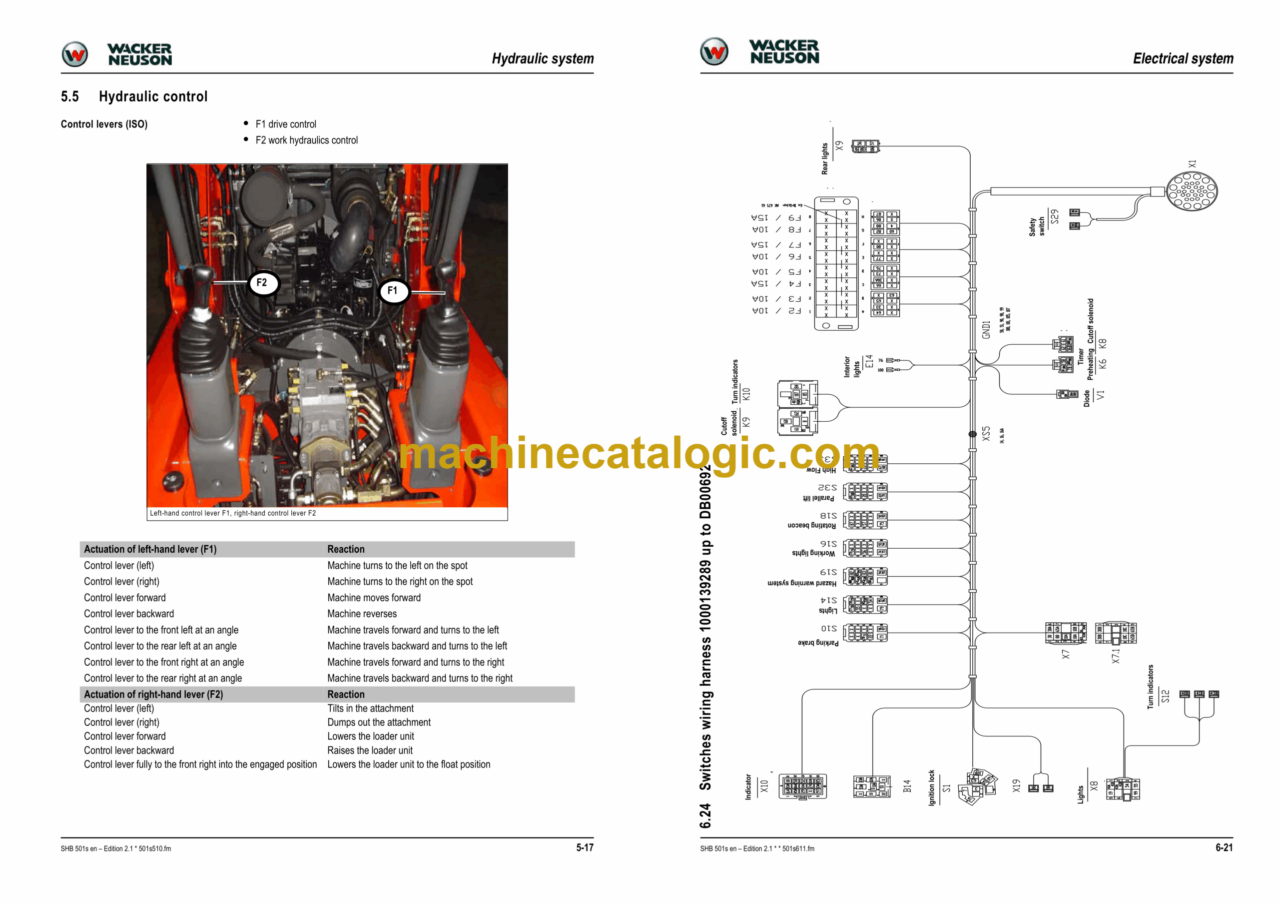
5.4 Mechanical controls
5.5 Hydraulic control
5.6 Travelling drive
5.7 Valves
5.8 Troubleshooting in the hydraulic system
5.9 Hydraulics diagram
5.10 Hydraulics diagram (legend)
5.11 Hydraulics diagram 501S A3
6 Electrical system
6.1 Ohm’s Law (current, voltage, resistance); power
6.2 Measuring equipment, measuring methods
6.3 Cable colour coding
6.4 Relays
6.5 Electric units
6.6 Fuse box in instrument panel
6.7 Main fuse box with relays
6.8 Relays
6.9 Socket
6.10 Control levers
6.11 Instrument panel overview
6.12 Switches (overview)
6.13 Alternator
6.14 Starter
6.15 Wiring diagram up to serial no. DB00167 (legend)
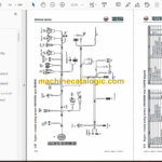
6.16 Wiring diagram up to serial no. DB00167
6.17 Wiring diagram from serial no. DB00168 (legend)
6.18 Wiring diagram from serial no. DB00168
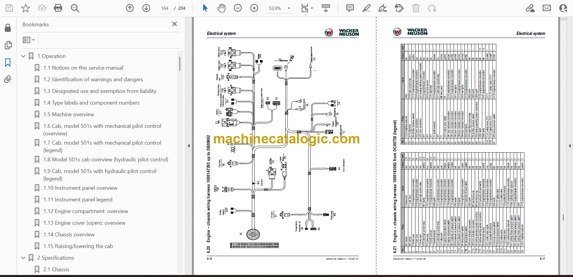
6.19 Engine – chassis wiring harness 1000147293 up to DB00692 (legend)
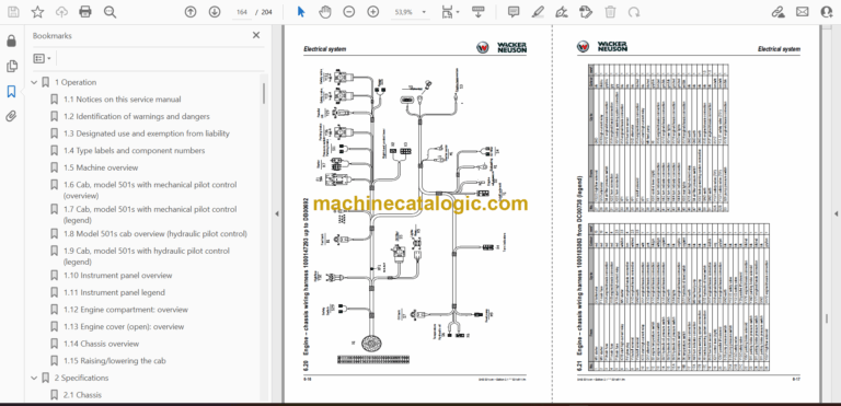
6.20 Engine – chassis wiring harness 1000147293 up to DB00692
6.21 Engine – chassis wiring harness 1000183063 from DC00738 (legend)
6.22 Engine – chassis wiring harness 1000183063 from DC00738
6.23 Switches wiring harness 1000139289 up to DB00692 (legend)
6.24 Switches wiring harness 1000139289 up to DB00692
6.25 Switches wiring harness 1000183064 from DC00738 (legend)
6.26 Switches wiring harness 1000183064 from DC00738
6.27 Rear lights wiring harness 1000147262 (option) up to DB00692
6.28 Wiring diagram A3 up to DB00167 (legend)
6.29 Wiring diagram A3 up to DB00167
6.30 Wiring diagram A3 from DB00168 (legend)
6.31 Wiring diagram A3 from DB00168
6.32 Engine – chassis A3 wiring harness 1000147293 up to DB00692 (legend)
6.33 Engine – chassis A3 wiring harness 1000147293 up to DB00692
6.34 Engine – chassis A3 wiring harness 1000183063 from DC00738 (legend)
6.35 Engine – chassis A3 wiring harness 1000183063 from DC00738
6.36 Switches A3 wiring harness 1000139289 up to DB00692 (legend)
6.37 Switches A3 wiring harness 1000139289 up to DB00692
6.38 Switches A3 wiring harness 1000183064 from DC00738 (legend)
6.39 Switches A3 wiring harness 1000183064 from DC00738
6.40 Rear lights wiring harness 1000147262 (option)
7 Options
7.1 Rear working light
7.2 BP-Biohyd SE 46
7.3 Panolin biodegradable oil
7.4 Immobilizer antitheft protection
7.5 Rotating beacon
7.6 Crane-handling bracket
7.7 FOPS roof level 2
7.8 Accelerator pedal
7.9 Inside rearview mirror
7.10 Comfort seat
7.11 Rearview mirror package
7.12 Backup warning system
7.13 Parallel bucket lift
7.14 Side window
7.15 Paint other than standard
7.16 Road travel certification
7.17 Airboss tyres
Leere Seite

