Format: PDF (Printable Document)
File Language: English
File Pages: 208
File Size: 11.01 MB (Speed Download Link)
Brand: Wacker Neuson
Model: 803, 803 DualPower Tracked Excavator
Type of Document: Service Manual
$ 45
Service manual
1 Operation
1.1 Notices on this service manual
1.2 Identification of warnings and dangers
1.3 Explanation of symbols and abbreviations
1.4 Warranty and liability
1.5 Labels
1.6 Machine overview (up to serial no. AI00966)
1.7 Machine overview (from serial no. AI00967)
1.8 Control stand overview (up to serial no. AI00814)
1.9 Control stand overview (from serial no. AI00815)
1.10 Display elements (overview)
1.11 Engine compartment overview (up to serial no. AI00814)
1.12 Engine compartment overview (from serial no. AI00815)
1.13 Battery master switch
2 Technical data
2.1 Chassis
2.2 Engine
2.3 Hydraulic system
2.4 Travel gear and swivel unit
2.5 Stabilizer blade
2.6 Electrical system
2.7 Noise levels
2.8 Vibration
2.9 Coolant compound table
2.10 Hose identification code
2.11 Model-specific tightening torques
2.12 General tightening torques
2.13 Dimensions model 803 (up to serial no. AI00966)
2.14 Dimensions model 803 with ROPS rollbar (from serial no. AI00967)
2.15 Dimensions model 803 without ROPS rollbar (from serial no. AI00967)
2.16 Lift capacity table 803 RD
2.17 Kinematics
3 Maintenance
3.1 Information on maintenance
3.2 Special tools
3.3 Fluids and lubricantse
3.4 Maintenance label
3.5 Maintenance plan (overview)
3.6 Fuel system
3.7 Engine lubrication system
3.8 Cooling system
3.9 Air filter (up to serial no. AI00875)
3.10 Air filter (from serial no. AI00876)
3.11 V-belt
3.12 Pressure check
3.1 Test report
3.14 Hydraulic system
3.15 Tracks
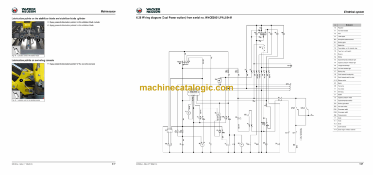
3.16 Lubrication points on boom (up to serial number AI00966)
3.17 Overview of lubrication points (from serial no. AI00967)
3.18 Electrical system
3.19 General maintenance
3.20 Preparatory work before taking out of service
3.21 Maintenance when out of service for a longer period of time
4 Engine
4.1 Overview of engine 3TNV70-VNS (Tier IV final up to 2012)
4.2 Fuel system
4.3 Checking and adjusting valve clearance
4.4 Tightening order for cylinder head bolts
4.5 Checking the injection nozzles
4.6 Checking the nozzle jet
4.7 Injection time
4.8 Adjusting engine speed
4.9 Compression
4.10 Checking the coolant thermostat
4.11 Checking the thermal switch
4.12 Oil pressure switch
4.13 Checking the coolant circuit
4.14 Engine malfunctions
4.15 Overview of engine 3TNV74F-SNNS (Tier IV final from 2012)
4.16 Fuel system
4.17 Cooling system
4.18 Altitude-dependent output reduction
4.19 Checking and adjusting valve clearance
4.20 Tightening order for cylinder head bolts
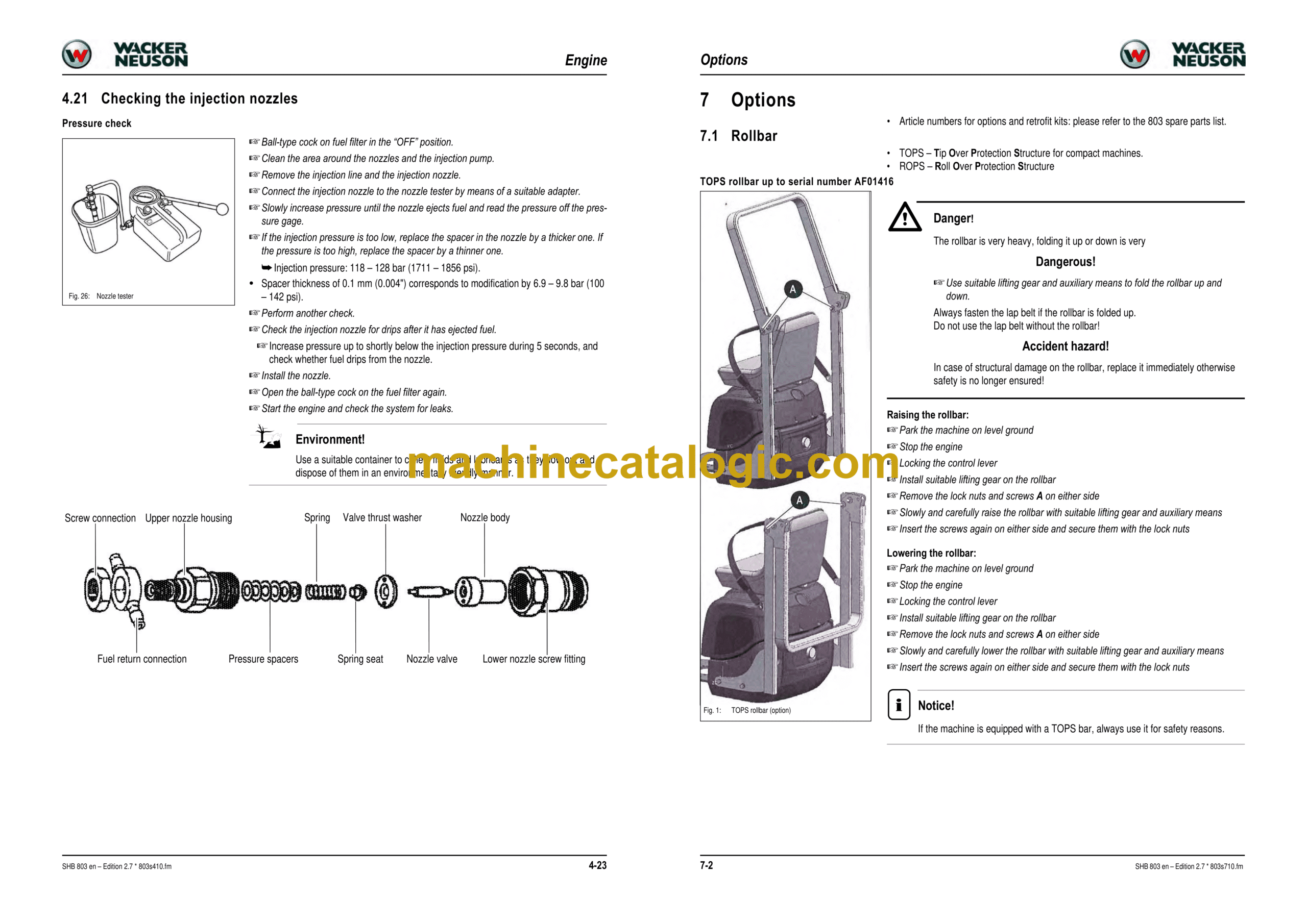
4.21 Checking the injection nozzles
4.22 Checking the nozzle jet
4.23 Injection time
4.24 Removing and installing the injection pump
4.25 Measuring and adjusting the engine speed
4.26 Compression
4.27 Checking the coolant thermostat
4.28 Checking the temperature sensor
4.29 Oil pressure switch
4.30 Checking the coolant circuit
4.31 Cleaning the cooling water channels
4.32 Coolant and fuel hoses
4.33 Crankcase vent
4.34 Replacing the glow plugs
4.35 Engine malfunctions
5 Hydraulic system
5.1 Hydraulic pump PGP505B0050CA1H2NJ7J5C-505A00 (Tier IV final up to 2012)
5.2 Hydraulic pump PGP505B0040CA1H2NJ7J5C-505A0040XB1J5B1B1 (Tier IV final from 2012)
5.3 Main valve block
5.4 Travel drive
5.5 Swivel unit
5.6 Swivel joint
5.7 Mechanical control
5.8 Malfunctions in the hydraulic system
5.9 Plastic trims
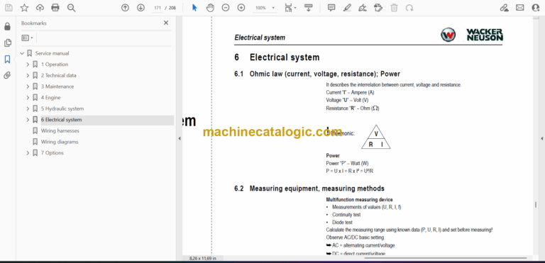
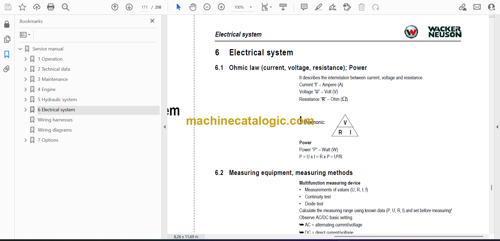
6 Electrical system
6.1 Ohmic law (current, voltage, resistance); Power
6.2 Measuring equipment, measuring methods
6.3 Cable color coding
6.4 Relays
6.5 Electrical system
6.6 Control lever push button
6.7 Working light
6.8 Dynamo
6.9 Rectifier
6.10 Starter
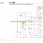
6.11 Engine wiring harness legend (TIER IV final up to 2012)
6.12 E n g i n e w i r i n g h a r n e s s ( Tier IV final up to 2012)
6.13 Engine wiring harness legend (Tier IV final from 2012)
6.14 E n g i n e w i r i n g h a r n e s s ( Tier IV final from 2012)
6.15 Wiring harness for indicators (up to serial number WNCE0801TPAL00923)
6.16 Wiring harness for indicators (from serial number WNCE0801PPAL00924)
6.17 Cable power supply for the operating hour meter
6.18 Traveling signal wiring harness (option)
6.19 Horn wiring harness
6.20 Battery lead
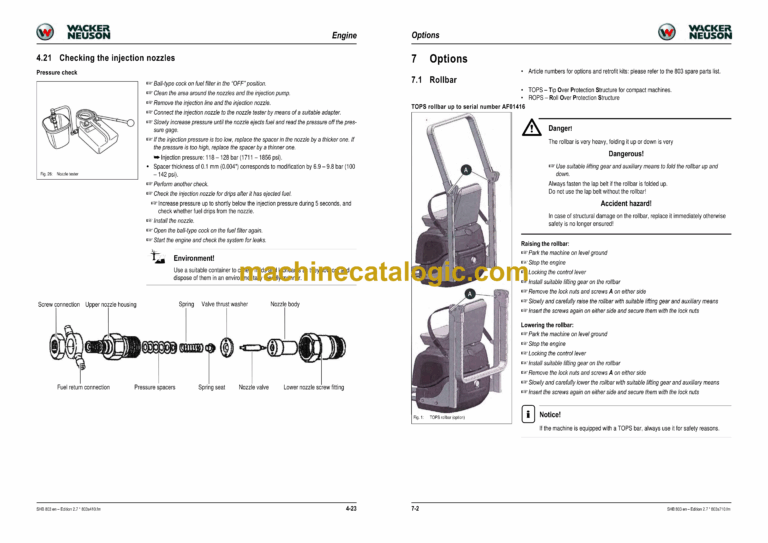
6.21 Indicating instrument wiring harness (Dual Power option)
6.22 Legend of engine/chassis wiring harness (Dual Power option)
6.23 Engine/chassis wiring harness (Dual Power option)
6.24 Seat console wiring harness
Wiring harnesses
Wiring diagrams
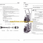
7 Options
7.1 Rollbar
7.2 ISO/SAE changeover (option)
7.3 Travel signal (option)
7.4 Telematic
7.5 Zero-emission Dual Power drive

