Format: PDF (Printable Document)
File Language: English
File Pages: 404
File Size: 14.98 MB (Speed Download Link)
Brand: Wacker Neuson
Model: ET35, EZ36 Tracked Excavator
Type of Document: Service Manual
$ 45
Table of Contents
1 General
1.1 Service manual
1.2 Warranty and liability
1.3 Warning notices
1.4 Labels
1.5 Machine overview
1.6 Overview of the engine compartment Tier III
1.7 Overview of the engine compartment Tier IV
1.8 Valve compartment overview
1.9 Overview of the tank room
1.10 Battery master switch
1.11 Towing
1.12 Crane-lifting
1.13 Towing the vehicle
1.14 Loading the vehicle
1.15 Transporting the vehicle
2 Technical data
2.1 Engine Yanmar
2.2 Traveling drive
2.3 Tracks
2.4 Work hydraulics.
2.5 Maximum speed
2.6 Traction force
2.7 Cylinder speeds
2.8 Electrical system
2.9 Powertilt (option)
2.10 Auxiliary hydraulics performance measurement
2.11 Payload/stability
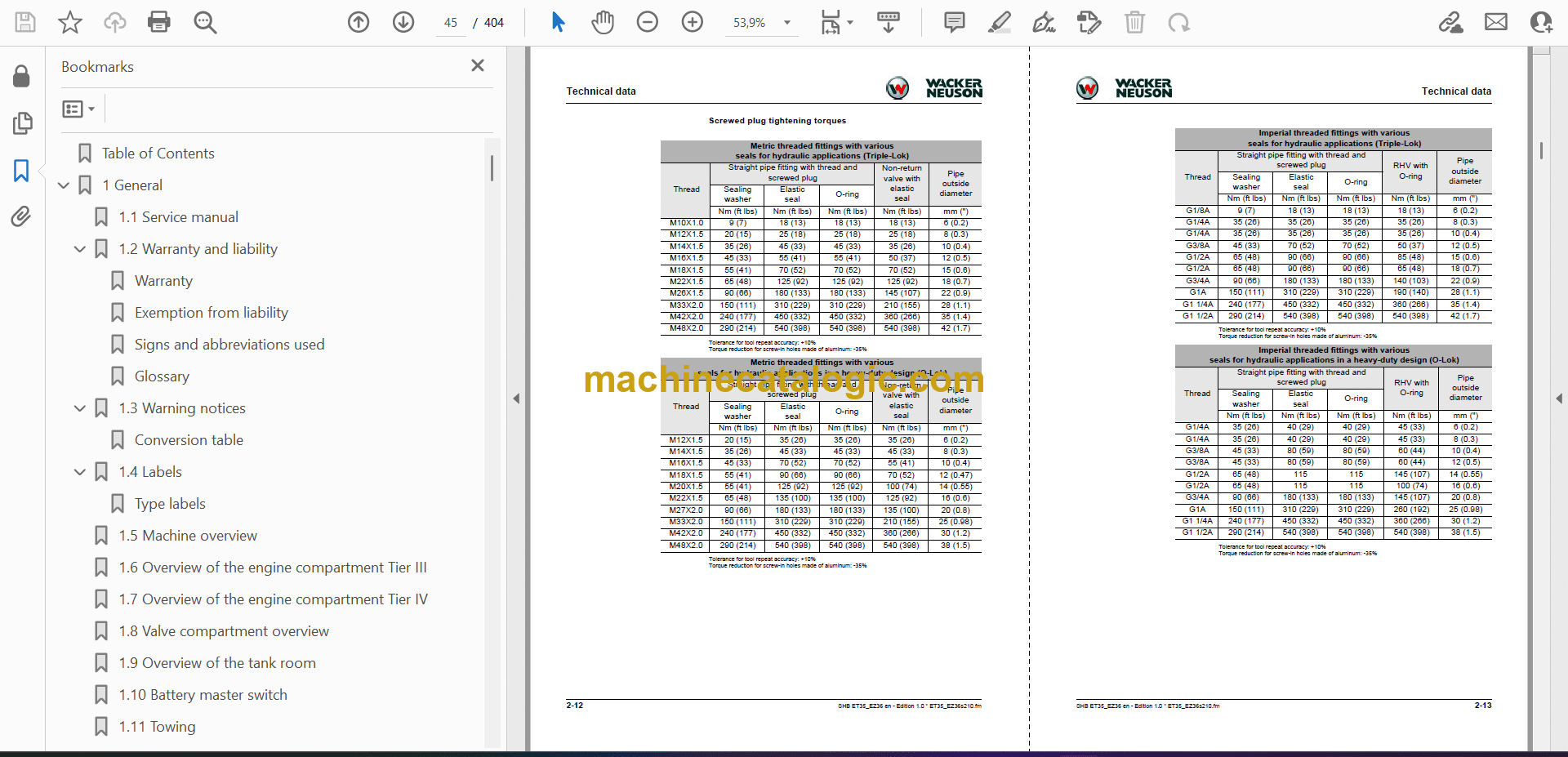
2.12 Tightening torques
2.13 Hose identification code
2.14 Coolant
2.15 Weights
2.16 Excavator forces
2.17 Dimensions
2.18 Kinematics
2.19 Wear limits
2.20 Overload setting (Tier IV)
3 Maintenance
3.1 Information on maintenance
3.2 Special tools
3.3 Fluids and lubricants
3.4 Important information regarding operation with biodegradable hydraulic oil
3.5 Maintenance plan
3.6 Parking the machine
3.7 Maintenance accesses
3.8 Cabin
3.9 General engine information
3.10 Fuel system
3.11 Engine lubrication system
3.12 Cooling system
3.13 Air filter
3.14 Washer system
3.15 V-belt
3.16 Exhaust gas cleaning system
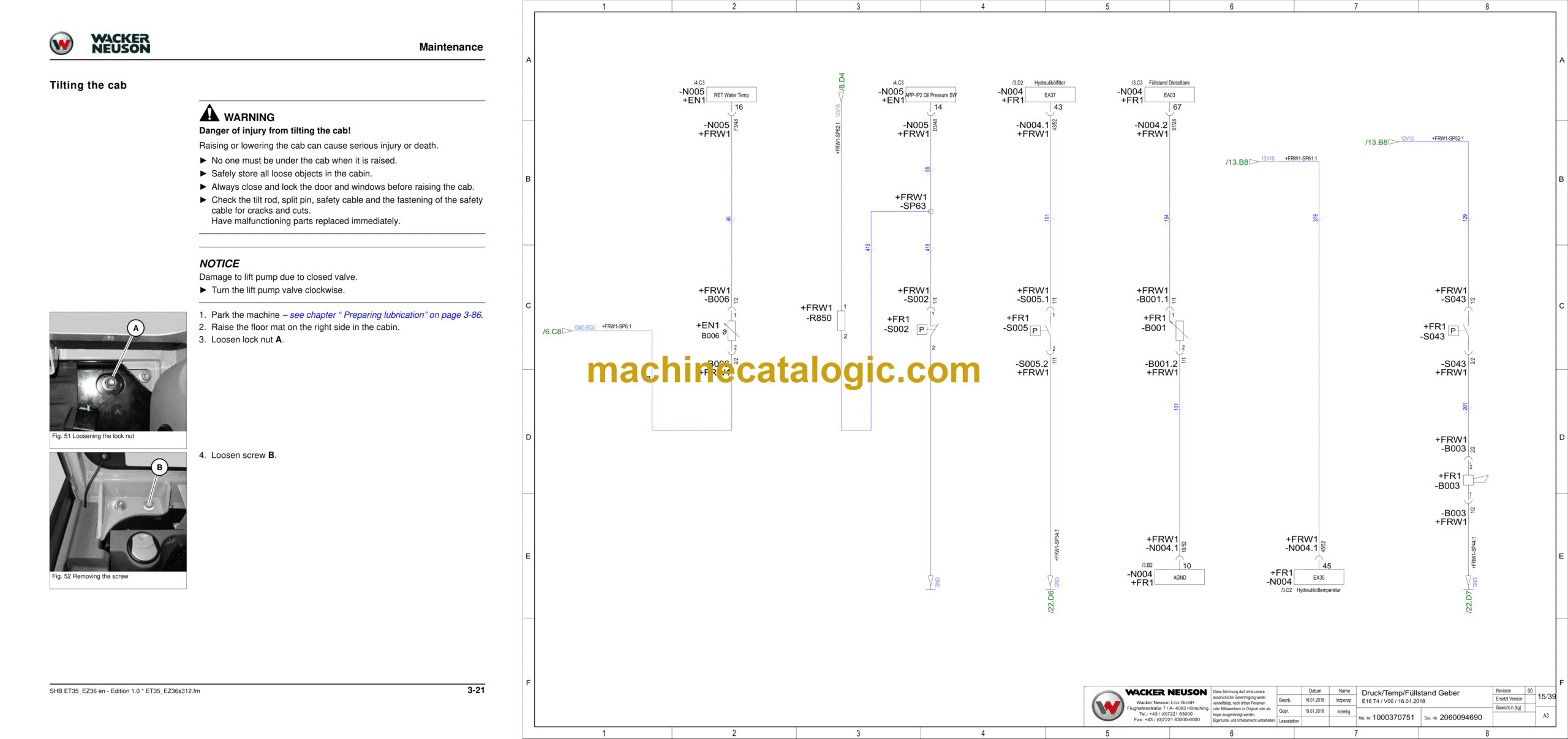
3.17 Hydraulic system
3.18 Checking the hydraulic system pressure
3.19 Test report
3.20 Traveling drive
3.21 Tracks
3.22 Measuring live ring tolerance
3.23 Maintenance of attachments
3.24 Lubrication work
3.25 Electrical system
3.26 Cleaning and maintenance
3.27 Resetting the maintenance meter
4 Engine
4.1 Yanmar 3TNV88-BPWN (Tier III)
4.2 Yanmar 3TNV88F-EPWN (Tier IV)
4.3 Fuel system
5 Hydraulic system
5.1 Overview of components
5.2 Hydraulic oil tank L042
5.3 Work pump T003 and control oil unit C006
5.4 Main control block C001
5.5 Drive counterbalancing system
5.6 Drive (T011, T012)
5.7 8-channel swivel joint (L017)
5.8 10-channel swivel joint for option VDS (L017)
5.9 Swivel unit (T015)
5.10 Pilot valves
5.11 Hose burst valve 1(L062), load-retaining valve 1 (L001) option
5.12 Hose burst valve 2 (L063)
5.13 Tank return for hammer operation (L056)
5.14 Reverse travel manifold block (L046)
5.15 Distributor unit 1 (L048)
5.16 Changeover valve SAE / ISO control option (L039)
5.17 Changeover valve VDS (C032) – Option
5.18 HSWS valve (C017) – option
5.19 Floating position valve (C045) – option
5.20 Auxiliary hydraulics performance measurement
5.21 Test specifications for measuring cylinder speeds
6 Electrical system
6.1 Ohmic law (current, voltage, resistance); power
6.2 Measuring equipment, measuring methods
6.3 Cable color coding
6.4 Relays
6.5 Electrical system
6.6 Control equipment
6.7 Sensors
6.8 CAN-Bus
7 Local position of the wiring harnesses
7.1 General information about the wiring harnesses
7.2 Main wiring harness Tier III
7.3 Main wiring harness Tier IV
7.4 Wiring harness for cab switch
7.5 Wiring harness for cab headlight
7.6 Cabin roof wiring harness
7.7 Wiring harness for canopy switch
7.8 Canopy headlight wiring harness (option)
7.9 Additional wiring harness VDS-HSWS (Tier III)
7.10 Negative battery cable
7.11 Cable for foot-operated tip switch of hydraulic quickhitch
7.12 Positive battery cable (1050 mm)
7.13 Positive cable (700 mm)
7.14 Cable for safe load indicator (Tier III)
7.15 Cable for overload pressure sensor (Tier IV)
7.16 Wiring harness for proportional controls (Tier III)
7.17 Cable for dozer blade lever (Tier IV)
7.18 Intermediate cable for joystick (Tier IV)
7.19 Cable display (Tier IV)
7.20 Boom headlight cable
7.21 Cable for external start terminal
8.1 Legend for wiring harness for cab switch
8.2 Wiring harness for cab switch
8.3 Wiring harness for cab headlight
8.4 Wiring harness for cab headlight roof
8.5 Legend for wiring harness for canopy switch
8.6 Wiring harness for canopy switch
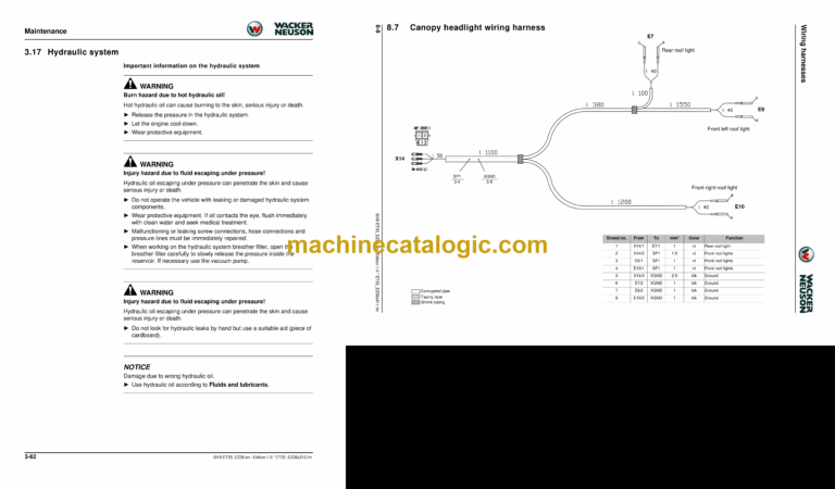
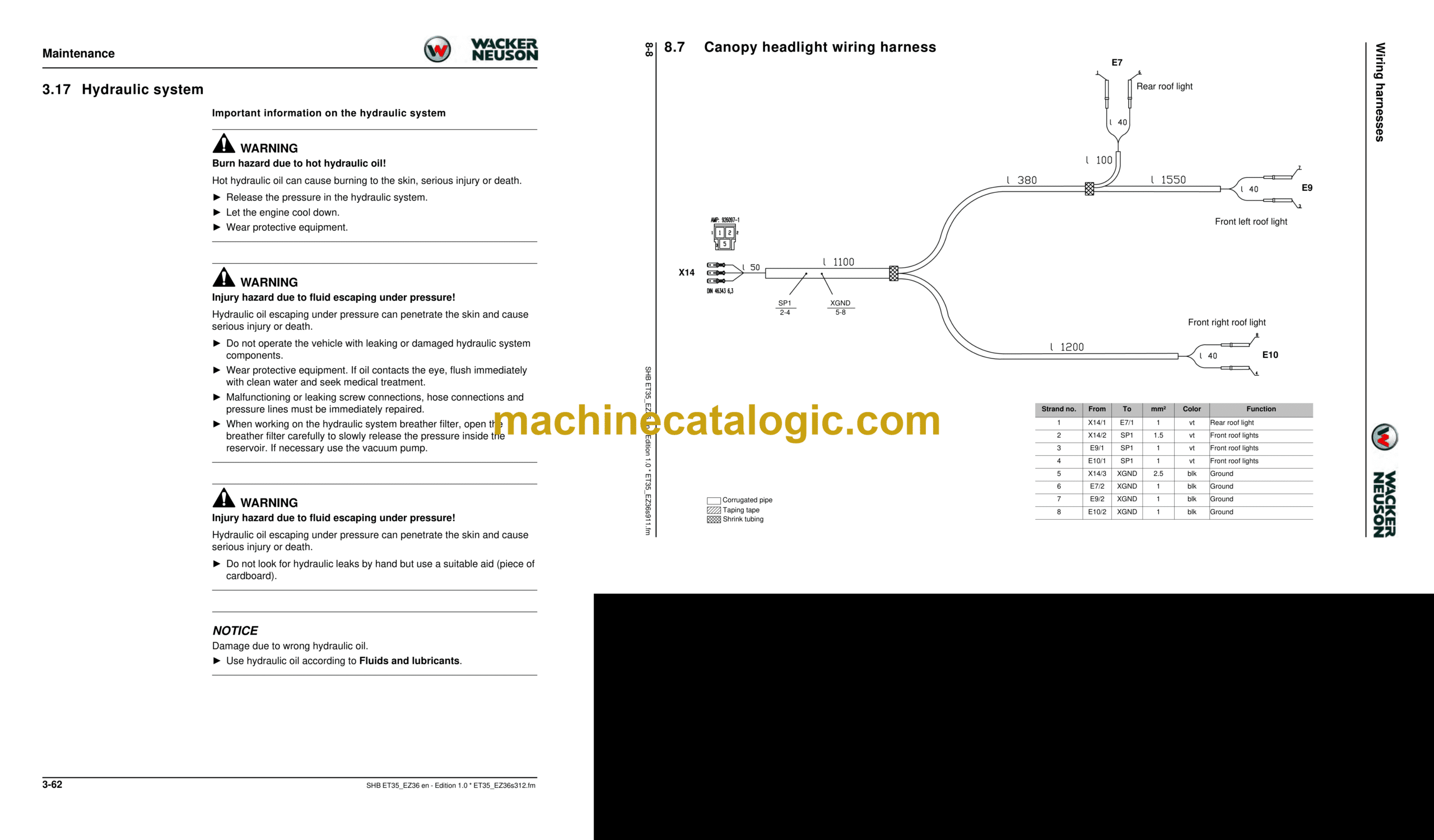
8.7 Canopy headlight wiring harness
8.8 Connection list for additional wiring harness VDS-HSWS (Tier III)
8.9 Additional wiring harness VDS-HSWS (Tier III)
8.10 Cable for HSWS foot-operated button
8.11 Connection list for safe load indicator wiring harness (Tier III)
8.12 Safe load indicator wiring harness (Tier III)
8.13 Connection list for cable for overload pressure sensor (Tier IV)
8.14 Cable for overload pressure sensor (Tier IV)
8.15 Cable for proportional controls (Tier III)
8.16 Connection list for cable for dozer blade lever (Tier IV)
8.17 Cable for dozer blade lever (Tier IV)
8.18 Connection list for cable for display (Tier IV)
8.19 Cable display (Tier IV)
8.20 Connection list for cable for boom headlight
8.21 Boom headlight cable
8.22 Connection list for intermediate cable for joystick (Tier IV)
8.23 Intermediate cable for joystick (Tier IV)
8 Wiring harnesses
9 Diagrams
10 Air conditioning
10.1 Specific safety instructions
10.2 Overview
10.3 Air conditioning components
10.4 Filling up the air conditioning system
10.5 Malfunctions
11 Telematic
11.1 Connections
11.2 Functional check/LED
12 Diagnosis code list
12.1 Diagnosis code list (SPN)
Index
E3D-2060094690_Engineering_SLP_T3.pdf
Stromlaufplan | E16 T3 Stromlaufplan
E3D-2060094690_Engineering_SLP_T4.pdf
Stromlaufplan | E16
Leere Seite


