Format: PDF (Printable Document)
File Language: English
File Pages: 252
File Size: 15.00 MB (Speed Download Link)
Brand: Wacker Neuson
Model: EZ17 Tracked Excavator
Type of Document: Service Manual
$ 45
1 Operation
1.1 Notices on this service manual
1.2 Identification of warnings and dangers
1.3 Explanation of symbols and abbreviations
1.4 Warranty and liability
1.5 Labels
1.6 Machine overview
1.7 Canopy
1.8 Engine compartment
1.9 Valve compartment
1.10 Pump compartment
1.11 Overview of components
1.12 Display element and switches
1.13 Indicator lights and warning lights (overview)
1.14 Operating hydraulics
1.15 Cabin/control stand
1.16 Control lever base
1.17 Accelerator actuation
1.18 High speed
1.19 Brakes
1.20 Protective structures
1.21 Checking the threaded fittings of the canopy
1.22 Emergency lowering
1.23 Releasing the pressure in the operating hydraulics
1.24 Connecting and disconnecting hydraulic couplings
1.25 Hydraulic connections
1.26 Parking the machine
2 Specifications
2.1 Models and trade names
2.2 Engine
2.3 Fuel injection pump
2.4 Travelling drive/axles
2.5 Brakes
2.6 Tracks
2.7 Steering system
2.8 Hydraulic system
2.9 Speed
2.10 Coolant compound table
2.11 Ground clearance/ground pressure
2.12 Excavator forces
2.13 Ram speeds
2.14 Vibration
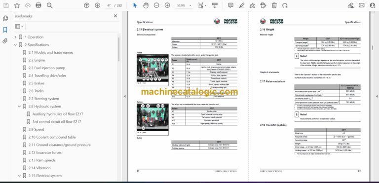
2.15 Electrical system
2.16 Weight
2.17 Noise emissions
2.18 Powertilt (option)
2.19 Tightening torques
2.20 Payload/lift capacity
2.21 Dimensions
2.22 Kinematics
3 Maintenance
3.1 Important information on maintenance
3.2 Service package
3.3 Fluids and lubricants
3.4 Maintenance label
3.5 Maintenance plan
3.6 Overview of maintenance areas
3.7 Maintenance accesses
3.8 Removing/installing the canopy
3.9 Fuel system
3.10 Engine lubrication system
3.11 Cooling system
3.12 Air filter
3.13 Heating, ventilation and air conditioning system
3.14 Washer system
3.15 V-belt
3.16 Pressure check
3.17 Test report
3.18 Hydraulic system
3.19 Pilot control filter
3.20 Axles/travelling drive
3.21 Tyres/tracks
3.22 Maintenance of attachments
3.23 Maintenance of options
3.24 Lubrication work
3.25 Lubrication plan
3.26 Electrical system
3.27 Cleaning and maintenance work
3.28 Decommissioning and putting the machine back into operation
3.29 Final decommissioning of machine
3.30 Resetting the maintenance meter
4 Engine
4.1 Overview of engine 3TNV76-NNS (TIER IV final up to 2012)
4.2 Fuel system
4.3 Cooling system
4.4 Checking and adjusting valve clearance
4.5 Tightening order for cylinder head bolts
4.6 Checking the injection nozzles
4.7 Checking the nozzle jet
4.8 Injection time
4.9 Removing and installing the injection pump
4.10 Measuring and adjusting the engine speed
4.11 Compression
4.12 Checking the coolant thermostat
4.13 Checking the temperature sensor
4.14 Oil pressure switch
4.15 Checking the coolant circuit
4.16 Cleaning the cooling water channels
4.17 Coolant and fuel hoses
4.18 Crankcase vent
4.19 Replacing the glow plugs
4.20 Engine trouble
4.21 Overview of engine 3TNV80F-SNNS (TIER IV final from 2012)
4.22 Fuel system
4.23 Cooling system
4.24 Altitude-dependent output reduction
4.25 Checking and adjusting valve clearance
4.26 Tightening order for cylinder head bolts
4.27 Checking the injection nozzles
4.28 Checking the nozzle jet
4.29 Injection time
4.30 Removing and installing the injection pump
4.31 Measuring and adjusting the engine speed
4.32 Compression
4.33 Checking the coolant thermostat
4.34 Checking the temperature sensor
4.35 Oil pressure switch
4.36 Checking the coolant circuit
4.37 Cleaning the cooling water channels
4.38 Coolant and fuel hoses
4.39 Crankcase vent
4.40 Replacing the glow plugs
4.41 Engine trouble
5 Hydraulic system
5.1 How the load-sensing system works
5.2 Overview of components
5.3 Hydraulic pump
5.4 Main valve block
5.5 Travelling drive
5.6 Swivel unit
5.7 Swivel joint
5.8 Valves
5.9 Breather filter (hydraulic oil tank)
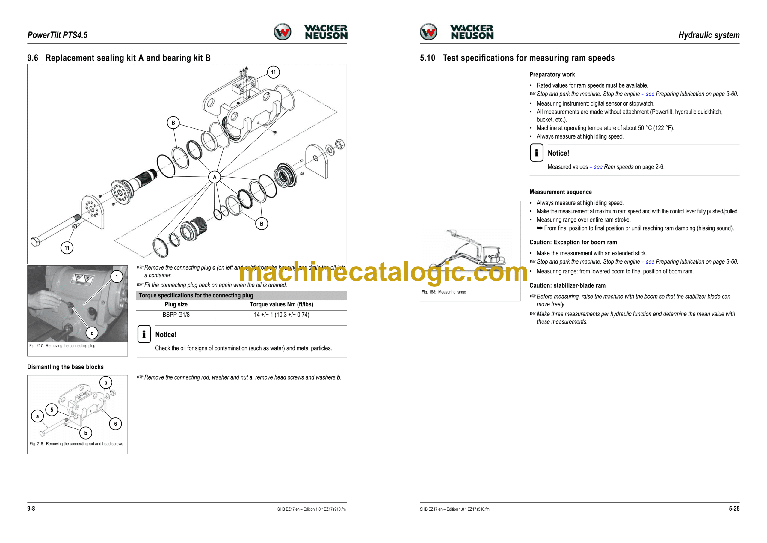
5.10 Test specifications for measuring ram speeds
5.11 Troubleshooting the hydraulic system
6 Electrical system
6.1 Ohm’s Law (current, voltage, resistance); power
6.2 Measuring equipment, measuring methods
6.3 Relays
6.4 Electrical components
6.5 Main wiring harness legend
6.6 Main wiring harness
6.7 Proportional controls wiring harness (option)
6.8 Travelling signal wiring harness (option)
7 Diagrams
7.1 Hydraulics diagram (legend)
7.2 Hydraulics diagram
7.3 Hydraulics diagram (options)
7.9 Wiring diagram (legend)
7.10 Wiring diagram part 1
7.11 Wiring diagram part 2
8 Options
8.1 Counterweight
8.2 Long stick
8.3 Safe load indicator
8.4 Electro-proportional controls
8.5 3rd control circuit – AUX II
8.6 Hydraulic quickhitch valve
8.7 Grab control circuit
8.8 Hose burst valve
8.9 Drive interlock
8.10 Engine oil service valve
8.11 Telematic
9 PowerTilt PTS4.5
9.1 General instructions
9.2 Tools
9.3 Separating the bucket or equipment from the PowerTilt swivel device
9.4 Separating the PowerTilt swivel device from the machine
9.5 Individual components
9.6 Replacement sealing kit A and bearing kit B
9.7 Lubrication and tests
9.8 Replacing the decompression valve
9.9 Securing the PowerTilt swivel device on the machine
9.10 Fitting a bucket or equipment onto the PowerTilt swivel device
9.11 Adjusting the play on the PowerTilt
9.12 Troubleshooting


