Format: PDF (Printable Document)
File Language: English
File Pages: 216
File Size: 22.88 MB (Speed Download Link)
Brand: Wacker Neuson
Model: LTN6, LTN8 Light Tower
Type of Document: Repair Manual
$ 45
Foreword
1 Safety Information
1.1 Signal Words Used in this Manual
1.2 Machine Description and Intended Use
1.3 Safety Guidelines for Operating the Machine
1.4 Lamp Safety
1.5 Operator Safety while Using Internal Combustion Engines
1.6 Safety Guidelines for Towing the Machine
1.7 Service Safety
2 Operation
2.1 Starting
2.2 Stopping
2.3 Raising the Tower (Manual Winch System)
2.4 Lowering the Tower (Manual Winch System)
2.5 Raising the Tower (Power Winch System)
2.6 Lowering the Tower (Power Winch System)
3 Troubleshooting Engine Starting (no crank, no start)
3.1 Preparing for Diagnostic Procedures
3.2 Troubleshooting Sequence
3.3 Checking the Battery and Ground Wiring
3.4 Checking the Key Switch and Power to the Starter Solenoid
4 Troubleshooting Engine Starting (crank, no start)
4.1 Troubleshooting Sequence
4.2 Checking the Key Switch
4.3 Checking the 15A Fuse
4.4 Checking the Shut-down Relay
4.5 Checking the Diode
4.6 Checking Power to the Fuel Solenoid
4.7 Checking Power to the Glow Plugs
4.8 Checking a Glow Plug
5 Troubleshooting Engine Start (starts, then shuts down)
5.1 Preparing for Diagnostic Procedures
5.2 Troubleshooting Sequence
5.3 Checking the Oil Switch
5.4 Checking the Temperature Switch
6 Troubleshooting Engine Starting (no crank, no start)
6.1 Preparing for Diagnostic Procedures
6.2 Troubleshooting Sequence
6.3 Checking the Battery and Ground Wiring
6.4 Checking Power to the Starter Solenoid and to the Controller
7 Troubleshooting Engine Starting (crank, no start)
7.1 Preparing for Diagnostic Procedures
7.2 Troubleshooting Sequence
7.3 Checking the 15A Fuse
7.4 Checking Power to the Fuel Solenoid
7.5 Checking Power to the Glow Plugs
7.6 Checking a Glow Plug
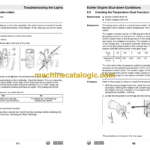
8 Kohler Engine Shut-down Conditions
8.1 List of Kohler Engine Shut-down Conditions
8.2 Diagnosing the Oil Pressure Circuit
8.3 Checking the Temperature (Dual Function) Switch
8.4 Clearing a Recharging System Fault
8.5 Checking the Air Restriction Indicator Switch
9 Troubleshooting Engine Starting (no crank, no start)
9.1 Preparing for Diagnostic Procedures
9.2 Troubleshooting Sequence
9.3 Checking the Battery and Ground Wiring
9.4 Checking the Key Switch and Power to the Starter Solenoid
10 Troubleshooting Engine Starting (crank, no start)
10.1 Preparing for Diagnostic Procedures
10.2 Troubleshooting Sequence
10.3 Checking the 15A Fuse
10.4 Checking Power to the Fuel Solenoid
10.5 Checking the Shut-down Timer Relay
10.6 Checking the Temperature Switch
10.7 Checking a Glow Plug
10.8 Checking the Oil Pressure Switch
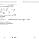
11 Troubleshooting the Lights
11.1 Preparing for Diagnostic Procedures
11.2 Determining Where to Start
11.3 Checking Engine RPM
11.4 Checking Voltage at the Main Terminal Strip
11.5 Checking the Circuit Breakers
11.6 Checking Power to the Ballast Terminal Strip(s)
11.7 Checking a Ballast Transformer
11.8 Checking a Ballast Capacitor
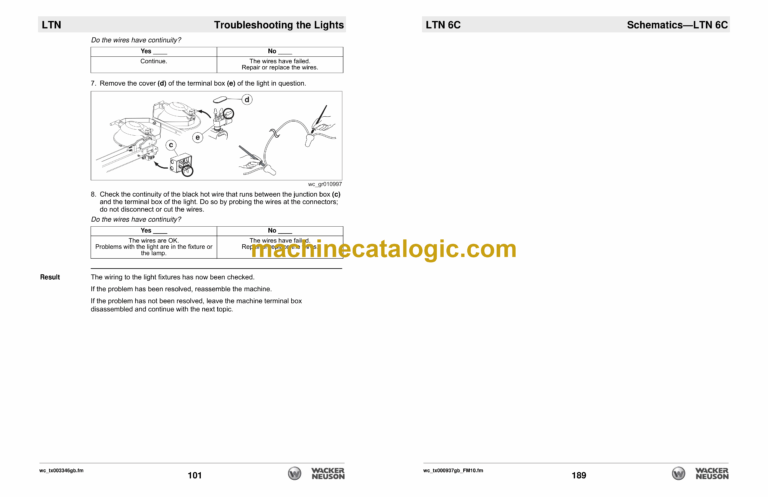
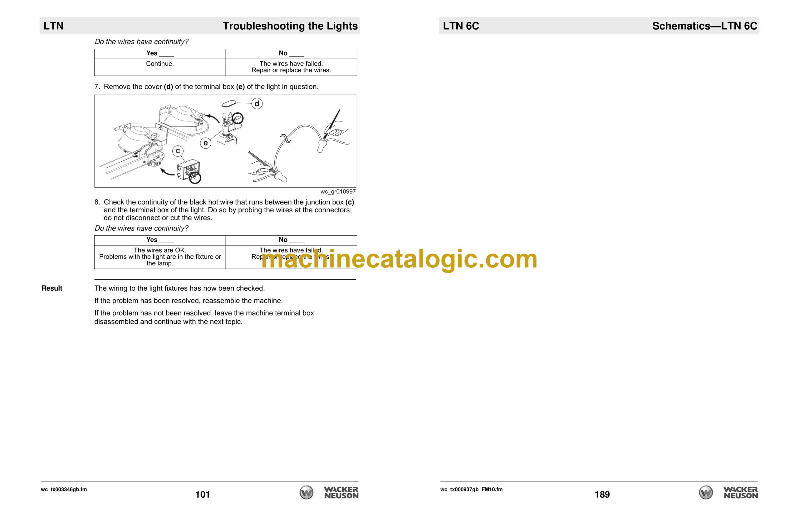
11.9 Checking the Wiring to the Light Fixture(s)
11.10 Checking a Light Fixture
11.11 Restoring Rotor Magnetism (Flashing) / Checking Rotor Winding
11.12 Checking the Excitation Capacitor
11.13 Checking the Stator Windings
11.14 Removing the Stator
11.15 Checking the Diodes (older)
11.16 Replacing a Diode (older)
11.17 Checking the Diodes (newer)
11.18 Replacing a Diode (newer)
11.19 Checking the Rotor Windings
12 Troubleshooting the Power Winch
12.1 Troubleshooting the Power Winch
12.2 Replacing the Cable and Power Winch
13 Disassembly and Reassembly
13.1 Tools Required for Disassembly/Assembly Procedures
13.2 Information Regarding Replacement Parts
13.3 Information Regarding Threadlocking Compounds
13.4 Removing the Radiator—CAT
13.5 Installing the Radiator—CAT
13.6 Removing the Radiator—Kohler
13.7 Removing the Radiator—Kubota
13.8 Installing the Radiator—Kubota
13.9 Removing the Fuel Tank
13.10 Installing the Fuel Tank
13.11 Removing the Stator
13.12 Installing the Stator
13.13 Replacing a Diode (older)
13.14 Replacing a Diode (newer)
13.15 Removing the Doors and the Spine
13.16 Installing the Doors and the Spine
13.17 Removing the Engine—CAT
13.18 Installing the Engine—CAT
13.19 Removing the Engine—Kohler
13.20 Installing the Engine—Kohler
13.21 Removing the Rotor
13.22 Installing the Rotor
13.23 Removing the Flex Plates and the Fan
13.24 Installing the Flex Plates and the Fan
13.25 Removing the Tilt Cable
13.26 Installing the Tilt Cable
13.27 Removing the Upper Cable
13.28 Installing the Upper Cable
13.29 Removing the Middle Cable
13.30 Installing the Middle Cable
13.31 Removing a Ballast Transformer
13.32 Installing a Ballast Transformer
14 Technical Data—LTN6C
14.1 Engine
14.2 Generator
14.3 Machine
14.4 Radiation Compliance
15 Technical Data—LTN 6L
15.1 Engine
15.2 Generator
15.3 Machine
15.4 Radiation Compliance
16 Technical Data—LTN 6/8K
16.1 Engine
16.2 Generator
16.3 Machine
16.4 Radiation Compliance
17 Schematics—LTN 6C
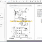
17.1 Lighting Schematic—120V
17.2 Components
17.3 Lighting Schematic—120/240V
17.4 Components
17.5 Generator Capacitor Excitation Schematic
17.6 Generator Capacitor Excitation Schematic
17.7 Engine Wiring
17.8 Components
17.9 Power Winch Schematic
17.10 Trailer Wiring
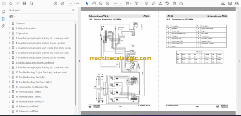
18 Schematics—LTN 6L
18.1 Lighting Schematic—120V
18.2 Components—120V
18.3 Lighting Schematic—120V/240V
18.4 Components—120V/240V
18.5 Engine Wiring Rev > 133
18.6 Components Rev > 133
18.7 Control Panel Wiring Rev > 133
18.8 Components Rev > 133
18.9 Engine Wiring Rev < 134
18.10 Components Rev < 134
18.11 Control Panel Wiring Rev < 134
18.12 Components Rev < 134
18.13 Power Winch Schematic
18.14 Generator Capacitor Excitation Schematic—120V
18.15 Generator Capacitor Excitation Schematic—120V/240V
18.16 Trailer Wiring
19 Schematics—LTN 6K / LTN 8K
19.1 Lighting Schematic—LTN 6K
19.2 Components—LTN 6K
19.3 Lighting Schematic—LTN 8K
19.4 Components—LTN 8K
19.5 Engine Wiring
19.6 Components
19.7 Power Winch Schematic
19.8 Generator Capacitor Excitation Schematic
19.9 Trailer Wiring

