Format: PDF (Printable Document)
File Language: English
File Pages: 96
File Size: 2.32 MB (Speed Download Link)
Brand: Wacker Neuson
Model: RT560, RT820 Trench Roller
Type of Document: Repair Manual
$ 45
UNIT 1 – SAFETY
1.1 General Precautions …………………………………………………………………………….. 1-1
1.2 Operating Safety …………………………………………………………………………………. 1-2
1.3 Engine Safety ……………………………………………………………………………………… 1-2
1.4 Service & Repair Safety ……………………………………………………………………….. 1-3
1.5 Lifting Machine ……………………………………………………………………………………. 1-3
UNIT 2 – GENERAL
2.1 Engine Specifications …………………………………………………………………………… 2-1
2.2 Roller Specifications …………………………………………………………………………….. 2-2
2.3 Lubrication Specifications ……………………………………………………………………… 2-2
2.4 Hydraulic Pressures …………………………………………………………………………….. 2-2
2.5 Operating Systems ……………………………………………………………………………… 2-3
2.6 Reference Numbers ( ) ………………………………………………………………………… 2-3
2.7 Replacement Parts ………………………………………………………………………………. 2-3
2.8 Controls & Service Locations ………………………………………………………………… 2-4
2.9 General Operation ……………………………………………………………………………….. 2-6
2.10 Exciter Operation …………………………………………………………………………………. 2-7
2.11 Engine Speed & Machine Performance …………………………………………………… 2-8
UNIT 3 – HYDRAULIC SYSTEM
3.1 Hydraulic System Cleanliness ……………………………………………………………….. 3-1
3.2 Hydraulic Oil Requirements …………………………………………………………………… 3-1
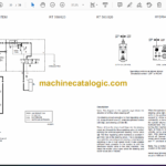
3.3 Hydraulic Flow Diagram………………………………………………………………………… 3-2
3.4 Hydraulic System ………………………………………………………………………………… 3-3
3.5 Control Valve Block ……………………………………………………………………………… 3-4
3.6 Hydraulic Schematic …………………………………………………………………………….. 3-5
3.7 High Speed Travel Circuit ……………………………………………………………………… 3-6
3.8 Low Speed Travel Circuit ……………………………………………………………………… 3-8
3.9 Exciter Circuit ……………………………………………………………………………………. 3-10
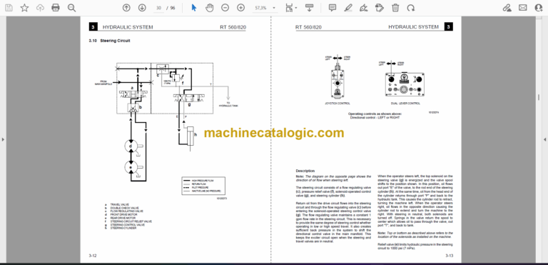
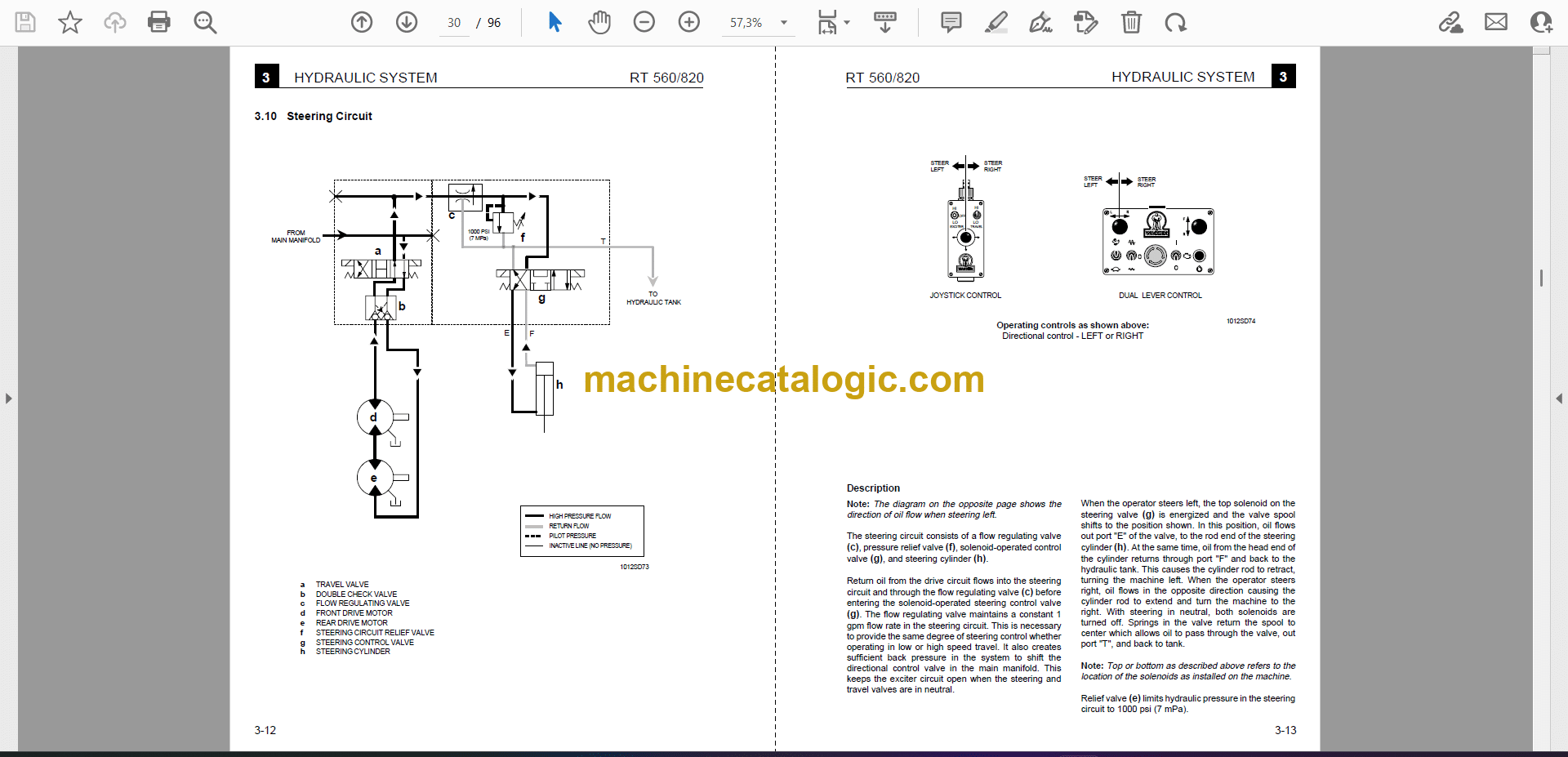
3.10 Steering Circuit ………………………………………………………………………………….. 3-12
3.11 Checking Hydraulic Pressures……………………………………………………………… 3-14
3.12 Checking Drive Circuit ………………………………………………………………………… 3-14
3.13 Checking Vibration Circuit …………………………………………………………………… 3-15
3.14 Checking Steering Circuit ……………………………………………………………………. 3-16
3.15 Testing Drive & Exciter Circuit Relief Valves ………………………………………….. 3-16
3.16 System Pressures ……………………………………………………………………………… 3-16
3.17 Hydraulic Hose Routing and Location …………………………………………………… 3-18
UNIT 4 – DRUM
4.1 Introduction …………………………………………………………………………………………. 4-1
4.2 Changing Oil ……………………………………………………………………………………….. 4-1
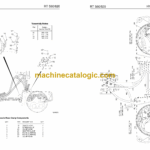
4.3 Drum Assembly – Exploded View …………………………………………………………… 4-2
4.4 Drums ………………………………………………………………………………………………… 4-3
4.5 Drum Support Cover ……………………………………………………………………………. 4-4
4.6 Drive Bearings & Seals…………………………………………………………………………. 4-5
4.7 Drivecase …………………………………………………………………………………………… 4-6
4.8 Drivecase – Exploded View ……………………………………………………………………. 4-7
4.9 Brake (S/N 7100 00000 & Above) ………………………………………………………….. 4-8
4.10 Servicing Brake …………………………………………………………………………………… 4-9
4.11 Drive Motor ……………………………………………………………………………………….. 4-10
4.12 Drivecase Components ………………………………………………………………………. 4-11
UNIT 5 – EXCITER ASSEMBLY
5.1 Introduction …………………………………………………………………………………………. 5-1
5.2 Oil Requirements …………………………………………………………………………………. 5-1
5.3 Exciter Assembly – Exploded view………………………………………………………….. 5-2
5.4 Exciter Cross Section …………………………………………………………………………… 5-4
5.5 Removing and Servicing Exciter Assembly ……………………………………………… 5-5
5.6 Exciter Motor, Coupling & Pinion Gear ……………………………………………………. 5-8
5.7 Exciter Motor …………………………………………………………………………………….. 5-10
UNIT 6 – FRAME
6.1 Shockmount Installation – Exploded View………………………………………………… 6-1
6.2 Replacing Shockmounts ……………………………………………………………………….. 6-2
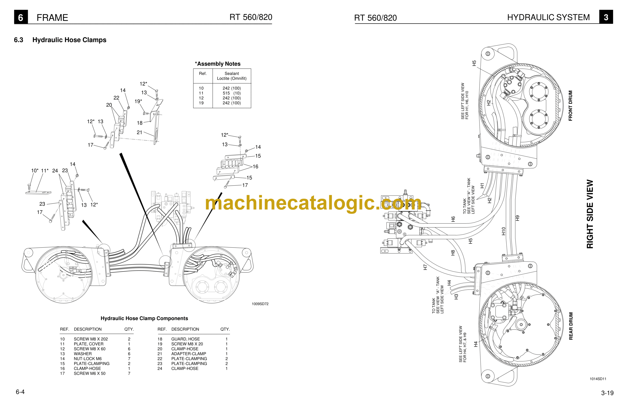
6.3 Hydraulic Hose Clamps ………………………………………………………………………… 6-4
6.4 Drum Supports ……………………………………………………………………………………. 6-5
6.5 Articulated Joint & Steering Cylinder – Exploded View ………………………………. 6-7
6.6 Articulated Joint …………………………………………………………………………………… 6-8
6.7 Steering Cylinder ……………………………………………………………………………….. 6-10
UNIT 7 – POWER TAKE-OFF
7.1 Drive Pump & Coupling – Exploded View ………………………………………………… 7-2
7.2 Pump & Coupling Installation ………………………………………………………………… 7-3
7.3 General Description ……………………………………………………………………………… 7-4
7.4 Engine ……………………………………………………………………………………………….. 7-4
UNIT 8 – ELECTRICAL SYSTEM
8.1 Introduction …………………………………………………………………………………………. 8-1
8.2 Troubleshooting …………………………………………………………………………………… 8-1
8.3 Cord Operated System (S/N 6800 00000 & Below) ………………………………….. 8-2
8.4 Infra-red Operated System (S/N 6800 00000 & Below)……………………………… 8-3
8.5 Infra-red & Cable Operated System (S/N 7100 00000 & Above) ………………… 8-4
Wiring Schematics – S/N 6800 00000 & Below
8.6 Schematic – Cable Operated Control Box ………………………………………………… 8-5
8.7 Schematic – Infra-red Transmitter …………………………………………………………… 8-6
8.8 Schematic – Cord Operated System ……………………………………………………….. 8-7
8.9 Schematic – Infra-red & Cord Operated System ……………………………………….. 8-8
Wiring Schematics – S/N 7100 00000 & Above
8.10 Schematic – Cord Operated Control Box …………………………………………………. 8-9
8.11 Schematic – Infra-red Transmitter …………………………………………………………. 8-10
8.12 Schematic – Machine Wiring ………………………………………………………………… 8-11
8.13 Schematic – Engine Wiring ………………………………………………………………….. 8-12

