Format: PDF (Printable Document)
File Language: English
File Pages: 520
File Size: 95.88 MB (Speed Download Link)
Brand: Wacker Neuson
Model: TH522 Telehandler
Type of Document: Service Manual
$ 45
Service manual Telehandlers TH522
Table of contents
E Introduction
E.1 Notice on this service manual
E.2 Tightening torques
E.3 Safety instructions
B Operation
B.1 Overview of control elements
B.2 Indicator lights and warning lights (overview)
B.3 Steering system
B.4 Accelerator actuation
B.5 Brake
B.6 Machine travel operation
B.7 Differential lock (option)
B.8 Lights/signaling system
B.9 Wiper/washer system
B.10 Heating, ventilation and air conditioning system
B.11 Working hydraulics
B.12 Attachments
B.13 Work operation
B.14 Emergency lowering
B.15 Options
1 Maintenance
1.1 Information on maintenance
1.2 Maintenance overview
1.3 Fluids and lubricants
1.4 Maintenance accesses
1.5 Cleaning and maintenance
1.6 Lubrication work
1.7 Fuel system
1.8 Engine lubrication system
1.9 Cooling system
1.10 Air filter
1.11 V-belt/toothed belt
1.12 Hydraulic system
1.13 Electrical system
1.14 Heating, ventilation and air conditioning system (option)
1.15 Washer system
1.16 Axles/travel drive
1.17 Braking system
1.18 Tires
1.19 Maintenance and servicing work on attachments
1.20 Maintenance of options
1.21 Exhaust gas treatment
2.22 Perkins engine 404F-E22TA (50 kW)
2.23 Alternator
2.24 Starter M001
2.25 Fuel tank
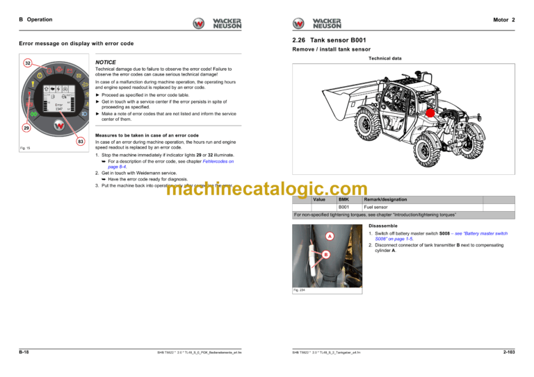
2.26 Tank sensor B001
3 Cooling
3.1 Coolant reservoir
4 Traveling drive
4.1 Cardan shaft
4.2 Servomotor M17/M18
4.3 Type label – transfer gearbox
4.4 Tightening torques and screw locking
4.5 Drain, filler and check plugs
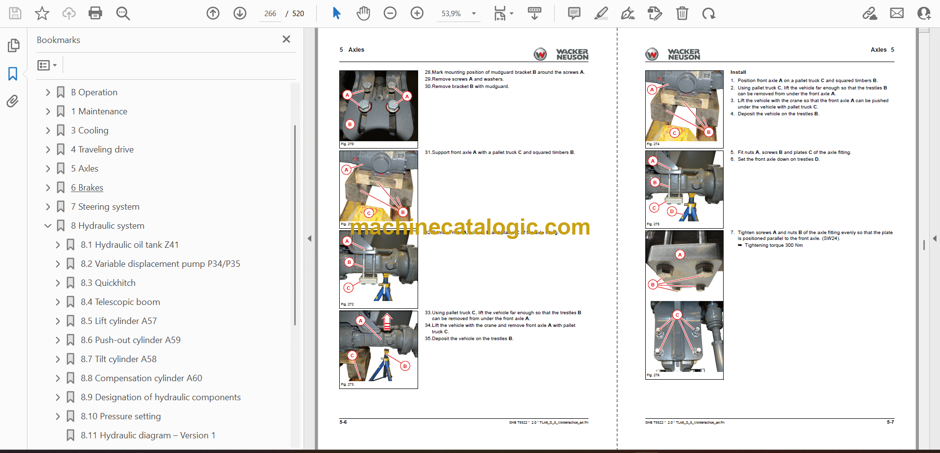
5 Axles
5.1 Front axle
5.2 Rear axle
5.3 Type label – front/rear axle
5.4 Tightening torques and screw locking
5.5 Drain, filler and check plugs
6 Brakes
6.1 Replacing brake linings
7 Steering system
7.1 Steering orbitrol S8
7.2 Steering mode valve V64
8 Hydraulic system
8.1 Hydraulic oil tank Z41
8.2 Variable displacement pump P34/P35
8.3 Quickhitch
8.4 Telescopic boom
8.5 Lift cylinder A57
8.6 Push-out cylinder A59
8.7 Tilt cylinder A58
8.8 Compensation cylinder A60
8.9 Designation of hydraulic components
8.10 Pressure setting
8.11 Hydraulic diagram – Version 1
8.12 Hydraulic diagram – Version 2
8.13 Hydraulic diagram – Version 3
8.14 Hydraulic diagram – Version 4
8.15 Hydraulic diagram – Version 5
9 Electrics
9.1 Fuse assignment
9.2 Relays
9.3 Safe load indicator P006
9.4 Limit switches S116/S142
9.5 Faults on the drive electronics
9.6 Fault table (SPN codes)
9.7 Functional groups
9.8 Component list
9.9 Electrical diagrams
9.10 Plug – Pin assignment 404F-E22TA CRDi
9.11 Plug – Pin assignment 404D-22
12 Trim
12.1 Engine cover
12.2 Underride protection
12.3 Rear covers
12.4 Cabin covers
14 Cabin
14.1 Operator seat
14.2 Cabin
14.3 Air conditioning cooler
14.4 Air conditioning system compressor Y031
17 Automatic coupling
17.1 Ball coupling
17.2 Automatic/rotating trailer coupling
17.3 Self-securing coupling
20 Switches
20.1 Overview of switch assignment
Inde

