Format: PDF (Printable Document)
File Language: English
File Pages: 322
File Size: 54.97 MB (Speed Download Link)
Brand: Wacker Neuson
Model: WL52 Wheel Loader
Type of Document: Service Manual
$ 45
Contents
E Introduction
E.1 Notice on this service manual
E.2 Technical data
E.3 Tightening torques
E.4 Safety instructions
E.5 Special tools
B.1 Overview of control elements
B.2 Indicator lights and warning lights (overview)
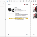
1 Maintenance
1.1 Information on maintenance
1.2 Maintenance overview
1.3 Lubrication plan
1.4 Fluids and lubricants
1.5 Maintenance accesses
1.6 Cleaning and maintenance
1.7 Lubrication work
1.8 Fuel system
1.9 Engine lubrication system
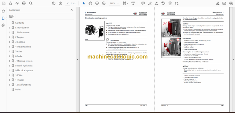
1.10 Cooling system
1.11 Air filter
1.12 V-belt/toothed belt
1.13 Hydraulic system
1.14 Electrical system
1.15 Heating, ventilation and air conditioning system (option)
1.16 Washer system
1.17 Axles/traveling drive
1.18 Braking system
1.19 Tires
1.20 Maintenance and servicing work on attachments
1.21 Maintenance of options
1.22 Exhaust gas treatment
2 Engine
2.1 Complete component
2.2 V-belt
2.3 Alternator
2.4 Removing/installing the starter
2.5 Removing/installing the air filter
2.6 Removing/installing the fuel tank
3 Cooling
3.1 Removing/installing the coolant reservoir
3.2 Removing/installing the radiator
3.3 Removing/installing fan blades
4 Traveling drive
4.1 Traveling drive hose routing
4.2 Variable displacement pump
4.3 Variable displacement motor
4.4 Hydraulic oil reservoir
4.5 Removing/installing the cardan shaft
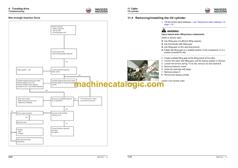
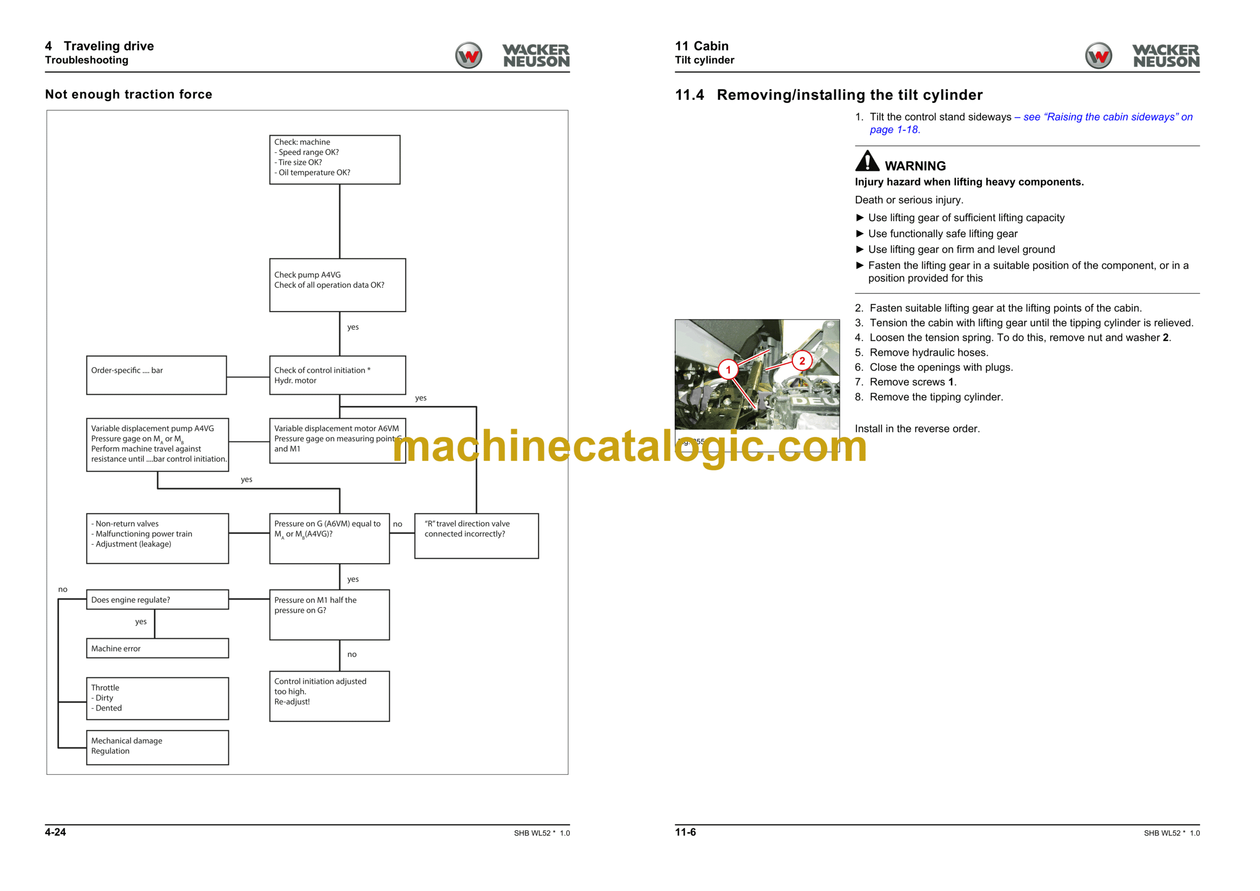
4.6 Troubleshooting
5 Axles
5.1 Front axle
5.2 Rear axle
5.3 Type label – front/rear axle
6 Brake
6.1 Removing/installing the brake pedal
6.2 Removing/installing the parking brake
6.3 Removing/installing the parking brake Bowden cable
6.4 Master brake cylinder
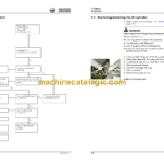
7 Steering system
7.1 Hose routing
7.2 Removing/installing the steering wheel
7.3 Removing/installing the steering column
7.4 Removing/installing steering cylinder A81
7.5 Steering orbitrol S1
8 Work hydraulics
8.1 Overview
8.2 Hose installation
8.3 Gear pump P45
8.4 Removing/installing lock cylinder A4
8.5 Removing/installing the lock pin
8.6 Removing/installing the tilt cylinder
8.7 Removing/installing the loader unit
8.8 Removing/installing the lift cylinder
8.9 Removing/installing the reversing lever
8.10 Removing/installing solenoid valve V30
8.11 Removing/installing pressure relief valve V60
8.12 Removing/installing the quickhitch
8.13 Removing/installing the control valve
8.14 Designation of hydraulic components
8.15 Hydraulics diagram – HDS21/4 with HDS21/1 or 6/2 multiple way valve
8.16 Hydraulics diagram – HDS21/4 with HDS21/2
8.17 Hydraulics diagram – HDS21/3 with HDS21/1 or 6/2-multiple way valve
8.18 Hydraulics diagram – HDS21/3 with HDS21/2
8.19 Hydraulics diagram – HDS21/4 High Flow
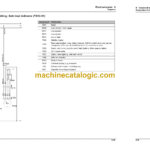
9 Electrical system
9.1 Fuses
9.2 Fuse assignment
9.3 Removing/installing the machine control unit
9.4 Joystick
9.5 Malfunctions of the machine electronics
9.6 Electrical diagram – Power supply (FG01-01)
9.7 Electrical diagram – ECU TTC77; Joystick lighting (FG01-02)
9.8 Electrical diagram – Deutz engine (FG02-01)
9.9 Electrical diagram – Deutz engine (FG02-02)
9.10 Electrical diagram – Deutz engine (FG02-03)
9.11 Electrical diagram – Bauser LED instrument (FG03-01)
9.12 Electrical diagram – Travel function (FG04-01)
9.13 Electrical diagram – StVZO (German road traffic regulations) lighting (FG05-01)
9.14 Electrical diagram – StVZO lighting (FG05-02)
9.15 Electrical diagram – Indicator system; Horn (FG06-01)
9.16 Electrical diagram – Window wiper / wash system (FG07-01)
9.17 Electrical diagram – Working lights; Rotating beacon (FG08-01)
9.18 Electrical diagram – Electrical connection; Tool lock; Continuous operation of 3rd control circuit (FG09-01)
9.19 Electrical diagram – Hydraulic system (FG10-01)
9.20 Electrical diagram – Hydraulic system (FG10-02)
9.21 Electrical diagram – Hydraulic system (FG10-03)
9.22 Electrical diagram – Air conditioning; Seat (FG11-01)
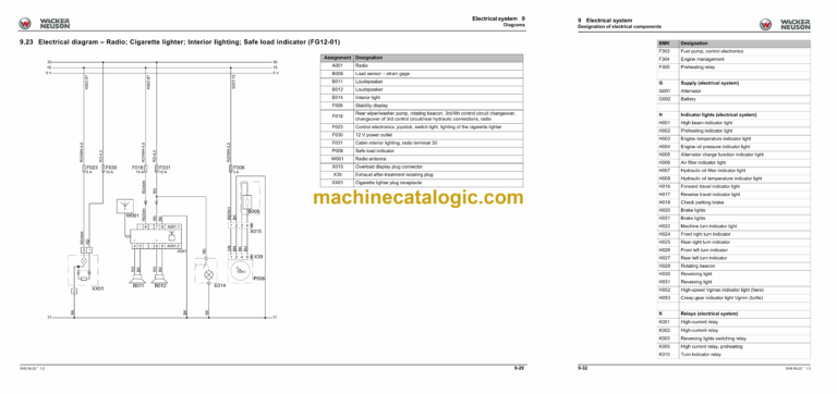
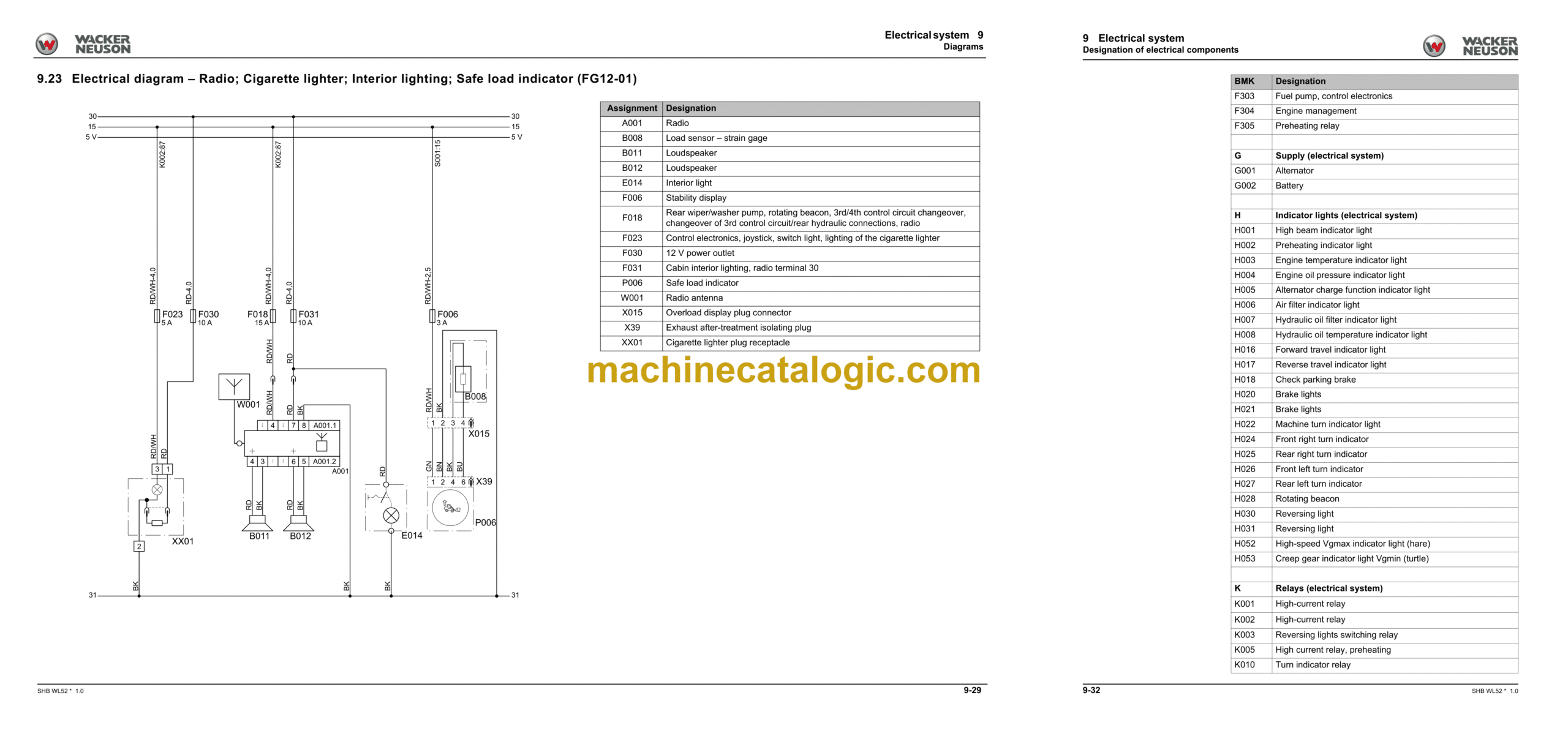
9.23 Electrical diagram – Radio; Cigarette lighter; Interior lighting; Safe load indicator (FG12-01)
9.24 Designation of electrical components
10 Trim
10.1 Removing/installing the engine cover
10.2 Removing/installing the bottom plate
10.3 Removing/installing the trailer power outlet
10.4 Removing/installing the trailer coupling/chassis cover
10.5 Removing/installing the counterweight
11 Cabin
11.1 Removing/installing the operator seat
11.2 Removing/installing the indicating instrument
11.3 Removing/installing the starter
11.4 Removing/installing the tilt cylinder
11.5 Removing/installing the wiper motor
11.6 Heating
11.7 Removing/installing the cabin
12 Malfunctions
12.1 Towing a machine
12.2
