Format: PDF (Printable Document)
File Language: English
File Pages: 120
File Size: 11.66 MB (Speed Download Link)
Brand: Kohler
Model: 13.5CCOZ, 11CCFOZ, 14CCOZ, 11.5CCFOZ, 18.5CCOZ, 15CCFOZ, 18CCFOZ, 20CCOZ, 17.5CCFOZ, 21CCOZ, 16.5CCFOZ, 24CCOZ, 20CCFOZ Marine
Book No: tp5630
Type of Document: Service Manual
$ 40
These Kohler marine gensets usually sit in tight engine rooms, running hotel loads and electronics while the main engines are off. This service manual is what I’d keep on hand to trace electrical or fuel problems and confirm what’s actually failed before I order parts. For example, if the unit cranks but won’t pick up a stable frequency, I’d use this book to walk through the checks on sensors, governor linkage, and wiring instead of guessing at the control board.
Applications & Use Cases
FAQ
Q: Can I use this manual on a tablet in the engine room?
A: Yes, it works well digitally; you can zoom in on diagrams and keep your hands free while testing.
Q: Is it worth printing sections of this manual?
A: Many techs print the pages for a specific job so they can mark notes and keep them next to the unit.
Safety Note
Always lock out power sources and let the generator cool before opening covers or disconnecting components.
SUBJECT PAGE
Safety Precautions and Instructions ………… i
Glossary of Abbreviations ……………….. vi
Reference Material
…
…………………….. VIII
Service Assistance ……………………… ix
Section 1. Introduction …………………. l-l
Specifications ………………………….. l-l
Generator ……………………………. l-l
Engine ……………………………… l-l
Accessories ………………………….. l-l
Service Views …………………………. l-4
Section 2. Operation …………………… 2-l
Prestart Checks ………………………… 2-l
Controller …………………………….. 2-l
Starting ………………………………. 2-2
Preheat Feature (Optional)
13.5/l 4/l 8.5/2OCCOZ and
11/11.5/15/17.5 CCFOZ Models Only …….. 2-2
Stopping ………………………………. 2-2
Circuit Protection ……………………….. 2-3
Engine Safety Shutdown Switches ………….. 2-3
Remote Panels (Optional) ………………… 2-4
Remote Start Panel ……………………. 2-4
Remote Start and Twb-Meter Panel ……….. 2-5
Remote Stat-t and Four-Meter Panel ……….. 2-6
Section 3. Scheduled Maintenance ……….. &I
General ………………………………. 3-1
Service Schedule ………………………. 3-2
Lubrication System ……………………… 3-4
Specifications ………………………… 3-4
OilCheck.. ………………………….. 3-4
Oil Change …………………………… 3-4
Oil Filter Change ………………………. 3-5
Fuel System …………………………… 3-6
Specifications ………………………… 3-6
Fuel Filter ……………………………. 3-6
Bleeding …………………………….. 3-6
Air Intake Silencer Cleaner ……………….. 3-7
Turbocharger (13.5/l 8.5/21 CCOZ
and 11/15/16.5/18CCFOZ) ………………. 3-8
Servicing Mixing Elbow ………………….. 3-9
Governor ……………………………… 3-9
Valve Adjustment. ………………………. 3-9
Cylinder Head Retightening ………………. 3-11
Cooling System ……………………….. 3-11
Closed/Heat Exchanger ……………….. 3-l 1
Siphon Break …………………………. 3-12
SUBJECT PAGE
Belt Tension ………………………….. 3-l 4
Sea Water Pump Belt …………………. 3-14
Battery Charging Alternator Belt …………. 3-l 4
Generator Service ……………………… 3-l 5
Wattage Requirements ………………….. 3-l 5
Storage Procedure …………………….. 3-l 5
Section 4. General Troubleshooting ………. 4-l
Section 5. Controller Troubleshooting …….. 5-l
Sequence of Operation (E-239563
Circuit Board) …………………………. 5-l
Starting.. ……………………………. 5-l
Running …………………………….. 5-l
Stopping …………………………….. 5-2
Engine Safety Shutdown Switches. …………. 5-3
Low Oil Pressure (LOP)
Shutdown Switch …………………….. 5-3
High Water Temperature (HWT) and
High Exhaust Temperature (HET)
Shutdown Switch …………………….. 5-3
Overspeed Safety Shutdown (SDR) ………… 5-3
Section 6. Generator/Controller
Troubleshooting ………………………. 6-l
Controller Circuit Board ………………….. 6-l
Section 7. Component Testing
and Adjustment ………………………. 7-l
Separate Excitation ……………………… 7-l
Voltage Regulator Test-Powerboost” V …….. 7-3
Test Procedure ……………………….. 7-4
Voltage Regulator Adjustment ……………. 7-5
Adjustment Procedure ………………….. 7-6
Exciter Field …………………………… 7-6
Exciter Armature ……………………….. 7-8
Rectifier Module. ……………………….. 7-9
Generator Main Field (Rotor) ……………… 7-9
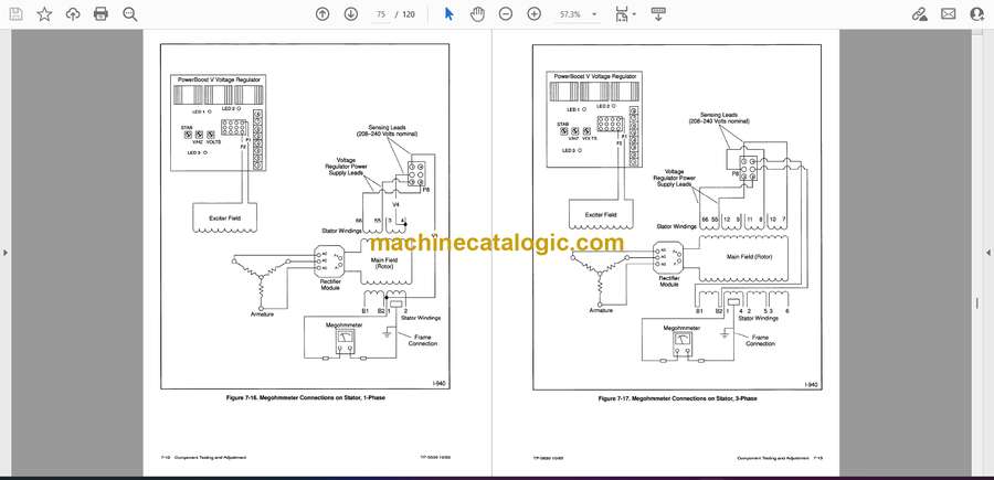
Stator ……………………………… 7-10
Controller Circuit Board …………………. 7-l 4
Engine/Generator Components …………… 7-l 6
Fuel Solenoid ……………………….. 7-l 9
Fuel Pump ………………………….. 7-20
Section 8. Disassembly/Reassembly ……… 8-l
Section 9. Wiring Diagrams ……………… 9-l
Section IO. Specifications Chart ………… IO-I
Generator Models ……………………… 1 O-l
Engine Models ………………………… 1 O-5
Installation …………………………… 1 O-9
Common Hardware Application
Guidelines, Specification G-585 …………. 1 O-l 1
Common Hardware Application (G-585) ……. 1 O-l 2
Common Hardware Identification …………. 1 O-l 3
General Torque Specifications …………… 1 O-l 5


