Format: PDF (Printable Document)
File Language: English
File Pages: 134
File Size: 10.16 MB (Speed Download Link)
Brand: Kohler
Model: ZCB, ZCM, ZCS KBL, KCL Automatic Transfer Switches
Book No: tp5668
Type of Document: Service and Parts Manual
$ 40
These Kohler automatic transfer switches sit between your utility feed and generator, usually in plant rooms, data centers, or commercial buildings, and their only job is to move the load cleanly when the power situation changes. This service and parts manual helps you match every relay, lug, coil, and mechanism in a ZCB, ZCM, or ZCS KBL/KCL switch to the correct part number before you order. When you’re chasing an intermittent transfer issue or replacing a burnt mechanical linkage after a fault, this is what you use to identify exactly which assembly you’ve got in front of you so you don’t pull the panel twice.
Applications & Use Cases
FAQ
Q: Can I zoom in on diagrams on a tablet at the switchgear line-up?
A: Yes, the manual works well as a digital reference so you can zoom in on part callouts right at the jobsite.
Q: Is this worth printing, or should I keep it electronic only?
A: Many techs keep a printed copy in the service truck for quick part cross-checks and use the electronic version for detailed zooming and sharing with the parts desk.
Safety Note
Always isolate and verify all power sources are de-energized before opening or handling any automatic transfer switch components.
Safety Precautions and Instructions . . . . . . . . . . . . . . . . . . . . . . . . . . . . . . . . . . . . . . . . . . . . . . . . . . . . . . . . 5
Introduction . . . . . . . . . . . . . . . . . . . . . . . . . . . . . . . . . . . . . . . . . . . . . . . . . . . . . . . . . . . . . . . . . . . . . . . . . . . . . . . 9
Related Materials . . . . . . . . . . . . . . . . . . . . . . . . . . . . . . . . . . . . . . . . . . . . . . . . . . . . . . . . . . . 9
Service Assistance . . . . . . . . . . . . . . . . . . . . . . . . . . . . . . . . . . . . . . . . . . . . . . . . . . . . . . . . . . . . . . . . . . . . . . . . 10
Section 1 Specifications . . . . . . . . . . . . . . . . . . . . . . . . . . . . . . . . . . . . . . . . . . . . . . . . . . . . . . . . . . . . . . . . . . . 11
1.1 Automatic Transfer Switch Purpose . . . . . . . . . . . . . . . . . . . . . . . . . . . . . . . . . . . . . . 11
1.2 Transfer Switch Components . . . . . . . . . . . . . . . . . . . . . . . . . . . . . . . . . . . . . . . . . . . 11
1.3 Bypass/Isolation Switch Purpose . . . . . . . . . . . . . . . . . . . . . . . . . . . . . . . . . . . . . . . . 11
1.4 Bypass/Isolation Switch Components . . . . . . . . . . . . . . . . . . . . . . . . . . . . . . . . . . . . 12
1.5 Ratings . . . . . . . . . . . . . . . . . . . . . . . . . . . . . . . . . . . . . . . . . . . . . . . . . . . . . . . . . . . . . . 13
1.6 Interpreting Transfer Switch Part Number . . . . . . . . . . . . . . . . . . . . . . . . . . . . . . . . . 14
1.7 ZCS Specifications . . . . . . . . . . . . . . . . . . . . . . . . . . . . . . . . . . . . . . . . . . . . . . . . . . . . 16
1.8 ZCB Specifications . . . . . . . . . . . . . . . . . . . . . . . . . . . . . . . . . . . . . . . . . . . . . . . . . . . . 16
1.9 Standard Features . . . . . . . . . . . . . . . . . . . . . . . . . . . . . . . . . . . . . . . . . . . . . . . . . . . . 16
Section 2 Operation . . . . . . . . . . . . . . . . . . . . . . . . . . . . . . . . . . . . . . . . . . . . . . . . . . . . . . . . . . . . . . . . . . . . . . . 17
2.1 Operation Sequence . . . . . . . . . . . . . . . . . . . . . . . . . . . . . . . . . . . . . . . . . . . . . . . . . . . 17
2.1.1 Normal Source Failure . . . . . . . . . . . . . . . . . . . . . . . . . . . . . . . . . . . . . . . . . 17
2.1.2 Normal Source Restoration . . . . . . . . . . . . . . . . . . . . . . . . . . . . . . . . . . . . . 17
2.2 Control Switches and Indicators . . . . . . . . . . . . . . . . . . . . . . . . . . . . . . . . . . . . . . . . . 17
2.3 Manual Operation . . . . . . . . . . . . . . . . . . . . . . . . . . . . . . . . . . . . . . . . . . . . . . . . . . . . . 18
2.4 ZCB Operation, Switches, and Indicators . . . . . . . . . . . . . . . . . . . . . . . . . . . . . . . . . 18
2.4.1 Bypass/Isolation Cabinet Lights . . . . . . . . . . . . . . . . . . . . . . . . . . . . . . . . . 19
2.4.2 Bypass/Isolation Switch Components . . . . . . . . . . . . . . . . . . . . . . . . . . . . 19
2.5 Time Delay Off . . . . . . . . . . . . . . . . . . . . . . . . . . . . . . . . . . . . . . . . . . . . . . . . . . . . . . . . 20
2.6 Bypass/Isolation Switch Operation . . . . . . . . . . . . . . . . . . . . . . . . . . . . . . . . . . . . . . . 21
2.7 ATS Removal and Reconnection . . . . . . . . . . . . . . . . . . . . . . . . . . . . . . . . . . . . . . . . 24
2.7.1 Removing ATS in 150- to 400-Amp Switches . . . . . . . . . . . . . . . . . . . . . . 24
2.7.2 Reconnecting ATS in 150- to 400-Amp Switches . . . . . . . . . . . . . . . . . . . 24
2.7.3 Removing ATS in 600- to 1200-Amp Switches . . . . . . . . . . . . . . . . . . . . . 25
2.7.4 Reconnecting ATS in 600- to 1200-Amp Switches . . . . . . . . . . . . . . . . . 25
2.7.5 Removing ATS in 1600- to 3000-Amp Switches . . . . . . . . . . . . . . . . . . . . 26
2.7.6 Reconnecting ATS in 1600- to 3000-Amp Switches . . . . . . . . . . . . . . . . 26
Section 3 General Maintenance . . . . . . . . . . . . . . . . . . . . . . . . . . . . . . . . . . . . . . . . . . . . . . . . . . . . . . . . . . . . 27
Section 4 Troubleshooting . . . . . . . . . . . . . . . . . . . . . . . . . . . . . . . . . . . . . . . . . . . . . . . . . . . . . . . . . . . . . . . . . 29
4.1 Power Switching Device Troubleshooting . . . . . . . . . . . . . . . . . . . . . . . . . . . . . . . . . 29
4.2 Model KBL and KCL Controller and RT Box Troubleshooting . . . . . . . . . . . . . . . . 30
4.3 Solenoid Tests . . . . . . . . . . . . . . . . . . . . . . . . . . . . . . . . . . . . . . . . . . . . . . . . . . . . . . . . 30
4.4 Rectifier Test . . . . . . . . . . . . . . . . . . . . . . . . . . . . . . . . . . . . . . . . . . . . . . . . . . . . . . . . . 31
Section 5 Accessory Testing and Adjustment . . . . . . . . . . . . . . . . . . . . . . . . . . . . . . . . . . . . . . . . . . . . . . . 33
5.1 Accessories . . . . . . . . . . . . . . . . . . . . . . . . . . . . . . . . . . . . . . . . . . . . . . . . . . . . . . . . . . 33
5.2 Programmed Transition . . . . . . . . . . . . . . . . . . . . . . . . . . . . . . . . . . . . . . . . . . . . . . . . 33
Table of Contents, continued
4 Table of Contents TP-5668 9/07
Section 6 Disassembly/Reassembly . . . . . . . . . . . . . . . . . . . . . . . . . . . . . . . . . . . . . . . . . . . . . . . . . . . . . . . . 35
6.1 Introduction . . . . . . . . . . . . . . . . . . . . . . . . . . . . . . . . . . . . . . . . . . . . . . . . . . . . . . . . . . 35
6.2 Linear Actuator/Solenoid Removal and Replacement . . . . . . . . . . . . . . . . . . . . . . . 35
6.2.1 150–400 Amp Models . . . . . . . . . . . . . . . . . . . . . . . . . . . . . . . . . . . . . . . . . . 35
6.2.2 600–1200 Amp Models . . . . . . . . . . . . . . . . . . . . . . . . . . . . . . . . . . . . . . . . . 36
6.2.3 1600–3000 Amp Models . . . . . . . . . . . . . . . . . . . . . . . . . . . . . . . . . . . . . . . . 37
6.2.4 1200–3000 Amp Programmed Transition Models . . . . . . . . . . . . . . . . . . 39
6.3 Contact Assembly Removal and Replacement . . . . . . . . . . . . . . . . . . . . . . . . . . . . 40
6.3.1 800–1200 Amp Models . . . . . . . . . . . . . . . . . . . . . . . . . . . . . . . . . . . . . . . . . 40
6.3.2 1600–2000 Amp Models . . . . . . . . . . . . . . . . . . . . . . . . . . . . . . . . . . . . . . . 42
6.3.3 3000 Amp Model . . . . . . . . . . . . . . . . . . . . . . . . . . . . . . . . . . . . . . . . . . . . . . 43
6.4 Auxiliary Switch Removal and Replacement . . . . . . . . . . . . . . . . . . . . . . . . . . . . . . 45
Section 7 Diagrams and Drawings . . . . . . . . . . . . . . . . . . . . . . . . . . . . . . . . . . . . . . . . . . . . . . . . . . . . . . . . . . 47
Section 8 Service Parts . . . . . . . . . . . . . . . . . . . . . . . . . . . . . . . . . . . . . . . . . . . . . . . . . . . . . . . . . . . . . . . . . . . . 91
8.1 Introduction . . . . . . . . . . . . . . . . . . . . . . . . . . . . . . . . . . . . . . . . . . . . . . . . . . . . . . . . . . 91
8.2 Using Parts Lists . . . . . . . . . . . . . . . . . . . . . . . . . . . . . . . . . . . . . . . . . . . . . . . . . . . . . . 91
8.2.1 Finding Parts Information . . . . . . . . . . . . . . . . . . . . . . . . . . . . . . . . . . . . . . . 91
8.2.2 Leads . . . . . . . . . . . . . . . . . . . . . . . . . . . . . . . . . . . . . . . . . . . . . . . . . . . . . . . 91
8.3 Automatic Transfer Switch . . . . . . . . . . . . . . . . . . . . . . . . . . . . . . . . . . . . . . . . . . . . . . 92
8.4 Enclosures, ZCS Only . . . . . . . . . . . . . . . . . . . . . . . . . . . . . . . . . . . . . . . . . . . . . . . . . 93
8.5 Decals . . . . . . . . . . . . . . . . . . . . . . . . . . . . . . . . . . . . . . . . . . . . . . . . . . . . . . . . . . . . . . . 94
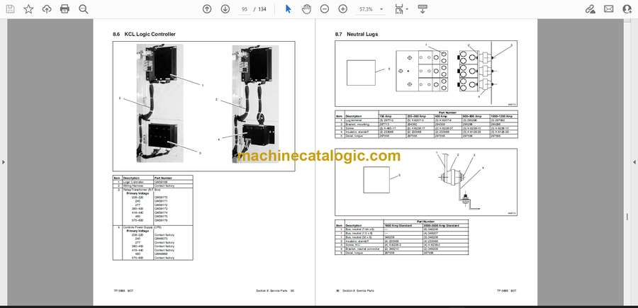
8.6 KCL Logic Controller . . . . . . . . . . . . . . . . . . . . . . . . . . . . . . . . . . . . . . . . . . . . . . . . . . 95
8.7 Neutral Lugs . . . . . . . . . . . . . . . . . . . . . . . . . . . . . . . . . . . . . . . . . . . . . . . . . . . . . . . . . . 96
8.8 Interface Panel Assemblies . . . . . . . . . . . . . . . . . . . . . . . . . . . . . . . . . . . . . . . . . . . . . 97
8.9 Contactor Assemblies, 40–260 Amp Programmed-Transition Models . . . . . . . . . 99
8.10 Contactor Assemblies, 400 Amp Programmed-Transition and
100–400 Amp Closed-Transition Models . . . . . . . . . . . . . . . . . . . . . . . . . . . . . . . . . 100
8.11 Contactor Assemblies, 600–1200 Amp Programmed-Transition and
Closed-Transition Models . . . . . . . . . . . . . . . . . . . . . . . . . . . . . . . . . . . . . . . . . . . . . . 101
8.12 Contactor Assemblies, 1600–3000 Amp Programmed-Transition and
Closed-Transition Models . . . . . . . . . . . . . . . . . . . . . . . . . . . . . . . . . . . . . . . . . . . . . . 102
8.13 Contactor Assemblies, 600–1200 Amp ATS . . . . . . . . . . . . . . . . . . . . . . . . . . . . . . . 103
8.14 Contactor Assemblies, 1600–4000 Amp ATS . . . . . . . . . . . . . . . . . . . . . . . . . . . . . . 104
8.15 Contactor Assemblies, 100–400 Amp ATS/BIS (ZCB) . . . . . . . . . . . . . . . . . . . . . . 106
8.16 Contactor Assemblies, 150–400 Amp ATS/BIS (ZCM) . . . . . . . . . . . . . . . . . . . . . . 108
8.17 Contactor Assemblies, 600–1200 Amp ATS/BIS (ZCB) . . . . . . . . . . . . . . . . . . . . . 112
8.18 Contactor Assemblies, 1600–3000 Amp ATS/BIS (ZCB) . . . . . . . . . . . . . . . . . . . . 114
8.19 Contactor Assemblies, 100–400 Amp ATS/BIS Delay (ZCB) . . . . . . . . . . . . . . . . . 116
8.20 Contactor Assemblies, 100–400 Amp ATS/BIS Delay (ZCM) . . . . . . . . . . . . . . . . 118
8.21 Contactor Assemblies, 600–1200 Amp ATS/BIS Delay (ZCB) . . . . . . . . . . . . . . . . 120
8.22 Contactor Assemblies, 1600–3000 Amp ATS/BIS Delay (ZCB) . . . . . . . . . . . . . . 122
Appendix A Abbreviations . . . . . . . . . . . . . . . . . . . . . . . . . . . . . . . . . . . . . . . . . . . . . . . . . . . . . . . . . . . . . . . . 125
Appendix B Common Hardware Identification . . . . . . . . . . . . . . . . . . . . . . . . . . . . . . . . . . . . . . . . . . . . . . 127
Appendix C Common Hardware List . . . . . . . . . . . . . . . . . . . . . . . . . . . . . . . . . . . . . . . . . . . . . . . . . . . . . . . 128
Appendix D Common Hardware Application Guidelines . . . . . . . . . . . . . . . . . . . . . . . . . . . . . . . . . . . . . 131
Appendix E General Torque Specifications . . . . . . . . . . . . . . . . . . . . . . . . . . . . . . . . . . . . . . . . . . . . . . . . . 132


