Takeuchi TL8R2 Track Loader Workshop Manual (CR6E017) (SN 408000006-)
Out on construction pads, demo sites, or landscaping work, the TL8R2 is usually pushing, lifting, and grading in tight, rough areas. This workshop manual is what I’d pull out when a job stops because something major needs to come off, go back on, or be verified after a repair. If, for example, a customer complains about weak drive on one side, I’d use this book to trace the issue methodically, inspect the drive components, and then reinstall and test everything in the right order so it holds up in the dirt.
Applications & Use Cases
- Plan a full teardown and reassembly of major components so you don’t miss hidden fasteners, shims, or seals.
- Trace hydraulic or drive problems step by step, isolating likely causes instead of just swapping parts.
- Inspect wear items after high-hour operation and decide what must be replaced now versus monitored.
- Verify adjustments and alignments after installing pumps, motors, or linkage so the loader tracks straight and lifts smoothly.
- Perform post-repair checks to confirm everything is bled, routed, and secured before sending the machine back to work.
FAQ
Q: Can I use this manual on a tablet in the field?
A: Yes, it’s practical on a tablet; you can zoom diagrams and keep it beside the machine while you work.
Q: Is it worth printing sections of this manual?
A: Printing the procedures you use often is handy, especially for greasy jobs where you don’t want a device near the work.
Safety Note
Always lock out the machine, support raised components securely, and follow the manual’s cautions before starting any repair.
Takeuchi TL8R2 Track Loader Index:
- REVISION HISTORY
- FOREWORD
- Directional terms: front, rear, left, right
- Machine serial number
- Symbols used in this manual
- Manual structure
- 1. SAFETY
- SAFETY ALERT SYMBOL
- SAFETY PRECAUTIONS
- Observe all safety rules
- Wear safe clothing and protective gear
- Install an extinguisher and a first aid kit
- Lockout/Tagout (LOTO)
- Use the correct tools
- Regularly replace the safety-critical parts
- Explosionproof lighting
- Prohibit access by unauthorized persons
- Prepare the work area
- When the canopy is tilted up
- Keep the machine clean
- Stop the engine before performing maintenance
- Keep clear of the moving fan and belt
- When working under the machine
- When working on the machine
- Securing the working equipment
- Secure the engine hood and guard when they are open
- Place heavy components in a stable position
- Caution when filling with fuel or oil
- Handling of hoses
- Be careful with hot and pressurized components
- Handling of radiator
- Be careful with oils under pressure
- Release the residual pressure from the hydraulic system before performing maintenance
- Be careful with grease under pressure
- Disconnect the battery
- Use caution when handling batteries
- Have a service agent repair welding cracks or other damage
- Checks after maintenance
- Disposing of wastes
- CAUTIONS WHEN WORKING
- Before starting work
- When disassembling or assembling
- When removing/installing the hydraulic unit
- When connecting/disconnecting the hoses or pipes
- Handling of seals
- Pressure adjustment for hydraulic devices
- 2. SERVICE DATA
- DIMENSIONAL DRAWING
- Machine dimensions
- Operating range
- SPECIFICATION TABLES
- Performance
- Dimensions
- Mass
- Engine
- Hydraulic system
- Brake device
- Undercarriage
- Operating device
- Working equipment
- Hydraulic system
- TABLE OF MASSES
- Upper structure
- Lower structure
- Attachments
- LUBRICANT AND FUEL CHART
- PERFORMANCE EVALUATION STANDARD
- Table of standard values
- Table of hydraulic pump assignment
- Performance inspection guideline
- 1. Engine speed
- 2. Hydraulic pressure
- 3. Cylinder speed
- 4. Travel speed
- 5. Crawler shoe 5 rotations
- 6. Straight-ahead travel
- 7. Hydraulic cylinder natural drop
- 8. Natural travel drop
- 9. Bucket front edge
- 10. Service flow rate
- TIGHTENING TORQUE
- Hydraulic hose
- Bite-type pipe fitting for steel pipe
- Joint for piping
- Joint for piping (O-ring seal type)
- Bolts and nuts (JIS strength category 10.9)
- HYDRAULIC CIRCUIT DIAGRAM
- ELECTRICAL CIRCUIT DIAGRAM
- Symbols in electrical circuit diagram
- Wire color symbols
- Wire color table
- Schematic diagram
- Serial No.: 408000006 to 408001908
- Serial No.: 408001909 to 408005142
- Serial No.: 408005143 or later
- HYDRAULIC DEVICE LAYOUT DIAGRAM
- 3. FUNCTION
- HST PUMP
- Contents
- General Discription
- Basic Design
- System Schematic
- Technical Specifications
- System Specifications
- System Parameters
- Hydraulic Fluid Parameters
- Operating Parameters
- System Requirements
- System Parameters
- Hydraulic Fluid Parameters
- Sizing Equations
- System Design Parameters
- Fluid and Filtration
- Filtration Configuration
- Mounting Flange Loads
- Estimating Overhung Load Moment
- Case Drain
- External Shaft Load and Bearing Life
- Hydraulic Unit Life
- Features and Options
- Charge Pump
- Charge Pump Sizing Example:
- Charge Relief Valve
- Overpressure Protection
- Bypass Valve
- Displacement Limiters
- Shaft Option
- Auxiliary Mounting Pads
- Center Coupling
- Non-Feedback, Proportional Hydraulic (NFPH) Control
- Features and Benefits of the NFPH control
- Connectors and Port locations
- NFPH Response Time (maximum to maximum)
- Installation Drawings
- Port Description – Non-Feedback, Proportional Hydraulic (NFPH)
- Dimensions – Non-Feedback, Proportional Hydraulic (NFPH)
- Shaft Option
- Displacement
- By-Pass Valve
- Auxiliary Mounting Pads
- Model Code
- Model Code: A, Y, Z
- Model Code: FD, FX, RD, RX
- Model Code: FE, RE
- Model Code: FT, FH, FJ, FK, RT, RH, RJ, RK
- Model Code: FL, RL, FM, RM
- Model Code: C, F, S
- Model Code: U, G, V
- Model Code: N, P
- GEAR PUMP
- CONTROL VALVE
- Operation when arm-raising operation is activated:
- Operation when arm-lowering operation is activated:
- Operation when the bucket-tilt-backward operation is activated:
- Operation when the arm-float is turned off:
- Operation when the arm-float is activated:
- Load check valve
- Main relief valve
- The relief valve remains turned off:
- The relief valve is activated:
- Port relief valve
- Relief operation:
- Valve suction operation:
- CONTROL VALVE (HIGH FLOW)
- At the neutral position
- During operation
- Load check valve
- Main relief valve
- PILOT VALVE
- When the lever (1) is in the neutral position:
- When the lever (1) is tilted:
- When the lever (1) is kept at a certain position:
- PROPORTIONAL SOLENOID VALVE
- Roles in the hydraulic system
- 1st service
- Active power control
- Operating principle
- Proportional solenoid valve
- SOLENOID VALVE
- Roles in the hydraulic system
- Lever lock
- Variable travel speed
- Operating principle
- SOLENOID VALVE
- Roles in the hydraulic system
- Operating principle
- EMERGENCY VALVE
- RELIEF VALVE
- CYLINDER
- Function of each part
- Rod cover assembly
- Seal system components: Bushing (4), rod packing (6), dust seal (5)
- Piston assembly
- Operating principle
- TRAVEL MOTOR
- 4. DISASSEMBLY AND ASSEMBLY
- SERVICE STANDARD
- Lower structure
- Track roller
- Sprocket
- Idler
- Attachments
- DRIVE EQUIPMENT
- Construction diagram
- Assembly of engine
- Engine assembly
- Radiator assembly
- Assembly of HST pump
- Assembly of gear pump
- Assembly of fuel tank
- Assembly of battery
- Disassembly and assembly
- Removal and installation of the engine
- Removal and installation of the radiator
- Removal and installation of the HST pump
- Bleeding air from the travel main piping and pilot piping
- Removal and installation of the gear pump
- Removal and installation of the fuel tank
- TRAVEL EQUIPMENT
- Construction diagram
- Assembly of track roller
- Assembly of front idler
- Assembly of grease cylinder
- Assembly of travel motor
- Disassembly and assembly
- Removal of the rubber crawler
- Installation of the rubber crawler
- Removal of the track rollers A and C
- Installation of the track rollers A and C
- Removal of the track roller B
- Installation of the track roller B
- Removal and installation of the front idler assembly and grease cylinder assembly
- Removal and installation of the travel motor
- FRAME
- Construction diagram
- Assembly of main unit
- Assembly of floor
- Assembly of operator seat
- Assembly of cover
- Assembly of cover
- Assembly of cab mounting
- Assembly of canopy mounting
- Disassembly and assembly
- Tilting up and tilting down of the cab assembly (canopy assembly)
- Installation and removal of the lift arm stopper
- Removal and installation of the floor assembly parts
- Removal and installation of the side cover L assembly and side cover R assembly
- Removal and installation of the engine hood assembly
- Removal and installation of the rear door assembly
- Removal and installation of the cab assembly (canopy assembly)
- CONTROL EQUIPMENT
- Construction diagram
- Assembly of pilot piping
- Assembly of pilot valve
- Assembly of safety bar
- Disassembly and assembly
- Removal and installation of the left pilot valve assembly and right pilot valve assembly
- WORK EQUIPMENT
- Construction diagram
- Assembly of quick-hitch
- Assembly of lift arm
- Assembly of lift arm piping
- Disassembly and assembly
- Removal and installation of the quick-hitch
- Removal and installation of the bucket cylinder L and bucket cylinder R
- Adjustment of the bucket stopper
- Removal and installation of the lift arm
- Removal and installation of the arm cylinder
- Adjustment of the arm stopper
- HYDRAULIC OIL TANK
- Construction diagram
- Assembly of hydraulic oil tank
- Disassembly and assembly
- Removal and installation of the hydraulic oil tank
- Oil level inspection and replenishment of the hydraulic oil tank
- Method for bleeding air
- HST PUMP
- GEAR PUMP
- Construction
- Disassembly
- Inspection and adjustment
- Checking the parts
- Test operation
- Measuring the discharge volume
- GEAR PUMP (HIGH FLOW)
- Construction
- Disassembly
- Inspection and adjustment
- Checking the parts
- Test operation
- Measuring the discharge volume
- CONTROL VALVE
- Construction
- Disassembly and assembly
- General precautions
- Disassembly
- Inspection and adjustment
- Adjusting the flow ratio
- Adjustment procedure
- CONTROL VALVE (HIGH FLOW)
- Construction
- Disassembly and assembly
- General precautions
- Disassembly
- Assembly
- Inspection and adjustments
- Checking the parts
- Adjusting the main relief valve pressure
- PILOT VALVE
- Construction
- Special tools
- Installation jig A
- Installation jig B
- Disassembly and assembly
- General precautions
- Disassembly
- Assembly
- Inspection and adjustment
- PROPORTIONAL SOLENOID VALVE
- Construction diagram
- Proportional solenoid valve
- Solenoid proportional pressure reducing valve
- Disassembly and assembly
- Service standard
- SOLENOID VALVE
- Construction diagram
- Disassembly and assembly
- Inspection and adjustment
- SOLENOID VALVE
- Construction diagram
- Disassembly and assembly
- Inspection and adjustment
- EMERGENCY VALVE
- Three-view diagram
- Disassembly and assembly
- Disassembling the emergency valve
- Assembling the emergency valve
- CYLINDER
- Construction diagram
- Arm cylinder
- Bucket cylinder L
- Bucket cylinder R
- Quick-hitch cylinder
- Disassembly and assembly
- Tools required for disassembly and assembly
- Disassembly
- Cleaning and storage
- Assembly
- Performance inspection after assembly
- Service standard
- HST PUMP
- WIRE HARNESS
- Electrical wiring assembly: 06642-00155-00
- Body wiring assembly: 06642-00156-07 (Page 1 of 3)
- Body wiring assembly: 06642-00156-07 (Page 2 of 3)
- Body wiring assembly: 06642-00156-07 (Page 3 of 3)
- Wire harness: 06642-00189-06
- Wire harness: 06642-00195-03
- Wire harness: 06642-00196-02
- Wire harness: 06642-00198-02
- Wire harness: 06642-00209-00
- Wire harness: 06642-00248-00
- Engine wiring assembly: 06642-00157-05
- Wire harness: 06542-00077-01
- Wire harness: 06642-00194-03
- Wire harness: 06642-00244-02
- Floor wiring assembly and control valve wiring assembly: 06642-00205-00, 06642-00206-01, 06642-00207-03
- Wire harness: 03343-40191-00
- Wire harness: 06643-00011-00
- Wire harness: 06642-00201-02
- Wire harness: 06642-00251-02
- Attachment wiring assembly: 06642-00160-04
- Wire harness: 06542-00044-00
- Wire harness: 06642-00202-04
- GPS device assembly: 06642-00173-03
- Battery assembly: 06644-00020-04
- Windshield washer assembly: 06689-00007-00
- Radio assembly: 06647-00005-00
- Wire harness: 06647-00006-02
- Reversing camera assembly: 06642-00169-02
- Wire harness: 06542-00098-01
- Cable: 06542-00111-01
- Foot accelerator pedal assembly: 06641-00006-00
- Wire harness: 06642-00185-00
- Canopy wiring diagram
- Wire harness: 06684-00053-01
- Cabin wiring diagram
- Wire harness: 06686-00143-01
- Wire harness: 06686-00144-01
- Wire harness: 06986-00229-00
- Switch assembly: 06686-00190-00 (Canopy specification machine)
- Switch assembly: 06686-00191-00 (Cabin specification machine)
- Air conditioner wiring assembly
- Wire harness: 06642-00199-02
- Quick-hitch wiring assembly
- Wire harness: 06642-00203-01
- Pump wiring assembly: 06652-00009-00
- Wire harness: 06652-00011-01
- Pump wiring assembly: 06652-00010-02
- Wire harness: 06652-00012-01
- MAIN UNIT HYDRAULIC PIPING
- Construction diagram
- Main unit hydraulic piping assembly
- 5. TROUBLESHOOTING
- OVERALL MACHINE
- Engine does not start
- Engine cannot speed up
- No operation is possible (travel, lift arm, bucket, service)
- All systems working (travel, lift arm, bucket, service) but insufficient speed and power
- Lift arm, bucket, and services all do not operate or the operation speed is slow (travel operates normally)
- TRAVELING
- Right and left travel motors do not operate
- Right or left travel speed decelerates and the machine veers to one side
- No variable travel speed
- LIFT ARM
- Lift arm does not operate, or either cannot ascend or descend
- Lift arm can ascend or descend but the speed and force are low
- When the control lever is pulled slowly, the lift arm drops temporarily
- Spontaneous drop of the lift arm is too large
- BUCKET
- Bucket does not operate, or cannot tilt either forward or backward
- Bucket can tilt backward or forward but the speed and force are low
- Spontaneous drop of the bucket is too large
- SERVICE
- Service does not operate, or either Service A or B does not operate
- GEAR PUMP
- PILOT VALVE
- PROPORTIONAL SOLENOID VALVE (ACTIVE POWER CONTROL, 1ST AUXILIARY LINE PIPING)
- SOLENOID VALVE
- SOLENOID VALVE
- 6. OTHER
- MAINTENANCE SOFTWARE MANUAL
- CONTENTS
- 1. OVERVIEW
- 2. CONNECTION METHOD
- 2-1. Parts needed
- 2-2. Installation method
- 2-2-1. Installation of “PLUS+1 Service Tool”
- 2-2-2. Installation of maintenance tool driver
- 2-3. Connection to work machine and startup of maintenance software
- AIR CONDITIONER
- Construction diagram
- Assembly of compressor
- Assembly of condenser
- Assembly of air conditioner unit
- Disassembly and assembly
- Removal and installation of the compressor
- Removal and installation of the fan
- Removal and installation of the condenser
- Removal and installation of the receiver dryer
- Removal and installation of the air conditioner unit
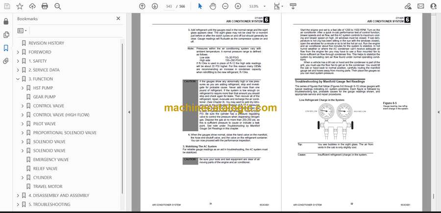
- AIR CONDITIONER SYSTEM
- Overview of System Operation
- Inspection and Maintenance without gauges
- Troubleshooting & Service Procedures
- Electrical wiring diagram
- VEHICLE ERROR CODES
- Diagnostics procedures for malfunctions and failure
- Repair procedures
- How to check the detection ports
- VEHICLE ERROR CODES
- TABLE OF ENGINE ERROR CODES
Takeuchi


