Takeuchi TL11R3 Track Loader Workshop Manual (CAC1E002) (SN 411000006-)
The TL11R3 is a high-production track loader that spends its life in mud, demolition rubble, and tight grading jobs, so when something’s off, you need to trace it quickly and get back to work. This workshop manual is what I’d pull out when I’m doing deeper repairs—pulling a drive motor, chasing a hydraulic leak, or reinstalling a boom cylinder after resealing it. For example, if the loader starts tracking weak on one side, this book walks me through a logical sequence to isolate whether it’s control, hydraulic, or mechanical, then guides the reassembly checks so I know it’ll run straight when it leaves the shop.
Applications & Use Cases
- Plan major component removal so hoses, wiring, and hardware go back exactly where they belong.
- Trace hydraulic issues by following recommended inspection and test sequences instead of guessing.
- Verify undercarriage work—track, sprocket, and roller reinstall—so alignment and tension are correct.
- Inspect and reseal cylinders or valves with proper order of teardown and safe reassembly checks.
- Confirm control and safety function after repairs, before the machine returns to a rough jobsite.
FAQ
Q: Can I keep this manual on a tablet in the field?
A: Yes, it’s practical to use on a tablet or laptop; you can zoom diagrams and search terms while you’re at the machine.
Q: Is it worth printing sections of this manual?
A: Many techs print only the procedures they’re doing that day, so they can mark notes, grease spots don’t ruin a device, and pages can go right in the job folder.
Safety Note
Always lock out, support, and relieve system pressures exactly as described before loosening any component.
Takeuchi TL11R3 Track Loader Index:
- REVISION HISTORY
- FOREWORD
- Directional terms: front, rear, left, right
- Machine serial number
- Symbols used in this manual
- Manual structure
- 1. SAFETY
- SAFETY ALERT SYMBOL
- SAFETY PRECAUTIONS
- Observe all safety rules
- Wear safe clothing and protective gear
- Install an extinguisher and a first aid kit
- Lockout/Tagout (LOTO)
- Use the correct tools
- Regularly replace the safety-critical parts
- Explosionproof lighting
- Prohibit access by unauthorized persons
- Prepare the work area
- When the canopy is tilted up
- Keep the machine clean
- Stop the engine before performing maintenance
- Keep clear of the moving fan and belt
- When working under the machine
- When working on the machine
- Securing the working equipment
- Secure the engine hood and guard when they are open
- Place heavy components in a stable position
- Caution when filling with fuel or oil
- Preventing Fire and Explosion
- Be careful with hot and pressurized components
- Handling of radiator
- Be careful with oils under pressure
- Release the residual pressure from the hydraulic system before performing maintenance
- Be careful with grease under pressure
- Handling of the accumulator
- Disconnect the battery
- Use caution when handling batteries
- Have a service agent repair welding cracks or other damage
- Checks after maintenance
- Disposing of wastes
- Cautions for handling DEF/AdBlue®
- Always maintain 3 points of contact when getting on and off the machine.
- Cautions when starting the engine
- Do not allow anyone other than the operator on the machine.
- If the cab or canopy is damaged
- Beware of fragments when working with a hammer
- Precautions when performing maintenance on the air conditioner
- CAUTIONS WHEN WORKING
- Before starting work
- When disassembling or assembling
- When removing/installing the hydraulic unit
- When connecting/disconnecting the hoses or pipes
- Handling of seals
- Pressure adjustment for hydraulic devices
- 2. SERVICE DATA
- DIMENSIONAL DRAWING
- Machine dimensions
- Operating range
- SPECIFICATION TABLE
- Performance
- Dimensions
- Mass
- Engine
- Hydraulic equipment
- Brake equipment
- Undercarriage
- Control equipment
- Instruments
- Names of parts
- Work equipment
- TABLE OF MASSES
- Upper structure
- Lower structure
- Attachments
- TABLE OF FUEL AND LUBRICANT
- Diesel fuel
- Lubricant
- DEF/AdBlue®
- Applicable standard for DEF/AdBlue®
- Replenishment amount
- PERFORMANCE EVALUATION STANDARD
- Table of standard values
- Table of hydraulic pump assignment
- Performance inspection guideline
- 1. Engine speed
- 2. Hydraulic pressure
- 3. Cylinder speed
- 4. Travel speed
- 5. Crawler shoe 5 rotations
- 6. Straight-ahead travel
- 7. Hydraulic cylinder natural drop
- 8. Natural travel drop
- 9. Bucket front edge
- 10. Service flow rate
- TIGHTENING TORQUE
- Hydraulic hose
- Bite-type pipe fitting for steel pipe
- Joint for piping
- Joint for piping (O-ring seal type)
- Bolts and nuts (JIS strength category 10.9)
- HYDRAULIC CIRCUIT DIAGRAM
- ELECTRICAL CIRCUIT DIAGRAM
- Symbols in electrical circuit diagram
- Wire color symbols
- Wire color table
- Schematic diagram
- WIRE HARNESS
- Electrical wiring assembly
- Cab specification
- Main unit wiring assembly
- Engine wiring assembly
- Floor wiring assembly
- Canopy specification
- Main unit wiring assembly
- Engine wiring assembly
- Floor wiring assembly
- Foot accelerator assembly
- Attachment wiring assembly
- Rear door wiring assembly
- Inertial sensor assembly
- Wire harness
- Wire harness
- Back camera assembly
- Radio assembly
- 270° camera assembly
- Wire harness
- Cable
- Wire harness
- Wire harness
- Wire harness
- Wire harness
- Cable
- Cable
- Condenser assembly
- Cab mounting assembly
- Wire harness
- Wire harness
- Wire harness
- Canopy mounting assembly
- Harness supplied with engine
- HYDRAULIC DEVICE LAYOUT DIAGRAM
- 3. FUNCTION
- HST PUMP
- Contents
- Series 42 warehouse
- General Discription
- Basic Design
- System Schematic
- Technical Specifications
- System Specifications
- System Parameters
- Hydraulic Fluid Parameters
- Operating Parameters
- System Requirements
- System Parameters
- Hydraulic Fluid Parameters
- Sizing Equations
- System Design Parameters
- Fluid and Filtration
- Filtration Configuration
- Mounting Flange Loads
- Estimating Overhung Load Moment
- Case Drain
- External Shaft Load and Bearing Life
- Hydraulic Unit Life
- Features and Options
- Charge Pump
- Charge Pump Sizing Example:
- Charge Relief Valve
- Overpressure Protection
- Bypass Valve
- Displacement Limiters
- Shaft Option
- Auxiliary Mounting Pads
- Center Coupling
- Non-Feedback, Proportional Electric (NFPE) Control
- Installation Drawings
- Port Description – Non-Feedback, Proportional Hydraulic (NFPH)
- Dimensions – Non-Feedback, Proportional Hydraulic (NFPH)
- Shaft Option
- Displacement
- By-Pass Valve
- Auxiliary Mounting Pads
- Model Code
- Model Code: A, Y, Z
- Model Code: FD, FX, RD, RX
- Model Code: FE, RE
- Model Code: FT, FH, FJ, FK, RT, RH, RJ, RK
- Model Code: FL, RL, FM, RM
- Model Code: C, F, S
- Model Code: U, G, V
- Model Code: N, P
- GEAR PUMP
- CONTROL VALVE
- At neutral position
- Other than high flow specification
- High flow specification
- Valve operation during lift arm raising operation
- Valve operation during lift arm lowering operation
- Valve operation during bucket rollback operation
- Valve operation during bucket dumping operation
- Valve operation when the lift arm float is OFF
- Valve operation during lift arm float operation
- Valve operation when the leveling cancellation is OFF
- Valve operation when the leveling cancellation is ON
- 1st service operation (high flow specification)
- 2nd service operation (high flow specification)
- Operation of the main relief valve
- When the working pressure is lower than the set value
- When the working pressure is higher than the set value
- Operation of the overload relief valve
- Operation of the overload relief valve during suction
- PILOT VALVE (OPERATION LEVER)
- SOLENOID VALVE
- Roles in the hydraulic system
- Lever lock
- Variable travel speed
- Operating principle
- SOLENOID VALVE (PARKING BRAKE)
- EMERGENCY VALVE
- RELIEF VALVE
- CYLINDER
- Function of each part
- Rod cover assembly
- Seal system components: Bushing (4), U-ring (5), Wiper ring (6)
- Piston assembly
- Pipe assembly
- Operation
- CYLINDER
- Overview
- Function of each part
- Rod cover assembly
- Seal system components: Bushing (4), rod packing (6), dust seal (5)
- Piston assembly
- Operating principle
- TRAVEL MOTOR
- 4. DISASSEMBLY AND ASSEMBLY
- SERVICE STANDARD
- Track roller B
- Track roller C
- Sprocket
- Front idler
- Pin
- DRIVE EQUIPMENT
- Construction diagram
- Assembly of engine
- Assembly of hydraulic pump
- Assembly of fuel tank
- Assembly of battery
- Disassembly and assembly
- Removal and installation of the engine
- Removal and installation of the radiator
- Removal and installation of the HST pump
- Removal and installation of the gear pump
- Removal and installation of the fuel tank
- Removal and installation of the battery
- TRAVEL EQUIPMENT
- Construction diagram
- Assembly of track roller
- Assembly of front idler
- Assembly of grease cylinder
- Assembly of travel motor
- Disassembly and assembly
- Removal of the rubber crawler
- Installation of the rubber crawler
- Removal of the track roller C
- Installation of the track roller C
- Removal of the track roller B
- Installation of the track roller B
- Removal and installation of the front idler assembly and grease cylinder assembly
- Removal and installation of the travel motor
- FRAME
- Construction diagram
- Assembly of main unit
- Assembly of counterweight
- Assembly of floor
- Assembly of operator seat
- Assembly of cover
- Assembly of cab mounting
- Assembly of canopy mounting
- Disassembly and assembly
- Tilting up and tilting down of the cab assembly (canopy assembly)
- Installation and removal of the lift arm stopper
- Removal and installation of the floor plate
- Removal and installation of the side cover L assembly and side cover R assembly
- Removal and installation of the engine hood assembly
- Removal and installation of the rear door assembly
- Removal and installation of the cab assembly (canopy assembly)
- CONTROL EQUIPMENT
- Construction diagram
- Assembly of remote control unit
- Assembly of foot accelerator
- Assembly of safety bar
- Disassembly and assembly
- Removal and installation of the accumulator
- WORK EQUIPMENT
- Construction diagram
- Assembly of quick-hitch
- Assembly of lift arm
- Assembly of lift arm piping
- Disassembly and assembly
- Greasing
- Removal and installation of the quick-hitch
- Removal and installation of the lift arm
- Adjustment of the bucket stopper
- Adjustment of the arm stopper
- Removal and installation of only each cylinder
- Removal and installation of the bucket cylinder
- Removal and installation of the lift arm cylinder
- HYDRAULIC OIL TANK
- Construction diagram
- Assembly of hydraulic oil tank
- Disassembly and assembly
- Removal and installation of the hydraulic oil tank
- Oil level inspection and replenishment of the hydraulic oil tank
- Method for bleeding air
- HST PUMP
- GEAR PUMP
- Construction
- Exploded diagram
- Internal construction diagram
- Disassembly and assembly
- General precautions
- Disassembly
- Assembly
- GEAR PUMP (HIGH FLOW)
- Construction
- Exploded diagram
- Internal construction diagram
- Disassembly and assembly
- General precautions
- Disassembly
- Assembly
- CONTROL VALVE
- Construction diagram
- Other than high flow specification
- High flow specification
- Disassembly
- Precautions for disassembly
- Tool
- Pullout of the spools
- High flow section
- Lift arm, bucket, 1st service, and 2nd service sections
- Divider/sequence section
- Removal of the check valve and load check valve
- Removal of the check valve and load check valve (part A)
- Removal of the load check valve (part B)
- Removal of the main relief valve
- Removal of the overload relief valve
- Lift arm and bucket sections
- 1st service and 2nd service sections
- Removal of the flow ratio adjusting valve
- Removal of the lift arm float valve and leveling cancel valve
- Removal of the lift arm float valve
- Removal of the leveling cancel valve
- Removal of the solenoid valve
- Removal of the ON-OFF valve
- Removal of the proportional valve
- Removal of other parts
- G3/8 plug
- G1/2 plug
- G1/4 plug
- M27 plug (high flow specification)
- G1 plug (high flow specification)
- Main unit (high flow specification)
- Assembly
- Precautions for assembly
- Precautions for installation of seal parts
- Main unit
- Assembly of the spools
- High flow section
- Lift arm, bucket, 1st service, and 2nd service sections
- Divider/sequence section
- Assembly of the check valve and load check valve
- Assembly of the check valve and load check valve (part A)
- Assembly of the load check valve (part B)
- Installation of the main relief valve
- Installation of the overload relief valve
- Lift arm and bucket sections
- 1st service and 2nd service sections
- Installation of the flow ratio adjusting valve
- Installation of the lift arm float valve and leveling cancel valve
- Installation of the lift arm float valve
- Installation of the leveling cancel valve
- Installation of the solenoid valve
- Installation of the ON-OFF valve
- Installation of the proportional valve
- Installation of other parts
- G3/8 plug
- G1/2 plug
- G1/4 plug
- M27 plug (high flow specification)
- G1 plug (high flow specification)
- SOLENOID VALVE
- Construction diagram
- Disassembly and assembly
- Inspection and adjustment
- SOLENOID VALVE (PARKING BRAKE)
- Construction
- Disassembly and Assembly
- Inspection and adjustment
- EMERGENCY VALVE
- Three-view diagram
- Disassembly and assembly
- Disassembling the emergency valve
- Assembling the emergency valve
- CYLINDER
- Construction diagram
- Disassembly and assembly
- Preparation
- Service standard
- Inspection after assembly
- Tools required for disassembly and assembly
- General tools
- Special tools
- Disassembly
- Assembly
- CYLINDER
- Construction diagram
- Disassembly and assembly
- Tools required for disassembly and assembly
- Disassembly
- Cleaning and storage
- Assembly
- Performance inspection after assembly
- Service standard
- TRAVEL MOTOR
- MAIN UNIT HYDRAULIC PIPING
- Main unit hydraulic piping
- Construction diagram
- Table of connections
- 5. TROUBLESHOOTING
- TROUBLESHOOTING
- Notes on the malfunction diagnosis and repair
- GENERAL
- The engine does not start.
- 1. Did an error code occur?
- 2. Does the starter motor rotate?
- 3. Is there enough fuel?
- 4. Is there an abnormality in the fuel hose?
- 5. Is the fuel filter clogged?
- The engine speed cannot be increased.
- 1. Did an error code occur?
- No operation is possible.
- 1. Did a vehicle error code occur?
- 2. Is the specified amount of hydraulic oil available?
- 3. Is the voltage applied to the solenoid valve (lever lock)?
- 4. Does the spool of the solenoid valve (lever lock) move?
- 5. Is the pilot pressure within the standard value range?
- 6. Is the bucket pressure within the standard value range?
- All operations are possible but the speed is slow.
- 1. Does the engine speed reach the maximum?
- 2. Is the specified amount of hydraulic oil available?
- 3. Is the hydraulic pump making an abnormal noise?
- 4. Is the pilot pressure within the standard value range?
- 5. Is the bucket pressure within the standard value range?
- The cluster screen is not displayed, so authentication is not possible and the engine cannot be started.
- 1. Does the engine start by the following check procedure that uses the RFID key?
- TRAVEL
- The work machine cannot travel.
- 1. Did a vehicle error code occur?
- 2. Are lift arm, bucket, and service operations all possible?
- 3. Do travel inputs occur with the main controller?
- 4. Do travel outputs occur with the main controller?
- 5. Do parking brake outputs occur with the main controller?
- 6. Is the pressure from the solenoid valve (parking brake) normal?
- 7. Is the travel pressure within the standard value range?
- The machine veers to one side with the left or right travel speed slowing down when it travels forward or backward.
- 1. Is the crawler tension normal?
- 2. Is any foreign matter trapped in the crawler?
- 3. Is the sprocket disengaged or loose?
- 4. Do travel outputs occur for both left and right travel with the main controller?
- 5. Is travel pressure for both left and right travel within the standard value range?
- The variable travel speed cannot be changed.
- 1. Do variable travel speed inputs occur with the main controller?
- 2. Do variable travel speed outputs occur with the main controller?
- 3. Is the variable travel speed pressure from the solenoid valve (variable travel speed) normal?
- LIFT ARM
- The lift arm is inoperable.
- 1. Did an error code occur?
- 2. Are travel, bucket, and service operations all possible?
- 3. Do lift arm inputs occur with the main controller?
- 4. Do lift arm outputs occur with the main controller?
- 5. Is the discharge pressure from the control valve (lift arm section) normal?
- The lift arm operation is slow or lacks power.
- 1. Are travel, bucket, and service operations all normal?
- 2. Is the lift arm operation distance with the main controller normal?
- 3. Are lift arm output values with the main controller normal?
- 4. Is the discharge pressure from the control valve (lift arm section) normal?
- When the lift arm control lever is pulled slowly, the lift arm drops temporarily.
- 1. Is the lift arm cylinder leaking internally?
- The amount of lift arm natural drop is large.
- 1. Is oil leaking from the hydraulic piping connected to the head side of the lift arm cylinder?
- 2. Is the lift arm cylinder leaking internally?
- 3. Is there any foreign matter caught in the overload relief valve or float pilot check valve of the control valve? Or are there any scratches on the seat of the control valve?
- 4. Is there any foreign matter caught in the emergency valve? Or are there any scratches on the seat of the emergency valve?
- BUCKET
- The bucket is inoperable.
- 1. Did an error code occur?
- 2. Are travel, lift arm, and service operations all possible?
- 3. Do bucket inputs occur with the main controller?
- 4. Do bucket outputs occur with the main controller?
- 5. Is the discharge pressure from the control valve (bucket section) normal?
- The bucket operation is slow or lacks power.
- 1. Are travel, lift arm, and service operations all normal?
- 2. Is the bucket operation distance with the main controller normal?
- 3. Are bucket output values with the main controller normal?
- 4. Is the discharge pressure from the control valve (bucket section) normal?
- The amount of bucket natural drop is large.
- 1. Is oil leaking from the hydraulic piping connected to the rod side of the bucket cylinder?
- 2. Is the bucket cylinder leaking internally?
- 3. Is there any foreign matter caught in the overload relief valve of the control valve? Or are there any scratches on the seat of the control valve?
- SERVICE
- The attachment connected to the 1st service is inoperable.
- 1. Did an error code occur?
- 2. Are travel, lift arm, and bucket operations all possible?
- 3. Do 1st service inputs occur with the main controller?
- 4. Do 1st service outputs occur with the main controller?
- 5. Is the discharge pressure from the control valve (1st service section) normal?
- The attachment connected to the 2nd service is inoperable.
- 1. Did an error code occur?
- 2. Are travel, lift arm, and bucket operations all possible?
- 3. Do 2nd service inputs occur with the main controller?
- 4. Do 2nd service outputs occur with the main controller?
- 5. Is the discharge pressure from the control valve (2nd service section) normal?
- GEAR PUMP
- CONTROL VALVE
- SOLENOID VALVE
- SOLENOID VALVE (PARKING BRAKE)
- CYLINDER
- 6. OTHER
- MAINTENANCE SOFTWARE MANUAL
- CONTENTS
- 1. OVERVIEW
- 2. CONNECTION METHOD
- 2-1. Parts needed
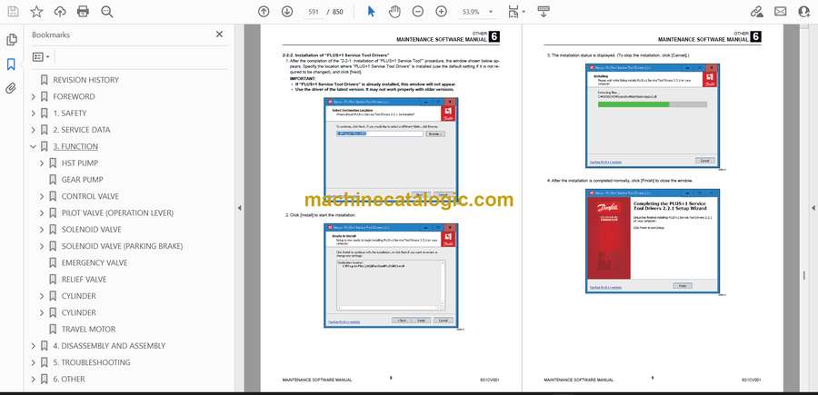
- 2-2. Installation method
- 2-2-1. Installation of “PLUS+1 Service Tool”
- 2-2-2. Installation of “PLUS+1 Service Tool Drivers”
- 2-3. Connection to the work machine and startup of the maintenance software
- 3. FUNCTION DESCRIPTION
- 3-1. Home
- 3-2. Machine status
- 3-2-1. Location of the controller
- 3-2-2. Pin wiring of the controller
- 3-2-3. Inputs
- 3-2-4. Inputs(CAN)
- 3-2-5. Outputs
- 3-2-6. CAN
- 3-2-7. Feedback
- 3-2-8. Error code vehicle
- 3-2-9. Error code engine
- 3-2-10. Error code HVAC
- 3-2-11. Work history
- 3-2-12. Vehicle Status
- 3-3. Engine Status
- 3-3-1. Engine Status
- 3-3-2. DPF Status
- 3-3-3. SCR Status
- 3-3-4. DPF history
- 3-3-5. Cold environment
- 3-4. Settings
- 3-4-1. AUX1
- 3-4-2. Current
- 3-4-3. Auto ride control
- 3-4-4. Active Power Control
- 3-4-5. Corner sensor
- 3-4-6. Engine auto stop
- 3-4-7. IMU control
- 3-4-8. Travel control
- 3-4-9. 270deg Camera
- 3-5. Other
- 3-5-1. Option
- 3-5-2. Hourmeter
- 3-5-3. Misc
- AIR CONDITIONER
- Construction diagram
- Assembly of compressor
- Assembly of condenser
- Assembly of air conditioner unit
- Disassembly and assembly
- Removal and installation of the compressor
- Removal and installation of the fan
- Removal and installation of the condenser
- Removal and installation of the receiver dryer
- Removal and installation of the air conditioner unit
- AIR CONDITIONER SYSTEM
- Specifications
- [1] Operation and handling
- 1. Outlet port and control
- 2. Cluster screen control
- OFF switch (1)
- Fan switch (2)
- Temperature setting switch (3)
- AUTO switch (4)
- Air conditioner switch (5)
- Operation method (normal operation)
- Automatic operation
- Stopping the automatic operation
- Manual operation
- Stopping the manual operation
- Other functions
- Self-diagnosis function
- Celsius/Fahrenheit display switching function for set temperature
- Precautions when using the air conditioner
- Handling of the air conditioner
- (1) When using the air conditioner after a long period of non-use
- (2) When not using the air conditioner for a long time
- (3) When not using the air conditioner
- [2] Structure, operation, and control
- 1. Structure
- (1) Air cycle
- (2) Compressor assembly
- (3) Condenser
- (4) Receiver dryer
- (5) Fan
- (6) Air conditioner unit
- (7) Expansion valve
- (8) Water valve assembly
- (9) Pressure switch
- 2. Operation and control of the air conditioner
- (1) Operation
- (2) Control
- [3] Inspection and maintenance
- 1. Air conditioner inspection and maintenance table
- 2. Daily inspection and handling of the air conditioner
- (1) Refrigerant amount inspection
- (2) Inside air suction inlet inspection
- (3) Outside air filter inspection
- (4) Condenser inspection
- (5) Belt inspection
- (6) Piping and its connections
- (7) Cycle parts and their mounting parts
- (8) Interval between cycle parts and machine parts
- (9) Heater piping water leak inspection
- 3. Maintenance
- (1) Compressor
- (2) Fan
- (3) Condenser
- (4) Receiver dryer
- (5) Air conditioner unit
- Precautions for the work
- [4] Refrigerant filling
- 1. Precautions for refrigerant filling (safety aspect)
- Only the assigned personnel must be allowed to perform the work
- Wear protective glasses during the work
- Never perform the work near your face
- Take actions below when the refrigerant enters an eye
- Carefully handle/operate the high pressure valve
- Never heat the service bottle
- Do not leak the refrigerant gas in a place where a stove with fire or hot part exists
- Perform the refrigerant filling work in a well ventilated place
- Never return the refrigerant to the service bottle
- Do not shake the service bottle wildly
- Pay attention to the points below in storing/handling the service bottle
- 2. Vacuuming
- (1) Connecting the gauge manifold
- (2) Vacuuming
- (3) Airtight check 1: Gauge indicator check
- (4) Airtight check 2: Airtight check by the refrigerant
- 3. Refrigerant filling
- (1) Filling from the high pressure side
- (2) Filling (refilling) from the low pressure side
- Filling at low ambient temperature
- Filling at high ambient temperature
- (3) Replacing the service bottle
- (4) Removing the gauge manifold
- [5] Troubleshooting
- 1. Troubleshooting using the gauge manifold
- (1) Normal situation
- (2) The refrigerant amount is insufficient
- (3) The refrigerant does not circulate (clogged cycle)
- (4) Moisture has entered the cycle
- (5) The compressor compression is poor
- (6) There is an excess of refrigerant or the condenser is insufficiently cooled
- (7) Air has entered the air conditioner cycle
- (8) The expansion valve is opened excessively
- 2. Malfunction diagnosis table
- Poor cooling
- Poor heating
- Water leak inside the cab
- Outlet switching error
- Machine inside temperature higher or lower than the set temperature
- CALIBRATION OF 270° CAMERA
- 1. Overview
- 270° camera calibration
- When calibration is required
- 2. Parts needed
- 3. Calibration procedure
- TABLE OF VEHICLE ERROR CODES
- TROUBLESHOOTING BY VEHICLE ERROR CODE
- 9: Key ON detection not possible
- 502: CAN communication error (ECU)
- 512: CAN communication error (DEF tank)
- 602: CAN communication error (cluster)
- 702: CAN communication error (HVAC)
- 752: CAN communication error (inertial sensor: main unit)
- 762: CAN communication error (inertial sensor: arm)
- 772: CAN communication error (inertial sensor: bucket)
- 782: CAN communication error (corner sensor)
- 792: CAN communication error (control unit)
- 812: CAN communication error (switch assembly)
- 832: CAN communication error (dial)
- 842: CAN communication error (radio)
- 852: CAN communication error (left joystick)
- 862: CAN communication error (right joystick)
- 1703: Main controller power supply voltage error (high voltage)
- 1704: Main controller power supply voltage error (low voltage)
- 2503: Main controller sensor voltage error (high voltage)
- 2504: Main controller sensor voltage error (low voltage)
- 3300: Alternator charge fault
- 3360: DPF full (Lv2)
- 3370: DPF full (Lv1)
- 3380: DPF ash load
- 3391: Coolant level error
- 3397: Coolant level switch error
- 3401: Engine oil pressure error
- 3500: Overheating
- 3600: Air cleaner clogging
- 3700: Water separator error
- 3810: Line filter clogging
- 3820: Hydraulic oil temperature error (high temperature)
- 3823: Hydraulic oil temperature sensor voltage error (high voltage)
- 3824: Hydraulic oil temperature sensor voltage error (low voltage)
- 3843: CCV heater 1 (IN) voltage error (high voltage)
- 3844: CCV heater 1 (IN) voltage error (low voltage)
- 3853: CCV heater 2 (OUT) voltage error (high voltage)
- 3854: CCV heater 2 (OUT) voltage error (low voltage)
- 5303: Accelerator sensor error (high voltage)
- 5304: Accelerator sensor error (low voltage)
- 5313: Foot accelerator sensor error (high voltage)
- 5314: Foot accelerator sensor error (low voltage)
- 5409: Travel motor rotation sensor 1 error (break in wiring)
- 5419: Travel motor rotation sensor 2 error (break in wiring)
- 5503: Fuel gauge voltage error (high voltage)
- 5504: Fuel gauge voltage error (low voltage)
- 5709: Left joystick neutral position error
- 5719: Right joystick neutral position error
- 6013: Accumulator pressure sensor voltage error (high voltage)
- 6014: Accumulator pressure sensor voltage error (low voltage)
- 6037: Left rear object detection sensor error
- 6047: Left corner object detection sensor error
- 6057: Right rear object detection sensor error
- 6067: Right corner object detection sensor error
- 6070: Main unit inertial sensor acceleration BIAS error
- 6071: Main unit inertial sensor angular velocity BIAS error
- 6077: Main unit inertial sensor angular velocity STATUS error
- 6079: Other main unit inertial sensor error
- 6080: Arm inertial sensor acceleration BIAS error
- 6081: Arm inertial sensor angular velocity BIAS error
- 6087: Arm inertial sensor angular velocity STATUS error
- 6089: Other arm inertial sensor error
- 6090: Bucket inertial sensor acceleration BIAS error
- 6091: Bucket inertial sensor angular velocity BIAS error
- 6097: Bucket inertial sensor angular velocity STATUS error
- 6099: Other bucket inertial sensor error
- 6503: 1st service slide switch voltage error (high voltage)
- 6504: 1st service slide switch voltage error (low voltage)
- 6509: 1st service slide switch neutral position error
- 6519: 1st service (A) button error
- 6529: 1st service (B) button error
- 6709: Quick-hitch open switch error
- 6719: Quick-hitch close switch error
- 7004: Break in engine starting fuse wiring
- 8015: 1st service (A) PWM output current error (low current)
- 8016: 1st service (A) PWM output current error (high current)
- 8025: 1st service (B) PWM output current error (low current)
- 8026: 1st service (B) PWM output current error (high current)
- 8305: 1Way solenoid current output error (low current)
- 9025: Arm dumping PWM output current error (low current)
- 9026: Arm dumping PWM output current error (high current)
- 9035: Arm digging PWM output current error (low current)
- 9036: Arm digging PWM output current error (high current)
- 9045: Bucket dumping PWM output current error (low current)
- 9046: Bucket dumping PWM output current error (high current)
- 9055: Bucket digging PWM output current error (low current)
- 9056: Bucket digging PWM output current error (high current)
- 9085: Left forward travel PWM output current error (low current)
- 9086: Left forward travel PWM output current error (high current)
- 9095: Right forward travel PWM output current error (low current)
- 9096: Right forward travel PWM output current error (high current)
- 9105: Left reverse travel PWM output current error (low current)
- 9106: Left reverse travel PWM output current error (high current)
- 9115: Right reverse travel PWM output current error (low current)
- 9116: Right reverse travel PWM output current error (high current)
- 9900: TFM option change
- 9990: Engine model change
- TABLE OF ENGINE ERROR CODES
Takeuchi


