Takeuchi TB2150 Hydraulic Excavator Workshop Manual (CN4E027) (SN 514600003-)
The TB2150 usually spends its life in tough conditions—deep trenching, demolition, heavy pipe work—where downtime is expensive. This workshop manual is what I’d pull out when I need a clear, step‑by‑step path to strip, inspect, and correctly reinstall major components without guesswork. If, for example, the boom functions are drifting or slow, this book helps me trace the hydraulic circuit, isolate the suspect valve or cylinder, and then verify everything is aligned and sealed properly on reassembly.
Applications & Use Cases
- Planning a major teardown of the upperstructure, swing system, or undercarriage so parts come off and go back on in the right order.
- Tracing hydraulic faults when functions are weak, jerky, or unresponsive, using the manual’s sequences to test and confirm the root cause.
- Inspecting wear points on pins, bushings, and structural members and deciding what must be replaced before it becomes a safety issue.
- Setting up and verifying controls after repairs, ensuring levers, pedals, and safety interlocks operate correctly before returning the machine to work.
- Checking torque patterns and reinstallation checks so critical fasteners, lines, and guards are properly secured after a repair.
FAQ
Q: Can I use this manual on a tablet in the field?
A: Yes, it’s practical to keep it on a tablet or laptop so you can zoom diagrams, search terms, and follow procedures right beside the machine.
Q: Is it still worth printing parts of this manual?
A: Many techs print the pages for the job they’re on, then mark measurements, notes, and test results directly on the sheets in the workshop.
Safety Note
Always follow the manual’s support, lockout, and pressure‑relief steps before loosening any component on the TB2150.
Takeuchi TB2150 Hydraulic Excavator Index:
- REVISION HISTORY
- FOREWORD
- Directional terms: front, rear, left, right
- Machine serial number
- Symbols used in this manual
- Manual structure
- 1. SAFETY
- SAFETY ALERT SYMBOL
- SAFETY PRECAUTIONS
- Observe all safety rules
- Wear safe clothing and protective gear
- Install an extinguisher and a first aid kit
- Lockout/Tagout (LOTO)
- Use the correct tools
- Regularly replace the safety-critical parts
- Explosionproof lighting
- Prohibit access by unauthorized persons
- Prepare the work area
- When the canopy is tilted up
- Keep the machine clean
- Stop the engine before performing maintenance
- Keep clear of the moving fan and belt
- When working under the machine
- When working on the machine
- Securing the working equipment
- Secure the engine hood and guard when they are open
- Place heavy components in a stable position
- Caution when filling with fuel or oil
- Preventing Fire and Explosion
- Be careful with hot and pressurized components
- Handling of radiator
- Be careful with oils under pressure
- Release the residual pressure from the hydraulic system before performing maintenance
- Be careful with grease under pressure
- Handling of the accumulator
- Disconnect the battery
- Use caution when handling batteries
- Have a service agent repair welding cracks or other damage
- Checks after maintenance
- Disposing of wastes
- Cautions for handling DEF/AdBlue®
- Always maintain 3 points of contact when getting on and off the machine.
- Cautions when starting the engine
- Do not allow anyone other than the operator on the machine.
- If the cab or canopy is damaged
- Beware of fragments when working with a hammer
- Precautions when performing maintenance on the air conditioner
- CAUTIONS WHEN WORKING
- Before starting work
- When disassembling or assembling
- When removing/installing the hydraulic unit
- When connecting/disconnecting the hoses or pipes
- Handling of seals
- Pressure adjustment for hydraulic devices
- 2. SERVICE DATA
- DIMENSIONAL DRAWING
- Machine dimensions
- Operating range
- SPECIFICATION TABLES
- Performance
- Dimensions of completed machine
- Dimensions of base machine
- Engine
- Hydraulic system
- Operating device
- Slew equipment
- Lower machinery
- Working equipment
- Working dimensions
- Main structure
- Hydraulic cylinder
- Digging force
- Dozer blade
- TABLE OF MASSES
- Upper structure
- Lower structure
- Hoe attachments
- LUBRICANT AND FUEL CHART
- Diesel fuel standards
- Handling DEF/AdBlue®
- PERFORMANCE CRITERIA
- Standard values table
- Hydraulic pump assignment table
- Pump P1
- Pump P2
- Pump P3
- Pump P4
- Methods for inspecting performance
- TIGHTENING TORQUE
- Hydraulic hose
- Bite-type pipe fitting for steel pipe
- Joint for piping
- Joint for piping (O-ring seal type)
- Bolts and nuts (JIS strength category 10.9)
- HYDRAULIC CIRCUIT DIAGRAM
- 3rd service hard lock specification
- Serial No.: 514600003 to 514601203
- Serial No.: 514601204 or later
- Other
- Serial No.: 514600003 to 514600252
- Serial No.: 514600253 to 514601203
- Serial No.: 514601204 or later
- ELECTRICAL CIRCUIT DIAGRAM
- Symbols in electrical circuit diagram
- Wire color symbols
- Wire color table
- Wire types
- Schematic diagram
- Serial No.: 514600003 to 514600185
- Serial No.: 514600186 to 514600217
- Serial No.: 514600218 to 514600347
- Serial No.: 514600348 to 514600422
- Serial No.: 514600423 to 514600424
- Serial No.: 514600425 to 514600452
- Serial No.: 514600453 to 514600496
- Serial No.: 514600497 to 514600513
- Serial No.: 514600514 to 514600635
- Serial No.: 514600636 to 514600870
- Serial No.: 514600871 to 514600885
- Serial No.: 514600886 to 514601029
- Serial No.: 514601030 to 514601201
- Serial No.: 514601202 to 514601413
- Serial No.: 514601414 or later
- HYDRAULIC DEVICE LAYOUT DIAGRAM
- 3. FUNCTION
- HYDRAULIC PUMP (MAIN)
- Cylinder block
- Regulator
- PTO group
- HYDRAULIC PUMP (SUB)
- PILOT VALVE (CONTROL LEVER)
- PILOT VALVE (SWING)
- PILOT VALVE (BLADE)
- PILOT VALVE (TRAVEL)
- PROPORTIONAL SOLENOID VALVE (1ST SERVICE / 2ND SERVICE)
- EMERGENCY SHUTOFF VALVE
- SOLENOID VALVE
- Solenoid valve
- Check valve
- SOLENOID VALVE (3RD SERVICE HARD LOCK)
- SHOCKLESS VALVE
- CYLINDERS (BOOM, ARM, BUCKET, SWING)
- Functions of parts
- Operation
- CYLINDER (DOZER BLADE)
- TRAVEL MOTOR
- Construction diagram
- Reduction gears
- Hydraulic motor
- Reduction gears
- Hydraulic motor unit (brake valve, parking brake, high/low speed 2-stage switching mechanism)
- SLEW MOTOR
- Hydraulic motor
- Relief valve
- Make-up valve
- Parking brake
- Timer valve
- Reduction gears
- SWIVEL JOINT
- 4. DISASSEMBLY AND ASSEMBLY
- SERVICE STANDARDS
- Carrier roller
- Track roller
- Sprocket
- Idler
- Clearance for pin and bushing
- Replacing the pin and bushing
- DRIVE SYSTEM
- Engine
- Radiator
- Removing the engine
- Installing the engine
- Removing the radiator
- Installing the radiator
- Hydraulic pump
- Removing the hydraulic pump
- Installing the hydraulic pump
- Fuel tank
- Removing the fuel tank
- Installing the fuel tank
- Fuel filler pump
- Battery
- Removing the battery
- Installing the battery
- TRAVEL SYSTEM
- Removing the crawler
- Installing the crawler
- Removing a steel crawler or segmented rubber crawler
- Installing a steel crawler or segmented rubber crawler
- Attaching/removing a segmented rubber crawler
- Replacing the crawler
- Removing the carrier roller
- Installing the carrier roller
- Removing the track roller
- Installing the track roller
- Removing the idler and track adjuster
- Installing the idler and track adjuster
- Removing the travel motor
- Installing the travel motor
- SLEW EQUIPMENT
- Slew motor
- Removing the slew motor
- Installing the slew motor
- Slew bearing
- Removing the slew bearing
- Installing the slew bearing
- Swivel joint
- Removing the swivel joint
- Installing the swivel joint
- UPPER FRAME
- Upper frame
- Removing the upper frame
- Installing the upper frame
- Cover
- Removing the covers
- Attaching the covers
- Cab
- Removing the cab
- Installing the cab
- OPERATING DEVICE
- Construction diagram
- Control levers
- Lever stand
- Disassembly and assembly
- Removal and installation of the accumulator
- WORK EQUIPMENT
- Construction diagram
- Assembly of arm
- Assembly of boom
- Assembly of boom cylinder
- Assembly of arm cylinder
- Assembly of boom swing
- Assembly of blade
- Disassembly and assembly
- Removal and installation of the bucket
- Release of residual pressure
- Removal and installation of the link
- Removal and installation of the arm
- Removal and installation of the boom
- Removal and installation of the swing bracket
- Removal and installation of the blade
- HYDRAULIC TANK
- Removing the hydraulic tank
- Installing the hydraulic tank
- HYDRAULIC PUMP
- Construction
- Disassembly and assembly
- Inspection and adjustments
- PILOT VALVE
- Construction
- Special tools
- Installation jig A
- Installation jig B
- Disassembly and assembly
- Inspection and adjustments
- PILOT VALVE (SWING, BLADE)
- Construction
- Special Jigs
- Disassembly and Assembly
- Inspection and adjustment
- PILOT VALVE (TRAVEL)
- Construction
- Disassembly and Assembly
- Special Jigs
- Disassembly
- Assembly
- Inspection and adjustment
- PROPORTIONAL CONTROL SOLENOID VALVE
- Construction
- Disassembly and assembly
- Inspection and adjustments
- EMERGENCY SHUTOFF VALVE
- SOLENOID VALVE (PILOT PRESSURE)
- Construction
- Disassembly and assembly
- General precautions
- Disassembly
- Assembly
- Inspection and adjustments
- SOLENOID VALVE (3RD SERVICE HARD LOCK)
- Construction diagram
- Disassembly and assembly
- Disassembly of solenoid valve
- Assembly of solenoid valve
- SHOCKLESS VALVE
- Construction
- Disassembly and assembly
- Inspection and adjustments
- CYLINDER
- Boom cylinder
- Arm cylinder
- Bucket cylinder
- Swing cylinder
- Disassembly and assembly
- Service standards
- Inspection after assembly
- Tools required
- Special jigs
- Disassembly
- Assembly
- Start-up operation
- Limits on use of parts
- DOZER BLADE CYLINDER
- Construction diagram
- Disassembly and assembly
- Service standards
- Inspection after assembly
- Tools required
- Special jigs
- Disassembly
- Assembly
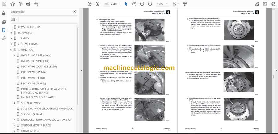
- TRAVEL MOTOR
- Construction
- Assembled cross-sectional view
- Reduction gears
- Tools
- Standard tools
- Bolts
- Equipment
- Sealant
- Production tools
- Tightening torque
- Disassembly and assembly
- Preparation
- General precautions
- Disassembly
- Assembly
- Performance verification testing
- SLEW MOTOR
- Construction
- Hydraulic motor
- Reduction gears
- Brake valve
- Special tools
- Disassembly and assembly
- Inspection and adjustments
- SWIVEL JOINT
- Construction
- Disassembly and assembly
- WIRE HARNESS
- Electrical wiring assembly
- Main unit wiring assembly: 514600003 or later
- Main unit wiring assembly: 514601013 or later
- Floor wiring assembly: 514600003 or later
- Floor wiring assembly: 514601021 or later
- Engine wiring assembly
- Other wire harnesses
- Engine wiring assembly
- Back camera assembly
- 5. TROUBLESHOOTING
- ABOUT THE TROUBLESHOOTING SECTION
- Notes on troubleshooting and servicing
- OVERALL MACHINE
- No operation is possible.
- All systems working, but power insufficient.
- Boom, bucket, slew and arm fail to move or are too slow.
- TRAVELING
- No right or left travel
- Right or left travel speed decelerates and the machine veers to one side.
- 2nd-speed travel is not possible.
- SLEWING
- No slew movement.
- No right or left slew movement.
- Slewing is slow or lacks force.
- Slewing occurs but overrun is large when slewing stops or slewing fails to stop.
- When stopped on a slope, the upper-structure cannot maintain its posture.
- BOOM
- Boom cylinder does not move.
- Boom cylinder is slow or lacks force.
- Spontaneous drop of the boom cylinder is too large.
- ARM
- Arm cylinder does not move.
- Arm cylinder is slow or lacks force.
- Spontaneous drop of the arm is too large.
- BUCKET
- Bucket cylinder does not move or lacks force.
- Spontaneous drop of the bucket is too large.
- BOOM SWING
- Swing cylinder does not move.
- BLADE
- Blade cylinder does not move or lacks force.
- The spontaneous drop of the blade is too large, or the blade cannot support the machine.
- AUXILIARY HYDRAULICS
- The prescribed pressure is not supplied to the 1st auxiliary line
- Prescribed pressure is not supplied to the 2nd auxiliary line.
- Prescribed pressure is not supplied to the 3rd auxiliary line.
- PISTON PUMP
- GEAR PUMP
- CONTROL VALVE
- PILOT VALVE
- SOLENOID VALVE
- CYLINDER
- TRAVEL MOTOR
- SLEW MOTOR
- Hydraulic motor, brake valve
- Parking brake
- SWIVEL JOINT
- 6. OTHER
- MAINTENANCE SOFTWARE MANUAL
- CONTENTS
- 1. OUTLINE
- 2. CONNECTION METHODS
- 2-1. Items needed
- 2-2. Installation method
- 2-2-1. Installation of the PLUS+1 Service Tool
- 2-2-2. Installation of the maintenance tool driver
- 2-3. Connection to the machine and startup of the maintenance software
- 3. DESCRIPTION OF FUNCTIONS
- 3-1. Home
- 3-2. Machine status
- 3-2-1. Controller pin wiring diagrams
- 3-2-2. Inputs
- 3-2-3. Outputs
- 3-2-4. Feedback
- 3-2-5. CAN
- 3-2-6. Error code
- 3-2-7. Error code HVAC
- 3-2-8. Vehicle status
- 3-3. Engine status
- 3-3-1. Engine status
- 3-3-2. Standstill
- 3-4. AUX1
- 3-4-1. AUX1
- 3-4-2. Grip setting
- 3-4-3. Stroke setting
- 3-4-4. Current setting
- 3-4-5. Pressure setting
- 3-4-6. Max relief pressure setting
- 3-5. AUX2
- 3-5-1. AUX2/AUX4
- 3-5-2. Grip setting
- 3-5-3. Stroke setting
- 3-5-4. Current setting
- 3-5-5. Pressure setting
- 3-6. Other
- 3-6-1. Fan drive
- 3-6-2. Coolant
- 3-6-3. Hydraulic
- 3-6-4. Ambient
- 3-6-5. Air conditioner
- 3-6-6. Hydraulic pump
- 3-6-7. Standard mode
- 3-6-8. Power mode
- 3-6-9. Travel in power mode
- 3-6-10. Lift alarm
- 3-6-11. Misc
- 3-6-12. Engine auto stop
- 3-6-13. Pattern change
- 3-6-14. Immobilizer
- 3-6-15. Hourmeter
- 3-6-16. Option
- 3-6-17. Auto grease
- 3-6-18. Test mode
- AIR CONDITIONER
- Compressor assembly
- Condenser assembly
- Air conditioner unit assembly
- Air conditioner unit
- Heater
- CALIBRATION OF 270° CAMERA
- 1. Overview
- 270° camera calibration
- When calibration is required
- 2. Parts needed
- 3. Calibration procedure
- VEHICLE ERROR CODES
- Diagnostics procedures for malfunctions and failure
- Repair procedures
- How to check the detection ports
- VEHICLE ERROR CODES
- TABLE OF ENGINE ERROR CODES
Takeuchi


