Takeuchi TCR50-2 Crawler Dumper Workshop Manual (CAA0E010)(SN 305400002-)
The TCR50-2 crawler dumper spends its life shuttling spoil, rock, and mud on tight, rough jobsites where access is lousy and downtime is expensive. This workshop manual is what I’d pull when I need to strip, repair, and correctly reinstall major components, not just “look something up.” For example, if the dumper starts crabbing sideways after a track motor repair, this book walks you through how to trace the fault, realign the running gear, and verify it’s safe to send back on a slope.
Applications & Use Cases
- Plan a full repair sequence before tearing down major components so you don’t miss hidden brackets, shims, or seals.
- Trace hydraulic issues on travel or dump functions, then isolate whether it’s a valve, line routing, or actuator problem.
- Inspect wear points on undercarriage, pivot joints, and dump mechanism using the manual’s checks as a routine guide.
- Reinstall components safely, verifying torques, clearances, and hose routing so nothing rubs, leaks, or binds.
- Test and adjust controls after repairs to confirm smooth travel, proper dumping, and predictable response.
FAQ
Q: Is this manual practical to use on a tablet in the field?
A: Yes, it’s workable on a tablet; you can zoom diagrams and keep it clean while the machine is apart.
Q: Should I still print pages from it?
A: I usually print the specific procedures I’m doing that day, so they can get greasy without risking the whole manual.
Safety Note
Always lock out, support, and block the dumper securely before working under or around raised or suspended components.
Takeuchi TCR50-2 Crawler Dumper Index:
- REVISION HISTORY
- FOREWORD
- Directional terms: front, rear, left, right
- Machine serial number
- Symbols used in this manual
- Manual structure
- 1. SAFETY
- SAFETY ALERT SYMBOL
- SAFETY PRECAUTIONS
- Observe all safety rules
- Wear safe clothing and protective gear
- Install an extinguisher and a first aid kit
- Lockout/Tagout (LOTO)
- Use the correct tools
- Regularly replace the safety-critical parts
- Explosionproof lighting
- Prohibit access by unauthorized persons
- Prepare the work area
- Keep the machine clean
- Stop the engine before performing maintenance
- Keep clear of the moving fan and belt
- When working under the machine
- When working on the machine
- Secure the engine hood and guard when they are open
- Caution when filling with fuel or oil
- Handling of hoses
- Be careful with hot and pressurized components
- Handling of radiator
- Be careful with oils under pressure
- Release the residual pressure from the hydraulic system before performing maintenance
- Disconnect the battery
- Use caution when handling batteries
- Have a service agent repair welding cracks or other damage
- Checks after maintenance
- Disposing of wastes
- Cautions for handling DEF/AdBlue®
- CAUTIONS WHEN WORKING
- When disassembling or assembling
- When removing/installing the hydraulic unit
- When connecting/disconnecting the hoses or pipes
- Handling of seals
- Pressure adjustment for hydraulic devices
- 2. SERVICE DATA
- DIMENSIONAL DRAWING
- Machine dimensions
- Work dimensions
- SPECIFICATION TABLE
- Performance
- Main dimensions
- Engine
- Power transmission equipment
- Steering equipment
- Brake equipment
- Suspension equipment
- Frame
- Dump equipment
- Instrument
- Switch
- Slew equipment
- Lower machinery
- Hydraulic cylinder
- TABLE OF MASSES
- TABLE OF FUEL AND LUBRICANT
- Diesel fuel
- Lubricant
- Supply oil level
- Handling of DEF/AdBlue®
- PERFORMANCE EVALUATION STANDARD
- Table of standard values
- Table of hydraulic pump assignment
- Hydraulic pump P1
- Hydraulic pump P2
- Hydraulic pump P3
- Hydraulic pump P4
- Hydraulic pump P5
- Performance inspection guideline
- 1. Engine speed
- 2. Hydraulic pressure
- 3. Cylinder speed
- 4. Travel speed (20 m (65.6 ft))
- 5. Straight-ahead travel
- 6. Parking brake operation time
- 7. Slew speed
- TIGHTENING TORQUE
- Hydraulic hose
- Bite-type pipe fitting for steel pipe
- Joint for piping
- Joint for piping (O-ring seal type)
- Bolts and nuts (JIS strength category 10.9)
- HYDRAULIC CIRCUIT DIAGRAM
- ELECTRICAL CIRCUIT DIAGRAM
- Symbols in electrical circuit diagram
- Wire color symbols
- Wire color table
- Schematic diagram
- Serial No.: 305400002 to 305400143
- Serial No.: 305400144 or later
- WIRE HARNESS
- Electrical wiring assembly
- Main unit wiring assembly
- Engine wiring assembly
- Cab wiring assembly
- Wire harness
- Wire harness
- Wire harness
- Upper frame wiring assembly
- Other wire harnesses
- Rear camera assembly
- Heater assembly
- Air conditioner assembly
- Limit switch assembly
- Fuel supply pump assembly
- Cab mounting assembly
- Cab light assembly
- Wire harness
- Wire harness
- Beacon power supply socket assembly
- HYDRAULIC DEVICE LAYOUT DIAGRAM
- 3. FUNCTION
- HST PUMP
- Hydraulic pump
- Control section
- Charge check/high-pressure relief valve assembly
- Charge check valve
- High-pressure relief valve
- Charge relief valve
- GEAR PUMP
- CONTROL VALVE
- Load check valve
- Spacer section
- Main relief valve
- Port relief valve
- PILOT VALVE (CONTROL LEVER)
- PROPORTIONAL CONTROL SOLENOID VALVE
- SOLENOID VALVE
- Solenoid valve
- Relief valve
- AUTO-TENSION VALVE
- Check function
- Relief valve
- CYLINDERS
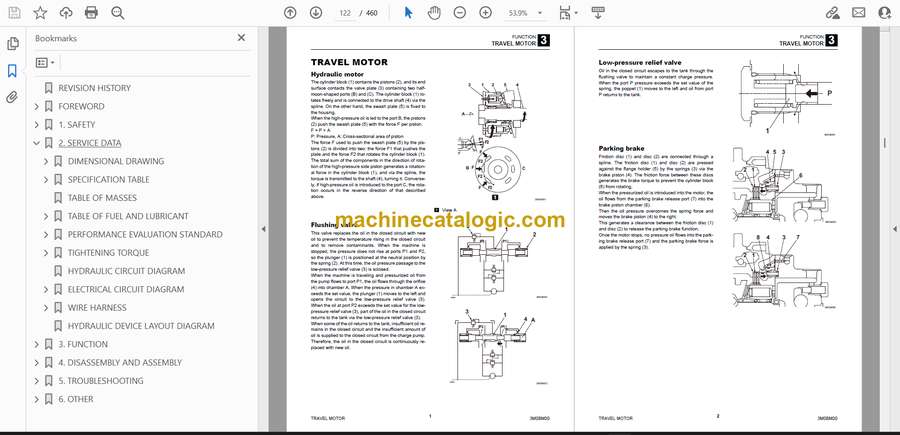
- TRAVEL MOTOR
- Hydraulic motor
- Flushing valve
- Low-pressure relief valve
- Parking brake
- 2-speed control valve
- Swash plate
- Automatic 2-speed
- Check valve
- Reduction gears
- SLEW MOTOR
- Hydraulic motor
- Relief valve
- The 1st stage
- The 2nd stage
- Make-up valve
- Parking brake
- Timer valve
- Reduction gears
- SWIVEL JOINT
- 4. DISASSEMBLY AND ASSEMBLY
- SERVICE STANDARD
- Carrier roller
- Track roller
- Front idler
- Sprocket
- Dump cylinder
- Pin to bushing clearance
- About replacement of pin and bushing
- DRIVE EQUIPMENT
- Assembly of engine
- Engine assembly
- Radiator assembly
- Urea tank assembly
- Construction diagram
- Removal of engine
- Installation of engine
- Assembly of hydraulic pump
- Construction diagram
- Removal of hydraulic pump
- Installation of hydraulic pump
- Bleeding air from HST pump
- Assembly of fuel tank
- Assembly of fuel supply oil pump
- Construction diagram
- Removal of fuel tank
- Installation of fuel tank
- Assembly of battery
- Construction diagram
- Removal of battery
- Installation of battery
- TRAVEL SYSTEM
- Removing the crawler
- Installing the crawler
- Removing the carrier roller
- Installing the carrier roller
- Removing the track roller assembly
- Installing the track roller assembly
- Removing the idler
- Installing the idler
- Removing the travel motor
- Installing the travel motor
- SLEW EQUIPMENT
- Slew motor
- Removing the slew motor
- Installing the slew motor
- Slew bearing
- Removing the slew bearing
- Installing the slew bearing
- Swivel joint
- Removing the swivel joint
- Installing the swivel joint
- UPPER FRAME
- Assembly of main unit
- Assembly of cover
- Construction diagram
- Removal of covers
- Installation of covers
- Assembly of cab mounting
- Construction diagram
- Removal of cab assembly
- Installation of cab assembly
- Removal of glass
- Installation of glass
- OPERATING DEVICE
- Hydraulic pilot unit
- Valve bracket (Left)
- Valve bracket (Right)
- Control box L
- Control box R
- Foot accelerator pedal
- Cluster gauge
- ATTACHMENTS
- Dump Body
- Removing the dump cylinders
- Installing the dump cylinders
- HYDRAULIC TANK
- Removing the hydraulic tank
- Installing the hydraulic tank
- HST PUMP
- GEAR PUMP
- Construction
- Disassembly and assembly
- General precautions
- Disassembly
- Assembly
- Inspection and adjustment
- Checking the parts
- Test operation
- Measuring the discharge volume
- CONTROL VALVE
- Construction
- Dump section
- Slew section
- Inlet section
- Main relief valve
- Disassembly and assembly
- General precautions
- Disassembly
- Inspection and adjustments
- Checking the parts
- Adjusting the main relief valve pressure
- PILOT VALVE
- Construction
- Special tools
- Installation jig A
- Installation jig B
- Disassembly and assembly
- Inspection and adjustments
- PROPORTIONAL CONTROL SOLENOID VALVE
- Construction
- Disassembly and Assembly
- Inspection and adjustment
- SOLENOID VALVES (LEVER LOCK, SPEED SHIFT, PARKING BRAKE)
- Construction
- Disassembly and Assembly
- Inspection and adjustment
- AUTO-TENSION VALVE
- Construction
- Disassembly and assembly
- CYLINDER
- Construction
- Dump cylinder
- Tensioning cylinder
- Disassembly and assembly
- Special tools
- Disassembly
- Assembly
- Inspection and adjustment
- Inspection after disassembly
- Inspection after assembly
- TRAVEL MOTOR
- Construction
- Hydraulic motor
- Reduction gears
- Flushing valve, automatic 2-speed mechanism, check valve
- Special tools
- Disassembly and assembly
- Disassembly
- Assembly
- Inspection and adjustments
- SLEW MOTOR
- Construction
- Hydraulic motor
- Reduction gears
- Brake valve
- Disassembly and assembly
- General precautions
- Slew motor
- Hydraulic motor
- Reduction gears
- Assembly
- Hydraulic motor
- Reduction gears
- Slew motor
- Inspection and adjustments
- SWIVEL JOINT
- Construction
- Hydraulic motor
- Special tools
- Disassembly and assembly
- General precautions
- Disassembly
- Assembly
- Inspection and adjustment
- Inspection and actions
- Use limit for parts
- WIRE HARNESS
- MAIN UNIT HYDRAULIC PIPING
- Main unit hydraulic piping assembly
- Construction diagram
- <Table of connections>
- Slew dump piping assembly
- Construction diagram
- <Table of connections>
- 5. TROUBLESHOOTING
- GEAR PUMP
- PILOT VALVE
- PROPORTIONAL SOLENOID VALVE (ACTIVE POWER CONTROL, 1ST AUXILIARY LINE PIPING)
- SOLENOID VALVE (LEVER LOCK, VARIABLE TRAVEL SPEED, PARKING BRAKE)
- AUTO TENSION VALVE
- CYLINDER
- TRAVEL MOTOR
- Hydraulic motor
- Parking brake
- High pressure relief valve
- Low pressure shuttle valve
- 2nd speed control function
- Low pressure relief valve
- SLEW MOTOR
- Slew motor function
- Function of motor internal valve
- Parking brake and hydraulic pressure timer function
- SWIVEL JOINT
- TROUBLESHOOTING
- HST TROUBLESHOOTING
- 6. OTHER
- MAINTENANCE SOFTWARE MANUAL
- CONTENTS
- 1. OVERVIEW
- 2. CONNECTION METHOD
- 2-1. Parts needed
- 2-2. Installation method
- 2-2-1. Installation of “PLUS+1 Service Tool”
- 2-2-2. Installation of maintenance tool driver
- 2-3. Connection to work machine and startup of maintenance software
- AIR CONDITIONER
- Assembly of compressor
- Assembly of condenser
- Assembly of air conditioner unit
- Construction diagram
- Removing compressor
- Installing compressor
- Removing receiver dryer
- Installing receiver dryer
- Removing condenser
- Installing condenser
- Removing air conditioner unit
- Installing the air conditioner unit
- AIR CONDITIONER SYSTEM
- Overview of System Operation
- Truck and Heavy Equipment Systems
- Air Conditioner—System Operation
- Heater System Operation
- Environmental Effects on System Operation
- Chapter Review
- Inspection and Maintenance without gauges
- Discussion of Inspection & Maintenance Survey Results
- Visual Inspection – System Off
- Electrical System Inspection
- Performance Inspection – Engine Running
- Heater System Inspection
- Preventive Maintenance Worksheet
- Chapter Review
- Troubleshooting & Service Procedures
- Troubleshooting Overview
- The Key–Understanding System Function
- A Troubleshooting Example
- Manifold Gauge Set Installation
- Troubleshooting by Manifold Gauge Set Readings
- Review of Frequent Problem Areas
- Conclusion
- Electrical wiring diagram
- VEHICLE ERROR CODES
- Diagnostics procedures for malfunctions and failure
- Repair procedures
- How to check the detection ports
- TABLE OF VEHICLE ERROR CODES
- TABLE OF ENGINE ERROR CODES
Takeuchi


