Takeuchi TL230 Track Loader Workshop Manual (CU5E002) (SN 223100001-)
The TL230 spends its life in mud, demolition rubble, and tight construction sites, so when something’s off, you need a clear sequence to get in, fix it, and button it back up safely. This Takeuchi TL230 Track Loader Workshop Manual (CU5E002) is what I’d use to trace a hydraulic leak, pull a drive motor, or realign a loader arm after a hard hit. For example, if the loader starts creeping or losing lift, this book walks you through a structured diagnosis, then the correct teardown and reinstallation checks so you don’t create a second problem while fixing the first.
Applications & Use Cases
- Plan a repair sequence before tearing down major components like the undercarriage, drive motors, or loader arms.
- Trace and isolate hydraulic issues, then verify routing and sealing when hoses, valves, or cylinders are refitted.
- Inspect wear points—pins, bushings, rollers, and track components—using the manual’s guidance to decide repair vs. replace.
- Align and reinstall controls, pedals, and linkages so the machine tracks straight and responds evenly after work.
- Test and bleed systems after repairs to confirm pressures, responses, and safety functions are back where they should be.
FAQ
Q: Can I use this manual on a tablet in the field?
A: Yes, it’s practical on a tablet; you can zoom in on diagrams and keep it open next to the machine while you work.
Q: Is it worth printing sections of this manual?
A: I’d print the procedures you use often or any big teardown, so you can mark notes, oil types, and torque reminders right on the page.
Safety Note
Always support raised components securely and relieve system pressures before loosening any fittings or hardware.
Takeuchi TL230 Track Loader Index:
- 1 SAFETY
- Safety alert symbol
- Safety precautions
- Cautions when working
- 2 SERVICE DATA
- Dimensional drawing
- Specifications tables
- Lubricant and fuel chart
- Performance criteria
- Tightening torque
- Hydraulic circuit diagram
- Electrical wiring diagram
- Wire harness diagram
- 3 FUNCTION
- HST pump
- Gear pump
- Control valve
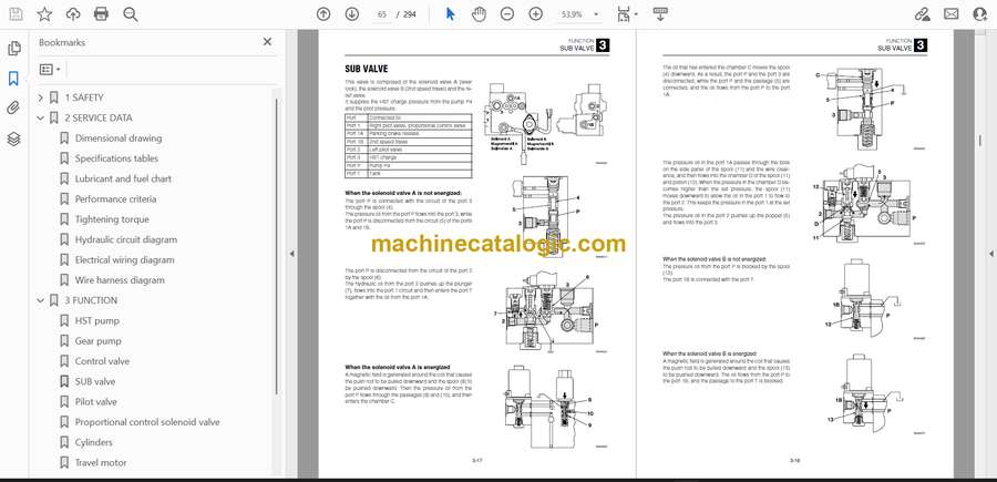
- SUB valve
- Pilot valve
- Proportional control solenoid valve
- Cylinders
- Travel motor
- Air conditioner system
- 4 DISASSEMBLY AND ASSEMBLY
- Service standards
- Drive system
- Travel system
- Frame
- Control system
- Attachments
- Hydraulic tank
- HST pump
- Gear pump
- Gear pump (High flow)
- Control valve
- Control valve (High flow)
- Sub valve
- Pilot valve
- Proportional control solenoid valve
- Cylinders
- Travel motor
- 5 TROUBLESHOOTING
- Overall machine
- No operation is possible.
- All systems working, but insufficient power.
- Lift arm and bucket fail to move or are too slow.
- Traveling
- Traveling fails.
- Right or left travel speed decelerates and the machine veers to one side.
- Operating temperature of the travel system is too high.
- 2nd speed travel is not possible.
- Lift arm
- Arm cylinder fails.
- Arm cylinder is slow or the power is insufficient.
- When the control lever is pulled slowly, the lift arm drops once.
- Spontaneous drop of the lift arm is too large.
- Bucket
- Bucket cylinder fails to move.
- Bucket cylinder is slow or the power is insufficient.
- Spontaneous drop of the bucket is too large.
- Auxiliary hydraulics
- Proportional control is not possible
- HST pump
- Gear pump
- Control valve
- Sub valve
- Pilot valve
- Proportional control solenoid valve
- Cylinders
- Travel motor
- Air conditioner
- CLUSTER GAUGE
Takeuchi


