Format: PDF (Printable Document)
File Language: English
File Pages: 160
File Size: 19.03 MB (Speed Download Link)
Brand: Kato
Model: APC100
Book No: 370530
Type of Document: Service Manual
$ 45
Introduction
Chapter 1 Brief description of the APC 100
1 Glossary
2 Summary of the APC 100 system
1-2-1 System composition
1-2-2 Component devices of the APC 100 system and their locations
1-3 APC 100 system control circuit
1-3-1 Electrical circuit diagram
1-3-2 Relay board
1-4 Layout of connectors and their signal names
1-4-1 Combination monitor
1-4-2 Controller
1-4-3 Relay box
1-4-4 Accelerator actuator wiring connectors
1-4-5 Engine speed sensor wiring connector
1-4-6 Solenoid valve block wiring connectors
Chapter 2 Troubleshooting
2-1 External appearance of the main components of the APC 100 system
2-2 Arrangement of internal components of the main components of the APC 100 system
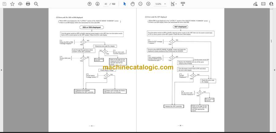
2-3 Error message screen displays and error code numbers
2-4 Troubleshooting
2-4-1 Troubleshooting by error codes
2-4-2 Troubleshooting by symptoms
2-5 ADJUST MODE
2-5-1 How to switch to the ADJUST MODE menu screen
2-5-2 The ADJUST MODE menu and its display
2-5-3 Data display by menu from the ADJUST MODE menu
2-6 Checking and adjustment
2-6-1 ROM software code checking
2-6-2 Checking actual engine speed
2-6-3 Adjusting the engine control system
2-6-4 Checking and confirmation of Rated Controlled Engine Speed and No-load Controlled Engine Speed
2-6-5 Checking the proportional electromagnetic control valve operation system
2-6-6 Checking pump 1 pressure (P1)
2-6-7 Checking pump 2 pressure (P2)
2-6-8 Checking the function of the APC switch the accelerator backup switch and the manual accelerator switch
Chapter 3 Procedures for replacing component parts of the combination monitor or APC controller
3-1 How to replace the ROM bulbs and fuses of the combination monitor
3-1-1 How to detach the combination monitor
3-1-2 How to disassemble the combination monitor
3-1-3 Handling precautions for ROM extraction and insertion
3-1-4 How to order ROMs
3-1-5 How to replace the bulbs
3-1-6 How to replace the fuse
3-2 How to replace the ROM and fuse of the APC controller
3-2-1 How to open the side cover of the control panel
3-2-2 How to remove the APC controller cover
3-2-3 Handling precautions for ROM extraction and insertion
3-2-4 How to order ROMs
3-2-5 How to replace the fuse
3-2-6 How to replace relay RL1
3-3 How to replace the fuel gauge engine coolant temperature gauge and hour meter
3-3-1 How to remove the meter panel
3-3-2 How to remove the hour meter
3-4 How to replace the display panel
3-4-1 How to remove the display panel
3-5 How to replace the front cover and switch-board
3-5-1 How to remove the switch-board
Chapter 4 Replacement and adjustment of the accelerator actuator
4-1 Accelerator actuator specification for each model
4-2 Mounting and adjustment of the accelerator actuator
4-3 Check the APC 100 system before supplying power
4-4 Check the status of the APC 100 system
4-5 Adjust the engine control circuit
Data file section
1 Specifications for detector switches and sensor
2 Table of standard specification values for APC 100 system acceleration control
2-1 STD specification engine mount
2-2 ES specification engine mount
3 Unit conversion table


