Develon DA30-5 Articulated Dump Truck Shop Manual (Pre Series 720402; 740401, Series 721001 – up; 741001- up;)
These DA30-5 trucks live in rough places—quarries, landfills, big earthmoving jobs—hauling heavy loads all day over torn-up ground. This shop manual is what you use when you’re past simple checks and you’re ready to tear into the driveline, axles, steering, and brakes without guessing. Say you’ve got a nasty driveline vibration: with this, you’ll plan the teardown, trace the issue, inspect each component on the bench, and then reassemble it so the shafts line up and don’t eat themselves in a week.
Applications & Use Cases
- Plan a major teardown so you can route hoses, harnesses, and lines cleanly and know what has to come off first without fighting every fastener.
- Check and verify axle, hub, and suspension components while they’re apart, so worn bushings or shims don’t get buried back inside.
- Follow general torque and tightening sequences to align housings and frames, so you don’t twist something and cause premature failures.
- Isolate steering or brake problems, then test and bleed systems properly after you’ve swapped valves, cylinders, or pumps.
- Inspect articulation joints and frame points during rebuild, making sure pins, bearings, and shims go back in the right order.
FAQ
Q: Is this a PDF I can search on my laptop, or just a scanned picture?
A: It’s typically a searchable PDF, so you can jump to sections, but some diagrams may behave like images.
Q: Can I print just a few sections to take out to the truck?
A: Yes, most folks print the pages for the job they’re doing, stick them in a sleeve, and keep the main file on a computer.
Safety Note
Always support the truck and dump body with proper stands and locks before you crawl under or start loosening any major components.
Develon DA30-5 Articulated Dump Truck Index:
- Shop manual Front cover DA30-5 image
- SM-MX533347_DA30-5_SN7X1001-up_20.10.2017
- DA30 Final- 0 – General (VERKST-BOK – 1021048 – 1 – B) – 1
- Foreword
- Torque limit table
- Types of sealing-/locking compounds and lubricants
- Safety in workshop
- Working on machine
- Personal Protective Equipment (PPE)
- Vibration
- Injurious noise
- Organic solvent
- Fueling
- Fire and Explosion Prevention
- Fire and explosion risks
- In case of Fire
- Coolant
- Refrigerant
- Air pollution
- Operation in extreme conditions
- Liquid or gas under high pressure
- Asbestos
- Lead
- Battery hazard prevention
- Disposal of hazardous materials
- Jacked up vehicle or bodywork
- Crushing and Cutting Danger
- Heavy units
- More than one person working with the same object
- Involuntary start of electric motors etc.
- Rotating parts
- Splinters, flying object When using certain tools
- Springs under load
- Precautions for disassembly and assembly
- DA30DA40 Final- 1 Engine PDE (VERKST-BOK – 1030216 – 1 – G) – 1
- Engine identification
- Removal of engine assembly
- Lifting the engine
- Starting the engine
- Important information about the fuel
- Fuel system Tier2 (PDE)
- Schematic diagram of the fuel system Tier2
- Overflow valve
- General
- FUEL
- Temperature Dependency of the Fuel
- Fuel filter
- Changing the fuel filter
- Water separating prefilter PDE
- changing the water separating fuel filter
- Bleeding the fuel system
- Feed pump
- Renewing the control unit
- Removing the ECU wiring Tier2
- Cylinder head – PDE System Tier2
- Cylinder head, parts view. PDE Tier2
- Special tools
- Valve mechanism
- Dismantling
- Renewing the valve stem seal
- Replacement of valve seats
- Machining the valve seats insert
- Renewing the valve guides
- Renewing PDE unit injector sleeves
- Assembly
- Fitting
- Unit injector fitting and flywheel access
- Valve and unit injector adjustment with PDE
- Order of adjustment for valve clearance and PDE unit injectors
- Flywheel readings (DA40)
- Flywheel readings (DA30)
- Adjusting the valve clearance and unit injectors
- Turbocharger
- Measuring radial clearance and axial clearance
- Renewing the turbocharger
- General
- Changing oil filter
- Oil analysis
- Checking oil level
- Changing the oil
- Special tools
- Pistons and cylinder liners
- Special tools
- Connecting rods
- Removing and dismantling connecting rods and pistons
- Renewal of bearing bushing in connecting rod
- Pistons
- Assembling piston and connecting rod
- Cylinderblock
- Cylinder liner
- Removing the cylinder liners
- Measuring the cylinder liner height
- Measuring the cylinder wear ridge and cylinder bore
- Fitting the cylinder liners
- Fitting the piston and connecting rod
- Flywheel and flywheel housing
- Special tools
- Removing the flywheel
- Renewing the rear crankshaft seal
- Removing the flywheel housing
- Fitting flywheel housing
- Fitting the flywheel
- Flexible coupling
- Safety instructions
- Functional description
- Disassembly and dismantling the coupling
- Assembling the coupling
- Installation instructions
- Friction disk, Friction ring
- Timing gear – 13 and 9 liter
- Gear drive
- Belt drive collant pump, generator and AC compressor
- Checking the Drive Belt
- Check for leaks
- Renewing the seal in the front cover
- Crankshaft damper
- Timing gear, view exploded
- Special tools
- Intermediate gear
- Camshaft gear
- Crankshaft gear
- Camshaft
- Replacement of camshaft bearing
- Crankshaft
- Removal
- Fitting
- Adjust – Machining the crankshaft
- Lubrication system
- General
- Oil pump
- Lubrication oilways
- Oil pressure
- Oil cooler, engine
- Oil cooler view See 010009
- Renewing seals and leakage testing
- Oil filter
- Centrifugal oil cleaner
- Dismantling and assembly
- Oil mist separator
- General
- High levels of oil carryover
- Crankcase pressure measurement
- Oil mist separator exploded view
- Oil mist separator disassemble
- Check – Rotational speed on oil mist separator
- Alternator 100 A
- Check
- Output test
- Renewal – Bearing and carbon brushes
- Oil pump, brake cooling circulate (DA40)
- Exploded view
- Disassemble and overhaul the oil pump
- Checking and renewing parts
- Oil circulate pump assemble.
- Renewing the gasket
- Cooling fan
- View of the radiator system DA40
- Cooling system
- Principal view of the cooling system
- Circulation
- Coolant
- Checking Coolant Level
- Pressure testing the cooling system
- Delivery valve
- External leakage
- Internal leakage
- Checking the Antifreeze Level
- Changing Coolant
- Filling Coolant
- Cleaning the Cooling System
- Removing oil cooler
- Disassemble the cooling unit
- Thermostat and thermostat housing
- Thermostat
- Coolant pump
- External cleaning
- Internal cleaning
- Technical data DC13 with PDE
- General data
- Technical data DC9 with PDE
- General data
- Troubleshooting ECOM / Canbus
- To do:
- Troubleshooting, -basic info.
- Troubleshooting fuel system
- Troubleshooting Guide
- Diagnostic procedure
- Use of diagnostic kit
- Connection point Canpc + Testman
- Can bus overview
- SDP3 Scania dagnostic
- Retrieving data from VCU
- Troubleshooting Manual
- White smoke
- White smoke, water vapour
- White smoke, water vapour
- Black smoke on starting
- Blue smoke
- Fuel in the oil
- Oil in coolant
- Coolant/water in oil
- Low oil pressure
- High oil pressure (engine warmed up)
- Abnormal wear (liner, piston rings, etc.)
- Vibration, no driven components engaged
- Vibration when the clutch or reverse gear is engaged
- Vibration when alternator is in operation
- Engine speed hunting – single-speed engines with RQ governor
- Engine speed hunting – single-speed engines with RSV governor
- Delivery pipe fractures
- External corrosion on cylinder liner
- Engine difficult to start
- Fluid stroke
- Knocking/noise
- High oil consumption
- High fuel consumption
- Low compression
- Low engine output
- Hot engine
- Cold engine
- Coolant loss
- Polluted coolant
- Polluted coolant
- High oil temperature
- High exhaust temperature
- Low charge air pressure
- Low fuel pressure
- Low system voltage
- High system voltage
- External oil leakage
- External fuel leakage
- External coolant leakage
- Oil pressed out via crankcase ventilation
- Turbocharger breakdown
- Compressed air system
- DA30DA40 Final- 1 Engine XPI (VERKST-BOK – 1030217 – 1 – F) – 1
- Engine identification
- Removal of engine assembly
- Lifting the engine
- Starting the engine
- XPI Fuel system DA30/40
- Route of the fuel on 9 and 13 liter engines
- Fuel filter and water separation filter
- Changing the fuel filter
- Water separating prefilter
- changing the water separating fuel filter
- Overflow valve
- Fuel system components
- Schematic diagram of the fuel system:
- Important information about the fuel
- Exhaust system XPI
- Introduction System overview
- Control system for exhaust gas aftertreatment
- Control unit EEC3
- System overview for mechanics
- System overview for electronics
- Ad blue filter change
- Reductant doser
- Start-up instruction for new SCR Pump
- Reductant pump, function
- Renewing the control unit
- Removing the ECU wiring Tier2
- Common rail Injectors Tier4/XPI
- Cylinder head – XPI system Tier4
- Cylinder head, parts view. XPI system Tier4
- Injector Scania XPI
- Order of adjustment for 13 liter engines
- Valve adjustment DC13 with XPI
- Cylinder configuration, 6 cylinder engines
- Valve adjustment DC9 with XPI
- Cylinder configuration, 5 cylinder engines
- Turbocharger
- Measuring radial clearance and axial clearance
- VGT (Variable geometry turbo)
- VGT Removal
- VGT fitting
- General
- Changing oil filter
- Oil analysis
- Checking oil level
- Changing the oil
- Special tools
- Pistons and cylinder liners
- Special tools
- Connecting rods
- Removing and dismantling connecting rods and pistons
- Renewal of bearing bushing in connecting rod
- Pistons
- Assembling piston and connecting rod
- Cylinderblock
- Cylinder liner
- Removing the cylinder liners
- Measuring the cylinder liner height
- Measuring the cylinder wear ridge and cylinder bore
- Fitting the cylinder liners
- Fitting the piston and connecting rod
- Flywheel and flywheel housing
- Special tools
- Removing the flywheel
- Renewing the rear crankshaft seal
- Removing the flywheel housing
- Fitting flywheel housing
- Fitting the flywheel
- Flexible coupling
- Safety instructions
- Functional description
- Disassembly and dismantling the coupling
- Assembling the coupling
- Installation instructions
- Friction disk, Friction ring
- Timing gear – 13 and 9 liter with XPI
- Gear drive
- Belt drive collant pump, generator and AC compressor
- Checking the Drive Belt
- Check for leaks
- Renewing the seal in the front cover
- Crankshaft damper
- Timing gear, view exploded
- Special tools
- Intermediate gear
- Camshaft gear
- Crankshaft gear
- Camshaft
- Replacement of camshaft bearing
- Crankshaft
- Removal
- Fitting
- Adjust – Machining the crankshaft
- Lubrication system
- General
- Oil pump
- Lubrication oil-ways
- Oil pressure
- Oil cooler, engine
- Oil cooler view
- Renewing seals and leakage testing
- Oil filter
- Centrifugal oil cleaner
- Dismantling and assembly
- Oil mist separator
- General
- High levels of oil carryover
- Crankcase pressure measurement
- Oil mist separator exploded view
- Oil mist separator disassemble
- Check – Rotational speed on oil mist separator
- Alternator 100 A
- Check
- Output test
- Renewal – Bearing and carbon brushes
- Oil pump, brake cooling circulate (DA40)
- Exploded view
- Disassemble and overhaul the oil pump
- Checking and renewing parts
- Oil circulate pump assemble.
- Renewing the gasket
- Cooling fan
- View of the radiator system DA40
- Cooling system
- Principal view of the cooling system
- Circulation
- Coolant
- Checking Coolant Level
- Pressure testing the cooling system XPI
- Delivery valve
- External leakage
- Internal leakage
- Checking the Antifreeze Level
- Changing Coolant
- Filling Coolant
- Cleaning the Cooling System
- Removing oil cooler
- Disassemble the cooling unit
- Thermostat and thermostat housing
- Thermostat
- Coolant pump
- External cleaning
- Internal cleaning
- Technical data DC13 with XPI
- General data
- Technical data DC9 with XPI
- General data
- Troubleshooting ECOM / Canbus
- To do:
- Troubleshooting, -basic info.
- Troubleshooting fuel system
- Troubleshooting Guide
- Diagnostic procedure
- Use of diagnostic kit
- Connection point Canpc + Testman
- Can bus overview
- SDP3 Scania dagnostic
- Retrieving data from VCU
- Troubleshooting Manual
- White smoke
- White smoke, water vapour
- White smoke, water vapour
- Black smoke on starting
- Blue smoke
- Fuel in the oil
- Oil in coolant
- Coolant/water in oil
- Low oil pressure
- High oil pressure (engine warmed up)
- Abnormal wear (liner, piston rings, etc.)
- Vibration, no driven components engaged
- Vibration when the clutch or reverse gear is engaged
- Vibration when alternator is in operation
- Engine speed hunting – single-speed engines with RQ governor
- Engine speed hunting – single-speed engines with RSV governor
- Delivery pipe fractures
- External corrosion on cylinder liner
- Engine difficult to start
- Fluid stroke
- Knocking/noise
- High oil consumption
- High fuel consumption
- Low compression
- Low engine output
- Hot engine
- Cold engine
- Coolant loss
- Polluted coolant
- Polluted coolant
- High oil temperature
- High exhaust temperature
- Low charge air pressure
- Low fuel pressure
- Low system voltage
- High system voltage
- External oil leakage
- External fuel leakage
- External coolant leakage
- Oil pressed out via crankcase ventilation
- Turbocharger breakdown
- Compressed air system
- Kopi av DA30DA40 Final- 2 Transmission (VERKST-BOK – 1017576 – 1 – E) – 1
- General
- Structure of the Repair Manual
- Denomination of standard dimensions
- Conversion table
- Torque limits for screws.
- Table
- Labeling of type plate
- Information on spare parts ordering
- Configuration of transmission
- Transmission schematics and gear schematics
- Gear schematics
- Measuring points and connections
- Table
- Measuring points for pressure oil and temperature
- Installation sheet
- Specjal tools for disassembly and reassembly
- Commercial tools for disassembly and reassembly
- Removal of transmission, disassembly
- Disassemble the structure bar
- Disassemble the hydraulic hoses
- Positioning for disassembly and reassembly
- Removal and refitting various components
- Transmission
- LKV axle insert
- Separate axle insert LKV from transmission
- Removal of speed sensor n4-output
- Disassembly of shifting block I and speed sensors
- Engine connection
- Oil supply
- Removal of shifting block II, valve block primary
- pump and retarder
- Retarder
- Valve block
- Shifting block II
- Primary pump
- Output to front and rear axle
- Output to front axle with axle insert LKV
- Output to front axle without axle insert LKV
- Output to rear axle
- Power take-off
- Version with 1st PTO
- Emergency steering pump
- Planetary drive “F”
- Separate planetary drive from housing II
- Removal input shaft and clutches
- Separate housing I and housing II
- Housing I
- Differential “G”
- Clutches “V”; “R”; “A”; “B”; “C”; “D”; “E”
- Housing II
- Clutches „V“; „R“; „A“; „B“; „C“; „D“; „E“ and Differential
- Clutch “E”
- Clutch “R”
- Idler
- Gear
- Clutch
- Clutch “B“
- Idler/Gear
- Gear
- Clutch
- Clutch “V“
- Clutch “C“
- Idler
- Gear
- Clutch
- Clutch “D“
- Idler
- Gear
- Clutch
- Clutch “A“
- Idler
- Gear
- Clutch
- Differential ”G“-”DA40 F“
- Differential without axle insert LKV ”G“
- Differential ”G“-”DA30 F“
- Differential with axle insert LKV ”G“
- Reassembly
- Clutches „V“; „R“; „A“; „B“; „C“; „D“; „E“ and Differential
- Clutch ”E“
- Clutch “R“
- Clutch “B“
- Clutch “V“
- Clutch “C“
- Clutch “D“
- Clutch “A“
- Differential ”G“-”DA40 F“
- Differential without axle insert LKV ”G“
- Differential ”G“-”DA30 F“
- Differential with axle insert LKV ”G“
- Installation input shaft and clutches
- Housing II
- Clutches “V”;“R”;“A”;“B”;“C”;“D”;“E”
- Housing I
- Assemble housing I and housing II
- Oil supply
- Shifting block II
- Valve block
- Retarder
- Primary pump
- Installation retarder, primary pump, valve block and shifting block II
- Engine connection
- Planetary drive “F”
- Planetary drive
- Mount planetary drive to housing II
- Output to front and rear axle
- Output to front axle with axle insert LKV ”DA30 F“
- Output to front axle without axle insert LKV ”DA40 F“
- Output to rear axle
- Power take-off
- Version with 1st Power take-off (PTO)
- PTO-gear – 1st power take-off
- PTO-input shaft
- Emergency steering pump
- Version with emergency steering pump
- Reassembly of shifting block I and speed sensors:
- Shifting block I
- Refitting of speed sensor n4-output
- Refitting breather, Oil sight level glass, Cover plate and screw plug
- Version with connection 1st PTO
- Refitting of LKV axle insert
- Disassembly of LKV Axle Insert ”DA30 F“
- Disassembly
- Reassembly of LKV Axle Insert ”DA30 F“
- Resassembly
- Determination of shim for contact pattern
- Reassembly of pinion
- Reassembly of differential
- Setting of backlash/crown wheel set and bearing rolling torque/differential
- Contact pattern check (Fig. 848 and 849)
- Preassembly and reinstallation of flange shaft
- Contact pattern examples of Gleason Tooth System
- Field of application:
- Ideal contact pattern:
- Contact pattern setting:
- Flank glossary:
- EXAMPLE 1: DEDENDUM TOOTH POSITION
- EXAMPLE 2: ADDENDUM TOOTH POSITION
- EXAMPLE 3: “LINE” CONTACT PATTERN
- Transmission assembly
- Clutch calibration
- DA30 Final- 3 Drive line (VERKST-BOK – 1017577 – 1 – C) – 1
- Introduction
- General
- Structure of the Repair Manual
- Denomination of standard dimensions
- Conversion table
- Tightening torques for nuts and bolts.
- Table
- Drive line components
- Front reduction gear
- Parts list
- Front reduction gear cross section
- NAF special Tools for
- Assembly
- Drive shafts
- Front frame
- Rear frame
- Mounting the bearings on the intermediate shaft (B)
- Front differential and transmission
- Brakes
- Service brakes
- Service brake description
- Testing of parking brake
- Remove the Linings (→7×1145)
- Remove the Linings (7×1146→)
- Disassembly the park brake unit (→7X1145)
- Assembly the park brake unit.
- Disassembly the park brake unit from dump truck (7X1146→)
- Disassembly the park brake unit.
- Assembly the park brake unit
- Assembly the park brake
- Adjust the Initial Caliper Clearance (→7X1145)
- Adjust the Initial Caliper Clearance (7×1146→)
- Park brake Maintenance (→7X1145)
- Disc
- Troubleshooting Park brake
- Rear differential
- Rear Differential
- Exchange of the complete rear differential
- Safety precautions.
- Repairs on the rear differential
- Exchange of crown gear / Pinion (7×1001-7×10²⁰)
- Exchange of crown gear / Pinion (7×10²¹ – up)
- Determining thickness of the adjusting washer (44)
- Determining thickness of the adjusting washer (45)
- Pinion bearing adjustment
- Backlash and crown gear bearing adjustment
- Checking contact pattern
- Exchange shaft seals
- Exchange of differential cage (compensating gearbox)
- Differential lock
- Planetary drive
- Complete exchange of planetary cage
- Exchange of sun gear shaft
- Testing and Adjusting of Thrust Stud Adjustment
- Exchange of Planetary Studs and Gears
- Exchange of ring gear carrier
- Wheel bearings
- Gear bearing exchange
- Gear bearing adjustment
- Brake
- Check disc’s wear
- Exchange of the piston seals for the operating brake
- Exchange of brake disks and pressure springs for the operating brake
- Tandem bearings
- Exchange of slewing ring
- Exchange of seal
- Exchange of axle beam
- Gear drive in tandem housing
- Exchange of bearing (84)
- Exchange of gear (43) and bearing (89) / (90)
- Exchange of gears (86)
- Checking clearance in the Tandem bearing.
- View of the Tandem bearing
- Special Tools for Mox 08 axle (7×1001 – 7×10²⁰)
- Special Tools for Mox 17 axle (7×10²¹ – up)
- DA30DA40 Final- 4 Lubrication (VERKST-BOK – 1017579 – 1 – A) – 1
- Lubrication system parts
- Greasing cycles
- Lubrication Points on DA series
- Grease pressure switch
- The 5/2 way valve
- The relief valve
- The minimum level switch
- System test
- Introduction
- The single-test cycle
- The continuous-test cycle
- Warning signal
- Maintenance
- Regularly checks of the greasing system
- Bleeding the pump
- Bleeding the system
- Technical data
- Dimensions of the Twin Pump
- Central lubrication main unit, (overview)
- DA30DA40 Final- 5 Hydraulic system (VERKST-BOK – 1017580 – 1 – A) – 1
- DA30DA40 Final- 6 Electrical system (VERKST-BOK – 1017581 – 1 – G) – 1
- DA30 Final- 7 Front frame (VERKST-BOK – 1017582 – 1 – A) – 1
- 7.1 Introduction
- 7.2 Front Axle Suspension
- Overview of the front axle suspension
- View of the front axle suspension
- Disassemble of the front axle arm
- 7.2.1 Shock Absorber
- 7.2.2 Chain Limiter
- 7.2.3 Rubber Cushion
- 7.2.4 Panhard Bar
- 7.2.5 Suspension Bearing
- 7.2.6 Cross Tube Bushings
- 7.3 Articulation Hinge System
- 7.3.1 Articulation Bearing
- 7.3.2 Articulation bearing assembly
- 7.3.3 Articulation Hinge
- 7.4 Fenders, Mudguards and Bonnet
- 7.4.1 Fender RH
- 7.4.2 Fender LH
- 7.4.3 Mudguard
- 7.4.4 Bonnet Lock
- 7.4.5 Bonnet
- 7.4.6 Bonnet adjustment and control
- 7.5.1 Cab Removal
- 7.5.2 Cab Ventilation Control Panel
- 7.5.3 Cab Ventilation Unit
- 7.5.4 Cab Door
- 7.5.5 Door Damper Cylinder
- 7.5.6 Steering Column
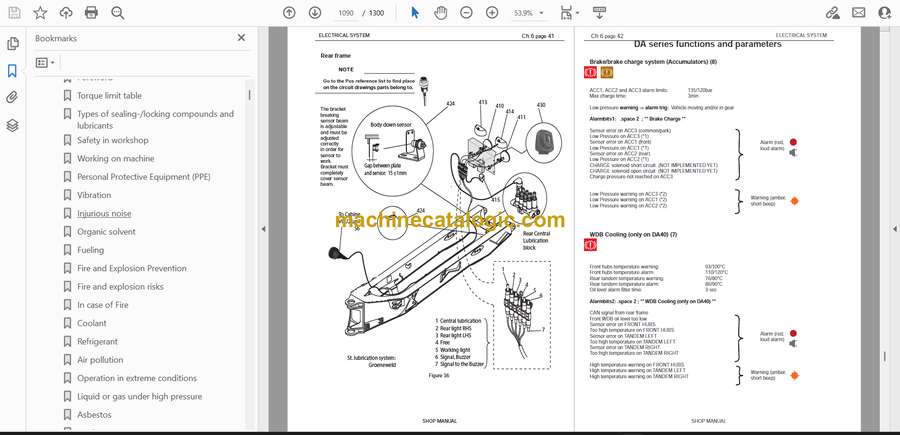
- Chapter 08 – Rear frame
- 8.1 Introduction
- 8.2.1 Dumper Body
- 8.2.2 Tilt Bearing
- DA30DA40 Final- 9 Option (VERKST-BOK – 1017585 – 1 – D) – 1
- 9 Optional Equipment
- 9.1 Automatic Tail Gate
- 9.2 Body heating system
- 9.2.1 View of the Exhaust Body Heating System
- 9.2.2 Assembly of The Exhaust Body Heating System
- 9.4 View of the Engine heater
- 9.4.1 Engine heater assembly
- 9.6 Webasto
- 9.6.1 Webasto
- 9.6.2 Assembly Preparation
- 9.6.3 Final assembly
- 9.7 Telematic system installation
- 9.7.1 Safety
- 9.7.2 Overview
- 9.7.3 Installation procedure
- 9.7.4 Checking functionality
- 9.7.5 TMS software update
- Chapter 10 – Error codes list
- English
- Engine
- Lubrication
- Display internal
- VCU2
- Transmission
- Silnik
- Układ smarowania
- Wyświetlacz główny
- VCU2
- Skrzynia biegów
- Motor
- Lubricación
- Pantalla interna
- VCU2
- Transmisión
- Moteur
- Lubrification
- Afficher interne
- VCU2
- Transmission
- Motor
- Zentralschmierung
- Bildschirm
- VCU2
- Getriebe
- SM Back cover DA30-5
- DA30DA40 Final- 1 Engine PDE (VERKST-BOK – 1030216 – 1 – G) – 1.pdf
- Engine identification
- Removal of engine assembly
- Lifting the engine
- Starting the engine
- Important information about the fuel
- Fuel system Tier2 (PDE)
- Schematic diagram of the fuel system Tier2
- Overflow valve
- General
- FUEL
- Temperature Dependency of the Fuel
- Fuel filter
- Changing the fuel filter
- Water separating prefilter PDE
- Changing the water separating fuel filter
- Bleeding the fuel system
- Feed pump
- Renewing the control unit
- Removing the ECU wiring Tier2
- Cylinder head – PDE System Tier2
- Cylinder head, parts view. PDE Tier2
- Special tools
- Valve mechanism
- Dismantling
- Renewing the valve stem seal
- Replacement of valve seats
- Machining the valve seats insert
- Renewing the valve guides
- Renewing PDE unit injector sleeves
- Assembly
- Fitting
- Unit injector fitting and flywheel access
- Valve and unit injector adjustment with PDE
- Order of adjustment for valve clearance and PDE unit injectors
- Flywheel readings (DA40)
- Flywheel readings (DA30)
- Adjusting the valve clearance and unit injectors
- Turbocharger
- Measuring radial clearance and axial clearance
- Renewing the turbocharger
- General
- Changing oil filter
- Oil analysis
- Checking oil level
- Changing the oil
- Special tools
- Pistons and cylinder liners
- Special tools
- Connecting rods
- Removing and dismantling connecting rods and pistons
- Renewal of bearing bushing in connecting rod
- Pistons
- Assembling piston and connecting rod
- Cylinderblock
- Cylinder liner
- Removing the cylinder liners
- Measuring the cylinder liner height
- Measuring the cylinder wear ridge and cylinder bore
- Fitting the cylinder liners
- Fitting the piston and connecting rod
- Flywheel and flywheel housing
- Special tools
- Removing the flywheel
- Renewing the rear crankshaft seal
- Removing the flywheel housing
- Fitting flywheel housing
- Fitting the flywheel
- Flexible coupling
- Safety instructions
- Functional description
- Disassembly and dismantling the coupling
- Assembling the coupling →7×1126;→8×1128.
- Installation instructions
- Friction disk, Friction ring
- Timing gear – 13 and 9 liter
- Gear drive
- Belt drive collant pump, generator and AC compressor
- Checking the Drive Belt
- Check for leaks
- Renewing the seal in the front cover
- Crankshaft damper
- Timing gear, view exploded
- Special tools
- Intermediate gear
- Camshaft gear
- Crankshaft gear
- Camshaft
- Replacement of camshaft bearing
- Crankshaft
- Removal
- Fitting
- Adjust – Machining the crankshaft
- Lubrication system
- General
- Oil pump
- Lubrication oilways
- Oil pressure
- Oil cooler, engine
- Oil cooler view See 010009
- Renewing seals and leakage testing
- Oil filter
- Centrifugal oil cleaner
- Dismantling and assembly
- Oil mist separator
- General
- High levels of oil carryover
- Crankcase pressure measurement
- Oil mist separator exploded view
- Oil mist separator disassemble
- Check – Rotational speed on oil mist separator
- Alternator 100 A
- Check
- Output test
- Renewal – Bearing and carbon brushes
- Oil pump, brake cooling circulate (DA40)
- Exploded view
- Disassemble and overhaul the oil pump
- Checking and renewing parts
- Oil circulate pump assemble.
- Renewing the gasket
- Cooling fan
- View of the radiator system DA40
- Cooling system
- Principal view of the cooling system
- Circulation
- Coolant
- Checking Coolant Level
- Pressure testing the cooling system
- Delivery valve
- External leakage
- Internal leakage
- Checking the Antifreeze Level
- Changing Coolant
- Filling Coolant
- Cleaning the Cooling System
- Removing oil cooler
- Disassemble the cooling unit
- Thermostat and thermostat housing
- Thermostat
- Coolant pump
- External cleaning
- Internal cleaning
- Technical data DC13 with PDE
- General data
- Technical data DC9 with PDE
- General data
- Troubleshooting ECOM / Canbus
- To do:
- Troubleshooting, -basic info.
- Diagnostic procedure
- Use of diagnostic kit
- Connection point Canpc + Testman
- Can bus overview
- SDP3 Scania dagnostic
- Retrieving data from VCU
- Troubleshooting Manual
- White smoke
- White smoke, water vapour
- White smoke, water vapour
- Black smoke on starting
- Blue smoke
- Fuel in the oil
- Oil in coolant
- Coolant/water in oil
- Low oil pressure
- High oil pressure (engine warmed up)
- Abnormal wear (liner, piston rings, etc.)
- Vibration, no driven components engaged
- Vibration when the clutch or reverse gear is engaged
- Vibration when alternator is in operation
- Engine speed hunting – single-speed engines with RQ governor
- Engine speed hunting – single-speed engines with RSV governor
- Delivery pipe fractures
- External corrosion on cylinder liner
- Engine difficult to start
- Fluid stroke
- Knocking/noise
- High oil consumption
- High fuel consumption
- Low compression
- Low engine output
- Hot engine
- Cold engine
- Coolant loss
- Polluted coolant
- Polluted coolant
- High oil temperature
- High exhaust temperature
- Low charge air pressure
- Low fuel pressure
- Low system voltage
- High system voltage
- External oil leakage
- External fuel leakage
- External coolant leakage
- Oil pressed out via crankcase ventilation
- Turbocharger breakdown
- Compressed air system
- Kopi av DA30DA40 Final- 2 Transmission (VERKST-BOK – 1017576 – 1 – E) – 1.pdf
- General
- Structure of the Repair Manual
- Denomination of standard dimensions
- Conversion table
- Torque limits for screws.
- Table
- Labeling of type plate
- Information on spare parts ordering
- Configuration of transmission
- Transmission schematics and gear schematics
- Gear schematics
- Measuring points and connections
- Table
- Measuring points for pressure oil and temperature
- Installation sheet
- Specjal tools for disassembly and reassembly
- Commercial tools for disassembly and reassembly
- Removal of transmission, disassembly
- Disassemble the structure bar
- Disassemble the hydraulic hoses
- Positioning for disassembly and reassembly
- Removal and refitting various components
- Transmission
- LKV axle insert
- Separate axle insert LKV from transmission
- Removal of speed sensor n4-output
- Disassembly of shifting block I and speed sensors
- Engine connection
- Oil supply
- Removal of shifting block II, valve block primary
- pump and retarder
- Retarder
- Valve block
- Shifting block II
- Primary pump
- Output to front and rear axle
- Output to front axle with axle insert LKV
- Output to front axle without axle insert LKV
- Output to rear axle
- Power take-off
- Version with 1st PTO
- Emergency steering pump
- Planetary drive “F”
- Separate planetary drive from housing II
- Removal input shaft and clutches
- Separate housing I and housing II
- Housing I
- Differential “G”
- Clutches “V”; “R”; “A”; “B”; “C”; “D”; “E”
- Housing II
- Clutches „V“; „R“; „A“; „B“; „C“; „D“; „E“ and Differential
- Clutch “E”
- Clutch “R”
- Idler
- Gear
- Clutch
- Clutch “B“
- Idler/Gear
- Gear
- Clutch
- Clutch “V“
- Clutch “C“
- Idler
- Gear
- Clutch
- Clutch “D“
- Idler
- Gear
- Clutch
- Clutch “A“
- Idler
- Gear
- Clutch
- Differential ”G“-”DA40 F“
- Differential without axle insert LKV ”G“
- Differential ”G“-”DA30 F“
- Differential with axle insert LKV ”G“
- Reassembly
- Clutches „V“; „R“; „A“; „B“; „C“; „D“; „E“ and Differential
- Clutch ”E“
- Clutch “R“
- Clutch “B“
- Clutch “V“
- Clutch “C“
- Clutch “D“
- Clutch “A“
- Differential ”G“-”DA40 F“
- Differential without axle insert LKV ”G“
- Differential ”G“-”DA30 F“
- Differential with axle insert LKV ”G“
- Installation input shaft and clutches
- Housing II
- Clutches “V”;“R”;“A”;“B”;“C”;“D”;“E”
- Housing I
- Assemble housing I and housing II
- Oil supply
- Shifting block II
- Valve block
- Retarder
- Primary pump
- Installation retarder, primary pump, valve block and shifting block II
- Engine connection
- Planetary drive “F”
- Planetary drive
- Mount planetary drive to housing II
- Output to front and rear axle
- Output to front axle with axle insert LKV ”DA30 F“
- Output to rear axle
- Power take-off
- Version with 1st Power take-off (PTO)
- PTO-gear – 1st power take-off
- PTO-input shaft
- Emergency steering pump
- Version with emergency steering pump
- Reassembly of shifting block I and speed sensors:
- Shifting block I
- Refitting of speed sensor n4-output
- Refitting breather, Oil sight level glass, Cover plate and screw plug
- Version with connection 1st PTO
- Refitting of LKV axle insert
- Disassembly of LKV Axle Insert ”DA30 F“
- Disassembly
- Reassembly of LKV Axle Insert ”DA30 F“
- Resassembly
- Determination of shim for contact pattern
- Reassembly of pinion
- Reassembly of differential
- Setting of backlash/crown wheel set and bearing rolling torque/differential
- Contact pattern check (Fig. 848 and 849)
- Preassembly and reinstallation of flange shaft
- Contact pattern examples of Gleason Tooth System
- Field of application:
- Ideal contact pattern:
- Contact pattern setting:
- Flank glossary:
- EXAMPLE 1: DEDENDUM TOOTH POSITION
- EXAMPLE 2: ADDENDUM TOOTH POSITION
- EXAMPLE 3: “LINE” CONTACT PATTERN
- Transmission assembly
- Clutch calibration
- Kopi av DA30 Final- 3 Drive line (VERKST-BOK – 1017577 – 1 – D) – 1.pdf
- Introduction
- General
- Structure of the Repair Manual
- Denomination of standard dimensions
- Conversion table
- Tightening torques for nuts and bolts.
- Table
- Drive line components
- Front reduction gear
- Parts list
- Front reduction gear cross section
- NAF special Tools for
- Assembly
- Drive shafts
- Front frame
- Rear frame
- Mounting the bearings on the intermediate shaft (B)
- Front differential and transmission
- Brakes
- Service brakes
- Service brake description
- Testing of parking brake
- Remove the Linings (→7×1145)
- Remove the Linings (7×1146→)
- Disassembly the park brake unit (→7X1145)
- Assembly the park brake unit.
- Disassembly the park brake unit from dump truck (7X1146→)
- Disassembly the park brake unit.
- Assembly the park brake unit
- Assembly the park brake
- Adjust the Initial Caliper Clearance (→7X1145)
- Adjust the Initial Caliper Clearance (7×1146→)
- Park brake Maintenance (→7X1145)
- Disc
- Troubleshooting Park brake
- Rear differential MOX-08
- Rear Differential
- Exchange of the complete rear differential
- Safety precautions.
- Repairs on the rear differential
- Exchange of crown gear / Pinion (7×1001-7×10²⁰)
- Exchange of crown gear / Pinion (7×10²¹ – up)
- Determining thickness of the adjusting washer (44)
- Determining thickness of the adjusting washer (45)
- Pinion bearing adjustment
- Backlash and crown gear bearing adjustment
- Checking contact pattern
- Exchange shaft seals
- Exchange of differential cage (compensating gearbox)
- Differential lock
- Planetary drive
- Complete exchange of planetary cage
- Exchange of sun gear shaft
- Testing and Adjusting of Thrust Stud Adjustment
- Exchange of Planetary Studs and Gears
- Exchange of ring gear carrier
- Wheel bearings
- Gear bearing exchange
- Gear bearing adjustment
- Brake
- Check disc’s wear
- Exchange of the piston seals for the operating brake
- Exchange of brake disks and pressure springs for the operating brake
- Tandem bearings
- Exchange of slewing ring
- Exchange of seal
- Exchange of axle beam
- Gear drive in tandem housing
- Exchange of bearing (84)
- Exchange of gear (43) and bearing (89) / (90)
- Exchange of gears (86)
- Checking clearance in the Tandem bearing.
- View of the Tandem bearing
- Special Tools for Mox 08 axle (7×1001 – 7×10²⁰)
- Rear differential MOX-17
- Disassembly
- Differential overview
- General information
- Recommendations for repairs
- Maintenance
- General information
- Differential + axle housing
- Bogie housing
- Wheel end
- Oil change
- Checking wear on multiple disk brake
- Remove the complete differential
- Disassembly
- Assembly
- Remove individual parts
- Disassembly
- Determine thickness of adjusting washer (23)
- Install pinion shaft
- Prepare differential housing (8) for the cardan flange sealing.
- Mounting multi disk differential lock (MDDL)
- Mounting differential cage
- Check contact pattern
- Tightening torques pattern
- Differential cage
- General Information
- Exchange gears
- Multi disk differential lock (MDDL)
- Parts overview
- Disassembly
- Assembly
- Tightening torque
- Axle housing
- Axle housing overview
- Disassembly
- Disassembling the sliding ring
- Disassembling the drive shaft
- Disassembling the axle housing
- Assembly
- Mounting axle housing
- Assembly half shaft
- Determine the washer for axial gap
- Bogie housing
- Bogie housing overview
- General information
- Disassembly
- Disassembling the complete bogie housing
- Removing individual parts
- Assembly
- Assembling the complete bogie housing
- Mounting individual parts
- Wheel end
- Wheel end overview
- Planetary assembly overview
- Ring piston brake cylinder overview
- General information
- Disassembly
- Disassembling the complete wheel end
- Disassembling individual parts
- Assembly
- Assembling the complete wheel end
- Mounting individual parts
- Special Tools for Mox 17 axle (7×10²¹ – up)
- Special Tools
- General information
Develon


